www.mech-sci.net/3/25/2012/ doi:10.5194/ms-3-25-2012
©Author(s) 2012. CC Attribution 3.0 License.
Mechanical
Sciences
Open AccessUnderstanding the drivers for the development of design
rules for the synthesis of cylindrical flexures
M. J. Telleria and M. L. Culpepper
Massachusetts Institute of Technology, Cambridge, USA
Correspondence to: M. J. Telleria ([email protected])
Received: 28 February 2011 – Revised: 21 March 2012 – Accepted: 24 March 2012 – Published: 12 April 2012
Abstract. Cylindrical flexures (CFs), defined as flexures with only one finite radius of curvature loaded nor-mal to the plane of curvature, present an interesting research direction in compliant mechanisms. CFs are constructed out of a cylindrical stock which leads to geometry, manufacturability, and compatibility advan-tages. Synthesis rules must be developed to design these new systems effectively. Current knowledge in flexure design pertains to straight-beam flexures or curved flexures loaded along the plane of curvature. CFs present a challenge because their mechanics differ from those of straight beams, and although their modelling has been researched thoroughly it has yet to be distilled into element and system creation rules. This paper uses models and finite element analysis to demonstrate that current design rules for straight-beam flexures are insufficient and inadequate for the design of CF systems. The presented discussion will show that CFs differ both at the element and systems levels, and therefore future research will focus on developing the three com-ponents of the building block approach: (i) reworking of element mechanics models to reveal the parameters which cause the kinematics of the curved beam to differ from those of the straight beam, (ii) development of a visual stiffness representation, and (iii) formation of system creation rules.
1 Introduction
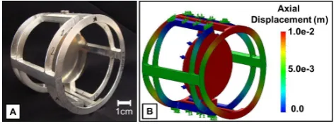
Cylindrical Flexures, CFs, are defined as flexure systems with elements that have only one finite radius of curvature and are loaded normal to their plane of curvature. In other words, systems composed of flexure beams that are curved in a single plane. Figure 1 shows a prototype of a particu-lar CF system. The system shown in Fig. 1 is actuated by loading the flexures normal to their plane of curvature. This specific loading condition is presented because it offers the most challenging research aspects and it is the least studied.
Past research has given different names to flexures that fall under this definition. The most applicable definition is Smith’s “hinges of rotational symmetry”, which he defines as flexures constructed from solids of revolution (Smith, 2000). The flexure shown in Fig. 1 fits within Smith’s definition be-cause of its axial symmetry. This definition is expanded to allow CFs to be fractions of a cylinder. The work is scoped by constraining CFs to elements with a single finite radius. Finally the system must have well defined distortions for it
to be classified as a CF. The focus of this paper is to demon-strate: (i) the usefulness of design rules in the design pro-cess, (ii) that current design rules for straight-beam flexures are insufficient and inadequate for the design of systems with curved-beam flexures, (iii) the need for future research at the element and systems level, to develop guidelines for the de-sign of CF systems.
1.1 Prior art
26 M. J. Telleria and M. L. Culpepper: Drivers for design rules for cylindrical flexures
Figure 1. The quad compound-spring cylindrical flexure, CF, ex-ample: (A) 7075Al prototype and (B) FEA model depicting its ac-tuation.
synthesis is the work by Kim et al. (2008), which uses curved beam building blocks (CBB) to create flexure systems. This paper differentiates itself from CBB in that in this case the beams are loaded normal as opposed to parallel to the plane of curvature. This loading condition requires the analysis of the flexures in three dimensions.
The other area of prior art pertains to the analysis of spe-cific systems that fit within the CF definition. Smith (2000) presents detailed analysis on the disc coupling and the ro-tationally symmetric hinge. These types of analyses have produced useful flexure systems; however there has been lit-tle overarching insight developed that could be used to cre-ate new CF concepts. In many cases the analysis of these systems has relied on FEA given the lack of knowledge on what parameters determine the system performance. The biggest knowledge gap comes in the form of understanding how to assemble these curved elements to create predictable systems.
The lack of design guidelines restricts the design process. The rapid generation of concepts is limited, since the de-signer does not have a simple way to predict the general be-havior of a system composed of CF elements. In addition optimization is tedious because there is little understanding of the effect of different parameters.
1.2 Advantages of CFs
Cylindrical flexures present geometry, manufacturability, and compatibility advantages over traditional flexure sys-tems. Their axial symmetry may be used to achieve insen-sitivity to thermal changes, and to decrease the effects of manufacturing and load placement errors. Monolithic sys-tems with a variety of flexure elements can be created out of a single piece of round stock reducing assembly cost and errors.
CF fabrication is facilitated by the availability of accurate round stock. CFs can be manufactured at low cost by using traditional machining methods. The prototype in Fig. 1 was machined using a 4-axis Mazak brand lathe. Other manu-facturing methods include: a waterjet with a rotary axis and a 5-axis mill. CF’s most attractive quality is their compat-ibility with rotating applications, laparoscopic tools, optical
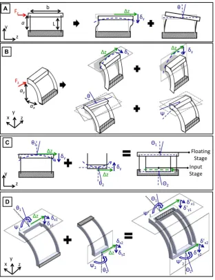
Figure 2. (A) Straight-beam mechanics, F is the load on the beam, Mris the resulting bending moment,∆z is the displacement along the z-axis, andθis the parasitic rotation about the x-axis. (B) Curved-beam mechanics, highlighting the added twist, ψ, and torque, Trand (C) Curved-beam parameters. R represents the radius of curvature,φis the sweep angle, tris the thickness of the beam in the radial direction, and tais the thickness in the axial direction.
systems, and other applications benefiting from their cylin-drical geometry.
2 Knowledge gap: need for CF research
This section focuses on explaining how and why CFs be-have differently than straight-beam flexures. These diff er-ences make current design guidelines inadequate for the ef-fective creation of CF concepts. The variations from straight-beam behavior are illustrated by looking at a curved can-tilever beam loaded at its free end. In this case the desired motion is a displacement along the z-axis. All other displace-ments are defined as parasitic motions.
2.1 Mechanics
Curved flexures have additional complexities over straight beams both at the element and system levels. The curvature of the beam leads to an added rotation and resulting torque. Figure 2 shows that for a given load, F, the flexure will twist,
ψ, which leads to a resulting torque, Tr, at the base. Sect. 3.1
presents the proposed process for developing element design rules from current curved-beam models.
The curvature of the beam also leads to challenges in the conceptual assembly of curved-beam flexure systems. The traditional rules for adding elements have to be augmented to include the effects of the added twist and torque. The four-bar linkage and Jones et al.’s (1956) compound rectilinear spring are used to demonstrate the need for additional system creation rules.
Figure 3. (A) Straight four-bar linkage parameters, a indicates the location of Fz relative to ground. Figure shows the three motions
associated with Fz applied onto the platform. Desired displacement∆z is indicated with green, while the parasitic motions,θandδy,are
shown in blue. (B) Curved four-bar linkage parameters and displacements under Fz; ayand axindicate the location of the force relative to
ground. The curvature results in twoδparasitic motions,δxandδy, and an additional rotation of the stage,Ψ. (C) Straight compound-spring.
Nesting of the two four-bars results in cancellation of theδparasitic motions. Θ1andΘ2indicate the rotations of the stages in the nested system. (D) Curved compound-spring. Cancellation of theδmotions is not straight forward.
vertical motion,δy, presented in Eqs. (1) and (2). In these
equations L represents the length of the flexure beam, b is the distance separating the flexures, a is the distance from the load input location to ground, t is the thickness of the beams, and∆z is the desired displacement along the load direction.
The parameters are defined in Fig. 3a. The vertical motion of the stage,δy, in conjunction with the desired displacement,
∆z, will result in the stage following an arc as Fzis applied,
as highlighted in Fig. 3a.
θpitch=
6(L−2a)·t2
3b2L−2t2+6at2 ! ∆z
L
!
, (1)
δy≈
(∆z)2
2L . (2)
Equations (1) and (2) are used by designers to estimate the parasitic motions of a straight four-bar system. These equa-tions have been derived for straight-beam flexures and must be expanded in order to describe a four-bar composed of curved beams. Figure 3b shows that for an input load nor-mal to the plane of curvature, Fz, the motion of the input
28 M. J. Telleria and M. L. Culpepper: Drivers for design rules for cylindrical flexures
curvature of the flexures, the CF four-bar the stage will travel in two arcs dictated by∆z,δyandδx, and it will experience
two rotations about its centerθ,Ψ. Future research is nec-essary in order to develop a set of equations that accurately predict the parasitic motions of the four-bar CF system.
The design of precision machines requires that the para-sitic motions are well understood and minimized to achieve the desired displacement. Studies have shown that for a four-bar linkage load placement and nesting of systems can be used to reduce the parasitic motions. As Eq. (1) showsθpitch
can be reduced by moving the location of the input load, a. The challenge in the curved version of the four-bar linkage is that the load location is now defined by two coordinates
ax and ay, as shown in Fig. 3b. Once again the currently
available knowledge is insufficient to design a curved-beam flexure system.
Nesting of two four-bar flexure systems, referred to as the compound rectilinear spring, has been used to mitigate the parasitic arcing motion caused by δy as shown in Fig. 3c.
In the compound-spring theδy motion of the input stage is
matched by an equal and opposite δy of the floating stage
resulting in a cancellation of the arcing motion of the input stage. Theδymotions are mitigated as long as both four-bars
are constructed of identical flexure beams, therefore achiev-ing the same∆z displacement and as a result the same
mag-nitude ofδy. It is important to note that the nesting of the
flexures does not remove the parasitic rotations of the stages,
θ1andθ2, but these rotations are affected by the nesting and
are labelledΘ1 andΘ2 in Fig. 3c to reflect this. Figure 3d
shows what happens when a compound-spring is created us-ing two curved four-bars. Due to the curvature, the floatus-ing and input stages are located on different planes. As a result the cancellation of theδmotions is not straight forward and requires further research; the resultingδmotions will depend on the magnitude ofδyandδxas well as the sweep angle,
φ. Section 3.3 discusses the proposed research approach for creating system rules that will allow the designer to manage the parasitic motions of CF systems.
2.2 Stress
In order to determine the range of a system, both the displace-ment to a given load and the resulting stress must be consid-ered. The curvature of the element leads to a torque on the fixed end of the cantilever beam. This torque will affect the resulting stress calculation. Using energy conservation prin-ciples it can be identified that an added torque requires that there be a decrease in the original resulting moment. Both of these effects will change the magnitude and distribution of the stress along the beam.
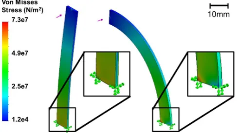
Figure 4 shows that a stress concentration is observed at the base on the inner radius of the curved element. Future work will develop guidelines that will allow the designer to account for the new stress distribution and perhaps find a way to distribute the stress more evenly. Previous work has shown
Figure 4.Finite element analysis of two cantilevered beams of the same properties under the same loading force. The stress concen-tration on the curved beam is highlighted.
contouring of the thickness of the flexure to be a successful way to distribute stress along the length of a beam (Timo-shenko, 1930).
3 Research approach and impact
The main three compliant mechanism synthesis approaches are topology synthesis, pseudo-rigid modelling, and build-ing block approach. A buildbuild-ing block approach derived from constraint-based design is proposed as the most appropriate synthesis methodology for CFs at this time (Maxwell, 1890; Blanding, 1999; Hale, 1999). The plan is to first develop a full understanding of the parameters that affect the element’s behavior. This element then becomes the building block for CF systems. The next step is to develop rules for how these blocks interact when added together. The desired outcome of the research consists of (i) a visual representation that allows the designer to quickly understand how different parameters will affect the behavior of an element, similar to a stiffness ellipsoid (Kim, 2008) and (ii) design guidelines for the gen-eration of CF systems.
Figure 5. The curvature adjustment factors,ζ, show how the be-havior of the curve beam deviates from that of a straight beam as a function of the geometry of the beam. Curvature adjustment factors are obtained from Roark’s closed-form solutions. ζz corresponds
to the z-axis displacement multiplier as shown in Eq. (7), whileζθ
andζΨcorrespond to the multipliers for the two parasitic motions
θandΨ, respectively. FinallyζMr andζTr represent the curvature
adjustment factors for the resulting moment and torque at the base of the beam. Flexure length is held constant by varying the radius of curvature. (A) Curvature adjustment factors,ζ, vs. sweep angle,
φ. The graph shows that as the sweep angle goes to zero the curved beam behaves as a straight beam,ζz,ζθ,ζMr go to 1, andζΨandζTr
approach zero. While as the sweep angle increases the behavior of the curved beam deviates from that of the straight beam. (B) Cur-vature adjustment factors,ζ, vs.β,βis the ratio of elastic to shear properties of a curved beam as defined by Eq. (4).
3.1 Element mechanics
The first step in the building block approach is to understand the flexure element mechanics. The goal is to identify what parameters affect the element’s performance. Roark’s equa-tions for curved beams loaded normal to their plane of cur-vature are used to understand the kinematics of the curved beam and to find the parameters that play an additional role in the motion of the curved beam (Young and Budynas, 2002). Cantilever beams loaded at their free end are first examined. Future work will explore the effect of load location.
Figure 2c shows the different parameters that define the curved flexure element. Roark presents equations for the dis-placements resulting from a load, F, at the free end of the
beam (Young and Budynas, 2002). The z-displacement,∆z,
is the desired motion. This displacement is given by Eq. (3), where R is the radius of the beam, E is the elastic modulus, I, is the second moment of area, andφis the sweep angle. Ca6, Ca9, Ca3 are functions ofφandβ, defined in Roark (Young
and Budynas, 2002). Equation (4) definesβas the ratio of elastic to shear properties of the beam, where G is the shear modulus, and k is a torsional stiffness constant. More details on these equations can be found in Roark (Young and Bu-dynas, 2002). Equations (5) and (6) from Roark are used to calculate the two parasitic motion of the cantilever beam,θ andΨwhich are defined in Fig. 2b.
∆z=FR
3
EI ·(Ca6sin(ϕ)−Ca9(1−cos(ϕ))−Ca3), (3)
β=E·I
G·k. (4)
θ=F·R2
E·I (Ca6cos(ϕ)−Ca9sin(ϕ)) (5)
Ψ =F·R2
E·I (Ca9cos(ϕ)+Ca6sin(ϕ)) (6)
It is proposed that a more efficient way to look at Eq. (3) is to factor it into the straight-beam equation and a curvature adjustment factor, ζz, as shown in Eq. (7). In Eq. (7) the
length, L, is the product of R, andφ. Equation (8) shows that the curvature adjustment factor is calculated by dividing the displacement given by Roark in Eq. (3) by the straight-beam displacement equation. The curvature adjustment factors for the parasitic motions,ζθandζΨ, are similarly calculated.
∆z=ζz FL3
3EI, L=R·ϕ (7)
ζz=3·(Ca6sin(ϕ)−Ca9(1−cos(ϕ))−Ca3)
.
ϕ3 (8)
This new representation allows the designer to use all previ-ous knowledge of straight-beam behavior and then evaluate what parameters play an additional role in the behavior of the curved beam. The added role of parameters is evaluated by identifying their effect onζz. Ifζzdoes not depend on the
parameter then that parameter does not have an additional ef-fect, relative to its effect on a straight beam’s mechanics. If
ζz is a function of that parameter then the parameter plays
an additional role. Analysing the parameters in Eq. (1) it is found thatζz,ζθ, andζΨdepend only onφandβ.
The next step is to understand how these two parameters affect the mechanics of the beam. Figure 5a shows how as
φapproaches zero the curved beam behaves like a straight beam. Then asφincreases the behavior deviates. Figure 5b shows the curvature adjustment factor for each of the mo-tions ζz, ζθ andζΨ, vs. β. The value of β for a given
30 M. J. Telleria and M. L. Culpepper: Drivers for design rules for cylindrical flexures
Figure 6.∆z-stiffness vs. sweep angle,φ, for three constraint con-ditions. K1 corresponds to a cantilever beam, K2 represents a fixed slope constrained beam, and K3 corresponds to a fixed end-slope and twist constrained beam. Flexure length is held constant by varying the radius of curvature.
research will analyse how the sweep angle,φ, andβaffect common flexure performance metrics.
3.2 Stiffness representation
Once the mechanics are understood, a stiffness representa-tion can be developed. This representarepresenta-tion will allow the designer to quickly identify how the elements will behave. This can be done using either stiffness or compliance ellip-soids (Kim et al., 2008). A stiffness ellipsoid visually shows the relative magnitude of the stiffnesses of a beam. The∆
z-stiffness of the beam depends on the loading conditions and element constraints. The previous analysis focused on can-tilevered beams; however, flexures are usually constrained in systems. Therefore, the effect of different constraint con-ditions on the∆z-stiffness is explored. The change in ∆
z-stiffness withφis evaluated, because sweep angle is the dom-inant parameter.
Figure 6 shows the ∆z-stiffness vs. φ for three different constraint conditions: (i) cantilever beam, K1, (ii) slope con-strained, K2, and (iii) slope and twist concon-strained, K3. The length of the flexures is held constant in this analysis by vary-ing the radius of curvature. The graph for K1 corresponds to the cantilever beam analysed in Fig. 5. From the mechan-ics analysis K1 is expected to increase withφ, given∆z
de-creases withφ. K2 decreases withφ because both ∆z and
θ decrease with φ. This decrease in slope translates to a smaller moment being applied at the free end to achieve the zero slope condition. Finally K3 increases withφ. This same analysis will be carried out for all stiffnesses leading to the creation of the stiffness ellipsoids.
The presented equations of motion for the curved can-tilever beam analysed in Figs. 5 and 6 are corroborated us-ing FEA models. Figure 7 plots the predicted displacements
Figure 7.Comparison of the FEA and closed-form equation calcu-lations of the curved beam displacements vs. sweep angle,φ, for a cantilever beam, K1. Max error between models is 7 %.∆z repre-sents the desired motion along the z-axis of the beam as indicated in Fig. 2b.θandΨcorrespond to the two parasitic rotations of the beam under a load normal to the plane of curvature. Flexure length is held constant by varying the radius of curvature.
Figure 8. FEA of a curved compound-spring under a 10 N load (A) No deformation of input stage (B) Deformed input stage as a result of the four-bar twist stiffness, Kψ, being larger than the stage
stiffness.
from both models. The next step will be to compare these models to experimental results. Future research will expand on the kinematic analysis by assembling the 6×6 stiffness matrix for a curved beam.
3.3 System analysis
Figure 9.(A) Double curved spring. (B) Stage driven by two separate double curved springs, the quad compound-spring CF design.
Table 1.Main stage tip and tilt angle in microradians per millimeter of z-axis displacement for the different compound-spring iterations (flexure length is constant for all iterations).
Tilt angleθ Tip angleΨ µrad mm−1 µrad mm−1
Flat straight compound 58.5 0.00 90◦
curved compound 321 101
Double curved compound 0.00 211 Two double curved compound 0.00 5.04
Element spacing plays a critical role in system creation. It is well-established that parasitic rotations of a shaft de-crease with the distance between the bearings, b, squared. Equation (1) shows that the pitching motion of a four-bar de-creases with b2 and Eq. (9) presents that the twist stiffness,
Kψ, of a straight four-bar increases with b2(Smith, 2000).
Kψ= EI
b2L, (9)
For straight-beam systems both parasitic motions decrease with b2. Using only this information may lead the designer
to maximize the spacing between the flexure beams. This is not only a problem in terms of weight and volume. It is also found that since the parasitic motions have not been miti-gated, when the four-bar’s spacing is large enough, Kψ is
greater than the stiffness of the stages and the stages begin to deform, as shown in Fig. 8. Increasing the spacing be-tween the beams is not a complete solution for reducing the parasitic motions.
Load location has been shown to play a critical role in reducing the parasitic motions of a system (Slocum, 1992; Hopkins, 2010). Therefore, future research must establish rules and equations that describe the effect of the load lo-cation on the parasitic motions of a curved system. The
re-search approach proposed is to first establish the optimal load location for a curved-beam element and how this position changes with sweep angle. Then to determine how to use center of stiffness rules to find the best actuation point of a CF system.
Section 2.1 showed that a curved four-bar system has four parasitic motions and postulated that in a curved compound-spring theδmotions of the stage are not mitigated through the nesting because they occur on two different planes and have differentδxandδymagnitudes. The question then
be-comes how do to deal with the additional parasitic motions and the fact that they are occurring on two different planes. The following example is used as a way to demonstrate some of the challenges of CF system creation. The goal of the pre-sented system is to translate a stage along the CF’s central-axis with minimal tip and tilt error. To do this the parasitic
θandΨmotions of the flexure system have to be minimized and the∆z displacement maximized. Precision engineering
applications require high accuracy flexure systems; microns of parasitic motion can cause a design to fail.
32 M. J. Telleria and M. L. Culpepper: Drivers for design rules for cylindrical flexures
4 Conclusions and future work
This paper uses analysis of common flexure mechanisms to demonstrate that current design rules for straight-beam flex-ures are insufficient for designing effective CFs. The insights that this research has already generated guided the correc-tion of a CF design achieving a 20×reduction in parasitic errors. The result is a new CF concept that is compatible with cylindrical geometries. Continuing research in this area will develop a full set of design insights and a stiffness rep-resentation that will enable a designer to create CF systems effectively.
Acknowledgements. This work was supported in part by the National Science Foundation Graduate Fellowship Program and Lincoln Laboratories. Special thanks to MIT’s BioInstrumentation lab for the use of their Mazak Lathe.
Edited by: J. Herder
Reviewed by: B. Trease and D. Brouwer
References
Blanding, D. L.: Exact Constraint: Machine Design Using Kine-matic Principles, ASME Press, New York, 1999.
Hale, L. C.: Principles and Techniques for Designing Precision Machines, Ph.D. thesis, Massachusetts Institute of Technology, USA, 1999.
Hopkins, J. B.: Design of Flexure-Based Motion Stages for Mecha-tronic Systems via Freedom, Actuation and Constraint Topolo-gies (FACT), Ph.D. thesis, Massachusetts Institute of Technol-ogy, 2010.
Jones, R. V., Phil, D., and Young, I. R.: Some parasitic deflexions in parallel spring movements, Scientific Instruments, 33, 11–15, 1956.
Kim, C. J., Moon, Y., and Kota, S.: A building block approach to the conceptual synthesis of compliant mechanisms utilizing compliance and stiffness ellipsoids, Mech. Design, 022308-1– 002308-11, 130, 2008.
Lee, H.: Generalized Stiffness Matrix of a Curved-Beam Element, AIAA Journal Technical Notes, 7, 2043–2045, 1969.
Maxwell, J. C.: General considerations concerning scientific appa-ratus, The scientific papers of James Clerk Maxwell, edited by: Niven, W. D., Dover Press, (Reprinted from the handbook to the special loan collection of scientific apparatus, 1876), 1890. Slocum, A. H.: Precision machine design, Society of
Manufac-turing Engineers, Society of ManufacManufac-turing Engineers, Prentice-Hall, Inc., USA, 1992.
Smith, S. T.: Flexures: Elements of elastic mechanisms, CRC Press, USA, 2000.
Timoshenko, S.: Strength of materials, D. Van Nostrand, USA, 1930.