ISSN (e): 2250-3021, ISSN (p): 2278-8719
Vol. 08, Issue 5 (May. 2018), ||V (IV) || PP 43-49
Development of a Motorized Soybean Dehulling Machine for
Small Scale Farmers
Akintola, A.
1*, Ogunsola, F. O.,
2Adesola, A. A.
1and Ogunremi, M.
1 1Department of Agricultural and Bio-Environmental Engineering, Oyo State College ofAgriculture and Technology, Igboora.
2Department of Food Technology, Oyo State College of Agriculture and Technology,
Igboora.
*Corresponding Author: [email protected]
Abstract: Soybean has been recognized as so versatile that can be processed into a wide variety of food
products the soybean can be dried and wet processed. Soybean is also a valuable source of edible oil and excellent source of protein useful for both human and animal feeding. Protein is very important and is required for growth, repair of muscles and nutritional balance. The intake of soybean that is gaining acceptability both by the rural and urban dwellers calls for development of de-hulling machine to reduce the drudgery that involved in traditional method of de-hulling the beans. The de-hulling of soybean machine was based on abrasion between the beans and the wall of the de-hulling chamber and between the beans. The machine consists of the inlet hopper, the de-hulling chamber which included the barrel and the auger specially designed to create abrasion on the beans as it is carrying them towards the outlet end, 1HP geared motor with pulley and belt to make up the transmission unit. The overall dimensions of the machine are 460mm x 750mm x 250mm. The machine has de-hulling capacity of 40.00 to 54.55 Kg/hr and efficiency of 87% to 93% with the highest efficiency gotten when 2Kg of the samples were soaked for five hours before dehulling. The output result falls within economic range, therefore it is recommended for small soybeans processors.--- --- Date of Submission: 27-05-2018 Date of acceptance: 10-06-2018 --- ---
I.
INTRODUCTION
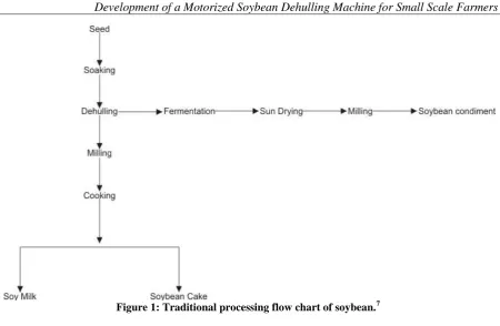
Figure 1: Traditional processing flow chart of soybean.7
II.
MATERIAL AND METHODS
Design Considerations
The factors considered for selection of materials for the fabrication included the cost of the machine, so as to enhance its use of materials, power sustainability, reliability, workability requirement and the efficiency labour requirement in operating the machine. Also, considered in the design was the ease of replacement of component parts in case of damage or failure and the durability of the materials, corrosion resistance, rigidity, strength and rust. The materials selected to suite the design considerations are shown in Table 1.
Table 1: Material selection for the fabrication of the machine S/N MACHINE
COMPONENTS
SUITABLE ENGINEERING MATERIAL
CRITERIA FOR MATERIAL
SELECTION
MATERIAL SELECTED
REMARKS
1. Hopper
a. Side plates, partition plates, front and rear cover
b. Frame
Galvanized sheet, stainless steel and aluminum sheet. Mild steel and square pipe angle iron.
Corrosion resistance, workability and cost. Strength, rigidity and lightness
Galvanized metal sheet
Angle Iron
Corrosion and cost effectiveness
Strength
2 Sharf Medium carbon steel Availability, cost and
strength
Medium carbon steel Availability and cost effectiveness 3 Pulley Cast iron, mild steel, wood
forged iron and aluminum
Strength, availability, and cost
Cast iron Strong and readily available
4 Belt Rubber and leather Strength and flexibility Rubber Flexibility and
strength
5 Bearing P205 Axial loading and radial
loading
Pillow bearing Accommodate e both axial and radial loading
Machine conception
The motorized soybean hulling machine developed, is sub-divided in four units namely; the hopper, de-hulling chamber, the outlet and the power unit.
Mode of operation of the machine
The motorized soybean de-hulling machine was developed using abrasion force. The machine consists of a two hopper (water inlet and seed inlet), two semi-concentric cylinders (one perforated to allow the hull to pass through it and the other not perforated) and a driving mechanism. De-hulling takes place in the annular space between rotating shaft and stationary cylinder.
Design Calculations
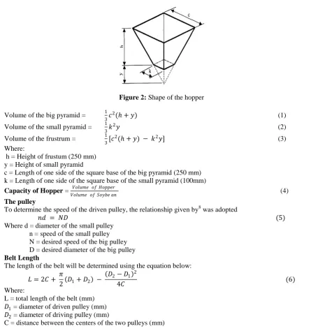
Figure 2: Shape of the hopper
Volume of the big pyramid = 1
3𝑐
2( + 𝑦) (1)
Volume of the small pyramid = 1
3𝑘
2𝑦 (2)
Volume of the frustrum = 1
3[𝑐
2( + 𝑦) − 𝑘2𝑦] (3)
Where:
h = Height of frustum (250 mm) y = Height of small pyramid
c = Length of one side of the square base of the big pyramid (250 mm) k = Length of one side of the square base of the small pyramid (100mm)
Capacity of Hopper = 𝑉𝑜𝑙𝑢𝑚𝑒 𝑜𝑓 𝐻𝑜𝑝𝑝𝑒𝑟
𝑉𝑜𝑙𝑢𝑚𝑒 𝑜𝑓 𝑆𝑜𝑦𝑏𝑒 𝑎𝑛 (4)
The pulley
To determine the speed of the driven pulley, the relationship given by8 was adopted
𝑛𝑑 = 𝑁𝐷 (5) Where d = diameter of the small pulley
n = speed of the small pulley N = desired speed of the big pulley D = desired diameter of the big pulley
Belt Length
The length of the belt will be determined using the equation below:
𝐿 = 2𝐶 + 𝜋
2 𝐷1+ 𝐷2 −
𝐷2− 𝐷1 2
4𝐶 (6) Where:
L = total length of the belt (mm) 𝐷1 = diameter of driven pulley (mm)
𝐷2 = diameter of driving pulley (mm)
C = distance between the centers of the two pulleys (mm)
The Belt Drive
Belts are used to transmit power in equipment. It requires close spacing and centre distance. It transmits power from motor to the shaft making the center distance between motor and shaft to be adjustable.
The twisting moment (T) was given as:
𝑇 = 𝑇1 – 𝑇2 𝑥 𝑅 (7)
Where:
T1 = Tension in the tight side
T2 = slack side of the belt
R = Radius of the pulley
Tension ratio for an open belt was calculated using equation (8)
Let 2.3𝑙𝑜𝑔 𝑇1
𝑇2 = µ𝜋 (8)
Where: µ is the coefficient of friction between rubber belt and mild steel pulley given by 0.3. The Shaft:
The shaft was made from mild steel with the following parameters: Yield strength of the material, Y = 320 N/mm2
Since the loading of soybeans seed is not strong, it was assumed that load was applied gradually, The combined shock and fatigue factor applied to bending moment, Km = 1.0
The combined shock and fatigue factor applied to torsional moment, Kt = 1.5 The motor rating is 750 W at 1440 rpm.
And if keyways are present, it will reduce to 23% and the shear stress of the shaft will be 84MPa = 84Nmm2. The co-efficient fraction between the belt and pulley is 0.3 and the angle of lap of the belt is 1800.The diameter of the pulley is 130mm.
𝑇 = 60 x P
2 𝑥 𝜋 𝑥 𝑁 (9)
Where:
T = Twisting moment
P = Power rating of the motor
N= Speed of the shaft
Critical speed of the shaft (ωs):
The critical speed of the shaft was determined by equation (10) given by 8
𝜔𝑠 = =
48𝐸𝐼
𝑀𝐿2 (10)
Where:
E is the Modulus of elasticity of steel
I is the moment of inertia given by 𝜋𝑑 4
64
L is the shaft length.
Dehulling chamber design
The dehulling chamber was assumed to be a thin walled cylinder, the targential stress perpendicular to the axis of the cylinder is given in equation (11) as:
𝜎 =pddc
2𝑡 (11) Where:
σ = perpendicular of hoop stress, assumed to be the maximum tensile stress the cylinder is subjected to at failure by yield.
P = Internal pressure
t = Thickness of dehulling chamber
ddc = internal diameter of dehulling chamber
Also, 𝜎 = 𝑆𝑎𝑙𝑙 = (0.5 𝑆𝑦)
𝑁 (12)
Where:
Sall = allowable shear stress
N = factor of safety Sy = Yield stress
Volume of dehulling chamber
This is given by
𝑉𝑑𝑐 = 𝜋 𝑟𝑑𝑐2𝑙𝑑𝑐 (13)
Where: rdc=radius of dehulling chamber
ldc = length of dehulling chamber
Machine Parts
The Hopper: it consists of two hoppers (one for water and the other is for the seed). This is where the soybean and the water are conveyed into the dehulling chamber. It is made of plate of thickness 2mm in a pyramid shape. The Dehulling Chamber: It contains the shaft coupled with auger which will dehull the soybean. The dehulling chamber consist of two half cylinders fabricated together. The first half cylinder is perforated with a 7mm drill bit to allow the chaff to move out through the side outlet.
The Outlet Unit: The machine has two outlets; one at rear side and the other located in the front of the machine. The side outlet will convey the chaff out of the machine and the front outlet will convey the dehulled soybean out of the machine.
Test procedure
The soybean dehulling machine was fabricated and tested in other to know the capacity and the efficiency of the machine. Three different quantities of soybean (1.5Kg, 2Kg and 2.5Kg) were soaked for 3 hours, 4 hours and 5 hours. After that, it was fed into the dehulling chamber of the machine. The efficiency and machine capacity was determined for each quantity of soybean and each soaking time as shown in equation (14) and (15) respectively given by 9.
𝑇𝑒 𝑒𝑓𝑓𝑖𝑐𝑖𝑒𝑛𝑐𝑦 =𝑇𝑜𝑡𝑎𝑙 𝑛𝑢𝑚𝑏𝑒𝑟 𝑜𝑓 𝑑𝑒𝑢𝑙𝑙𝑒𝑑 𝑠𝑒𝑒𝑑𝑠
𝑆𝑢𝑚 𝑡𝑜𝑡𝑎𝑙 𝑛𝑢𝑚𝑏𝑒𝑟 𝑜𝑓 𝑠𝑒𝑒𝑑𝑠 𝑥 100 % (14)
𝑇𝑒 𝑚𝑎𝑐𝑖𝑛𝑒 𝑐𝑎𝑝𝑎𝑐𝑖𝑡𝑦 𝐾𝑔
𝑟 =
𝑇𝑟𝑜𝑢𝑔𝑝𝑢𝑡
𝑇𝑖𝑚𝑒 𝑡𝑎𝑘𝑒𝑛 𝑡𝑜 𝑑𝑒𝑢𝑙𝑙 (15)
III.
RESULT
The soybean dehulling machine was fabricated and the materials of construction have been listed. Figure 3a and 3b shows the orthographic projection of the machine.
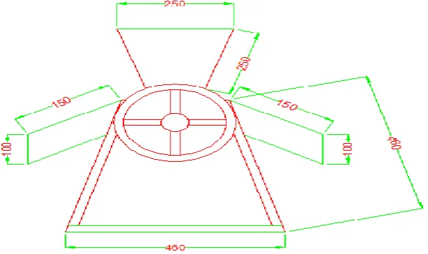
Figure 3a:Orthographic projection (side view) of the soybean dehulling machine. (All dimensions in mm).
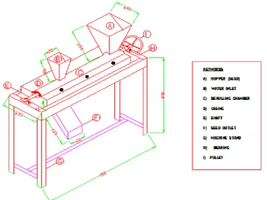
Figure 4: Isometric view of the soybean dehulling machine constructed. All dimension in mm.
IV. DISCUSSION
The soybean dehulling machine was tested and the result was shown in Table 2.
Table 2: Performance evaluation of the soybean dehuller showing efficiency and machine capacity.
Test Quantity of
soybean (Kg)
Soaking time (hr)
Dehulling time (s)
Percentage of dehulled soybean (%)
Machine capacity (Kg/hr)
1 1.5 3 135 87 40.00
1.5 4 128 90 42.19
1.5 5 120 92 45.00
2 2.0 3 161 89 44.72
2.0 4 152 91 47.37
2.0 5 140 93 51.43
3 2.5 3 188 89 47.87
2.5 4 174 90 51.72
2.5 5 165 92 54.55
From Table 2, the dehulling time decreases as the soaking time increases and increases as the quantity of soybean increases. The efficiency of the machine ranges from 87% to 93%, the highest efficiency was gotten when 2Kg of soybeans was soaked for five hours before dehulling. The machine capacity also increased as soaking time increases.
V.
CONCLUSION
The motorized soybean dehulling machine was designed and fabricated. It was able to dehull the grains and separate the chaffs from the grains. Due to the non-complexity of the machine, it can be used by small scale farmers to enable efficient dehulling of soybean for further processing. It will also minimize time, energy and cost involved in traditional processing of soybeans.
REFERENCES
[1]. Toda, T., Sakamoto, A., Takayanagi, T., &Yokotsuka, K. (2000).Changes in isoflavone compositions of soybean during soaking process. Food Science and Technology Research, 6, 314-319.
[2]. Smith, A.K. and Circle, S.J. 2014. Soybeans: Chemistry and Technology, vol. 1. The AVI Publishing Company, Inc., Westport, CT.
[3]. Ciabotti, S. (2007). Characteristicas de soja comum processada e de lipoxigenase (Characteristics of common bean and processing of lipoxigenase). Ciencia e Tecnologia de Alimentos 27(3): 643-648 [4]. Pan, Z. and Tangratanavalee, W. (2003).Characteristics of soybeans as affected by soaking
conditions.Lebensmittel-Wissenschaft und-Technologies 36 (1): 143-151.
[5]. DeMan, J. M., Banigo, E. O. I., Rasper, V., Gade, H. and Slinger, S. J. (1973). Dehulling of sorghum and millet with the Palyi compact milling system. Journal of Canadian Institute Food Science and Technology 6: 188 – 193.
[6]. Reichert, R. D. (1982). Sorghum dry milling, sorghum in the eighties. In: Proceeding ofInternational Symposium on Sorghum Grain. (Edited by House, L. R. et al.), 28-31October 1982, New Dehli, India. pp. 547-556.
[7]. Rehman, S., H. Nawaz, M.M. Ahmad, S. Hussain, A. Murtaza and S.H. Shahid, 2007. Physico-chemical and sensory evaluation of ready to drink soy-cow milk blend. Pak. J. Nutr., 6(3): 283-285.
[8]. Khurmi, R. S. and Gupta, J. K. (2006): A Textbook of Machine Design, Eurasia Publishing House Ltd., 7361, Ram Napar, New Delhi.
[9]. Gbabo A., Liberty, J. T., and Fadele, O. S. (2013). Design, Construction and Assesment of African Locust Bean (Parkia biglobosa) Dehuller and Separator. International Journal of Engineering and Innovative Technology, Vol. 3(5), pp. 438-444.