elements. The contact between the tool and plate was simulated using a surface-to-surface eroding contact algorithm. It was also observed that tool dimension and mass play important role in failure conditions.
Keywords: - AL6061-T6, Kevlar, high velocity impact, FEM approach, Autodyan
I.
INTRODUCTION
High velocity impact is of concern to many different fields and has been the subject of much research, especially in the last 50 years. Over this period of time, the methods used to analyze impact have changed naturally, as have the disciplines interested in these analyses. Researchers are still trying to get a clear cut picture of the impact performance. Mainly this applies to the defense industry. Armor flexibility and impact resistance are extremely important in warfare applications.
Many theories and procedures emerged to study the impact and blast phenomena. Blast phenomena leads to portion progress which in turn leads to impact. In space travel applications impact plays a vital role in designing the sacrificial armor against the debris. Latest innovations like friction stir welding and repair require the data of impact to read the impact event to exactly assess the damage and repair parameters. Low velocity impacts can cause severe damage to soft material like muscle tissue. In early days metals armors were used, now with advent of composites light weight armor materials are introduced which are more portable. Lighter materials increase the flexibility and portability.
II.
FINITE
ELEMENT
ANALYSIS:
EXPLICIT
DYNAMICS
The Explicit Dynamics method is made to enable to simulate nonlinear structural mechanics applications involving high velocity impact analysis, stress wave propagation, high frequency response, large deformations, material model and behaviour, structural buckling and failure between bonded surfaces like welds, bolted joints etc.
Explicit Dynamics is most suited to simulate events which take place over very short periods of time, a few milliseconds or less. Simulation results which last more than 1 second can be modelled; however, long run times can be expected. Techniques such as mass scaling and dynamic relaxation are available to improve the efficiency of simulations based results with long durations.
Figure 1 (A) Overview of Explicit Dynamics Methodology [Mayer & Zukas]
Figure 1 (a) Front View Figure 1 (b) Top View
III.
PROBLEM
DESCRIPTION
Finite element analysis was conducted for the AL6061-T6/ Kevlar-29 composite plate as shown in Fig. 1.The test plate has dimensions of 150 (length) × 150 (width)× 10 (thickness) (unit: mm). The two opposite edges are free, and the remaining two edges are fixed. The impact velocities considered for test are 350 and 700 m/s in negative z direction. The impactor tool has a diameter of 20 mm and weight of33.4 g. The tool impacts upon the center of the test plate from initial distance of 50 mm as shown in figure 1 (b). For finite element modeling result, a cutting plane condition is used to show difference change at center. The composite material properties of the test plate and the impactor tool are given in Tables 1 to 3, respectively.
IV.
ASSUMPTIONS
AND
BOUNDARY
CONDITIONS
The following assumptions are used in current study. 1.Impact tool is considered as rigid in analysis. 2.Initial velocity of tool is in negative z direction only. 3.Automatic mesh sizing tool is used for mesh generation. 4.General material model is used for tool material 5.Time step is selected by assumption only.
V.
MATERIAL
PROPERTIES
In this study two different composite materials are used for FEM analysis. AL6061-T6 and KEVLAR-29 are those two materials. Al6061 Steinberg Guinean strength model is used and for KEVLAR orthographic material model is used. A material is considered as an orthotropic material if there are three perpendicular directions and has only three perpendicular planes of material symmetry (Datoo, 1991).
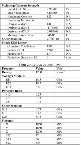
Table 1 Plate Material AL6061-T6 (Ansys source)
Property Value Unit
Density 2703 Kg/m3
Parameter Quadratic S2 0 s/m
Table 2 KEVLAR-29 (hoof 1999)
Property Value Unit
Density 1230 Kg/m3
Young’s Modulus
E11 18.5 GPa
E22 18.5 GPa
E33 6.0 GPa
Poisson’s Ratio
v12 0.25 v13 0.33 v23 0.33 Shear Modulus
G12 0.77 GPa
G13 5.43 GPa
G23 5.43 GPa
Strength
X 1850 MPa
Y 1850 MPa
Z 1200 MPa
S12 77 MPa
S13 543 MPa
S23 543 MPa
All properties required for FEM simulation are shown in table 1, 2 and 3 respectively. For tool simple material model is considered and treated it as rigid material.
Table 3 Tool: Structural Steel
Property Value Unit
Density 7850 Kg/m3
Young’s Modulus 2E+11 Pa
Poisson’s Ratio 0.3
Bulk Modulus 1.66E+11 Pa
Shear Modulus 7.692E+10 Pa
Sp. Heat 434 J/kg C
VI.
RESULT
AND
DISCUSSION
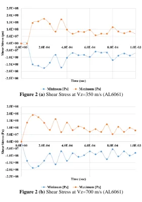
Figure 2 (a) Shear Stress at Vz=350 m/s (AL6061)
Figure 2 (b) Shear Stress at Vz=700 m/s (AL6061)
As shown in figure 2 it was clear that development of shear stress is high at 700 m/s velocity range for both materials used in FEM simulation. But max shear stress development was obtained in Al6061-T6 plate as shown in figure 2 (b).
As we know Al6061 has very high density than KEVLAR material and because of it AL6061 has more resistant than KEVLAR but elastic limit of KEVLAR was more than AL6061 and try to deform less than Al6061 which was shown clear in figure 3.
Figure 3 (a) Equivalent Stress for AL6061-T6
In this study it was try to observe velocity decrement of tool impactor on various velocities ranges at different material plates. From figure 4 (a) it was shown that when tool impact with 700 m/s velocity at test plate made of Al6061-T6 was deform at 1.0E-04 sec from initial time of impact of tool and after that tool get uniform velocity in same direction.
Figure 4 (a) AL6061-T3 Plate Deformation at Tool velocity 700 m/s
Figure 4 (b) AL6061-T3 Plate Deformation at Tool velocity 350 m/s
From analysis of figure 4(b) it was shown that tool was try to deform plate at velocity range of 350 m/s but after 3.0 E-04 sec tool reflect back in current direction and gain uniform velocity till end time. Here tool cannot make hole in test plate like previous velocity range.
Figure 4 (d) KEVLAR-29 Plate Deformation at Tool velocity 350 m/s
Tool velocity decrement analysis for KEVLAR-29 material was shown in figure 4 (c) and 4 (d). It was shown that for both velocity ranges of tool was make holes in test plate made of KEVLAR composite material. Due to high elastic limit of material more deformation was shown rather than Al6061 made plate.
Figure 5 (a) AL6061-T6 Deformation rate at Vz=350 m/s
Figure 5 (b) AL6061-T6 Deformation rate at Vz=700 m/s
VII.
CONCLUSIONS
A finite element model using Ansys Autodyan was developed to simulate the high-velocity impact reaction of anAL6061-T6 and Kevlar29 composite plate. The interaction between the impactor tool and the laminate was simulated using a surface-to-surface eroding contact algorithm. Numerical analyses were conducted at two impact velocities of 350 and 700 m/s of a structural steel impactor. From this study it was clear that impact velocity was dependent on impactor mass also. The present finite element model also successfully simulated the progressing damage from the initial impact to the final penetration of the composite plate.
REFERENCES
[1]. Meyers, M. A., (1994) “Dynamic behavior of Materials”, John Wiley & Sons, ISBN 0-471-58262-X. [2]. Finite Element Simulation of Ballistic Impact in Ballistic Studies , MSME thesis, Lexington, KY 2003. [3]. Ipson, T.W. and R.F. Recht. “Ballistic-penetration Resistance and its Measurement.”Vol. 15, pp
247-256, 1975
[4]. “Penetration Equations Handbook for Kinetic Energy Penetrators.” Joint Technical Coordinating Group for Munitions Effectiveness, 61 JTCG/ME-77-16, Oct. 1985.
[5]. Zukas, Jonas A. “Survey of Computer Codes for Impact Simulation.” High Velocity Impact Dynamics. Ed. Jonas A.Zukas. New York: John Wiley and Sons, pp. 593-714, 1990.
[6]. Chen, E.P. “Finite element Simulation of Perforation and Penetration of Aluminum Targets by Conical-Nosed Steel Rods.” Mechanics of Materials, Vol. 10, 1990.
[7]. Bamman, D.J., “Prediction of Ductile Failure in Metal Structures.” Applied Mechanics Department, Sandia National Laboratory.
[8]. Barrett, David M. “A Study of the Modeling of Ballistic Impact and Penetration of Thin Plates Using DYNA-3D.”M.S.M.E. Thesis, Mechanical Engineering Dept., University of Washington, Seattle, WA, 1993.
![Figure 1 (A) Overview of Explicit Dynamics Methodology [Mayer & Zukas]](https://thumb-us.123doks.com/thumbv2/123dok_us/1378507.1648353/2.595.175.422.79.310/figure-overview-explicit-dynamics-methodology-mayer-zukas.webp)