ISSN (Online): 2320-9364, ISSN (Print): 2320-9356
www.ijres.org Volume 1 Issue 6 ǁ Oct 2013 ǁ PP.01-08
Optical Fiber Device For Coupling A Composite-Type Optical
Fiber Scope And Pulse Laser Processing For Plant Maintenance
Yukihiro Yonemoto
1, Akihiko Nishimura
2, Kiyoshi Oka
2, Yukihiro Shimada
31
(Priority Organization for Innovation and Excellence, Kumamoto University, Japan)
2(Quantum Beam Science Directorate, Japan Atomic Energy Agency, Japan) 3(Applied Laser Technology Institute, Japan Atomic Energy Agency, Japan)
ABSTRACT
:
An optical fiber coupling device for plant maintenance was developed. Pulse laser processing with the coupling device can serve three functions: spectral analysis, laser processing, and visual observation. All of these functions can be operated remotely via a single composite-type optical fiber scope. The optical fiber scope enables both laser energy delivery and target image transmission with simultaneous counter-propagation, which can make a probing device very compact. Therefore, this device would permit laser processing in a narrow space, allowing in situ monitoring for plant maintenance. The functionalities of the coupling device for cleaning a metal surface and for remote spectral analysis were tested and reported. Finally, possible applications and desired technologies for the coupling device were discussed, including its use in a nuclear power plant sensing system for detecting seismic vibration.Keywords
– surface cleaning, optical fiber observation, pulse laser, spectroscopyI.
INTRODUCTION
High energy from a pulse laser over a small space generates ablation plasma. Ablation plasma generates a shock wave that propagates in a material, improving the mechanical properties of the material around the point of irradiation. These characteristics are used in industrial applications such as surface cleaning [1] and micro fabrication [2], and in medical applications such as microsurgery for removing biological tissue[3]. However, in nuclear engineering, the only application of practical use is laser peening, which prevents stress corrosion cracking (SCC) in nuclear power plants [4, 5].
Although the pulse laser is not widely used in nuclear engineering, Japan Atomic Energy Agency (JAEA) has sought to find safety technology applications for it in nuclear power reactors, such as for the SCC problem and for the fabrication of a fiber Bragg grating (FBG) sensor [6]. In the study of the SCC problem, an oxide layer is removed by a picosecond or femtosecond pulse laser on a stainless steel plate in an air environment, ultimately improving the tensile residual stress of the stainless surface. In the fabrication of the FBG sensor, a femtosecond pulse laser is focused at the center of a fiber core made from fused quartz, which causes a periodic refractive index modulation in the core fiber. In the future, the FBG sensor will be used in strain and temperature sensors for nuclear piping to monitor seismic events.
In addition to the above research, a medical device[7-9] and laser welding technology for the repair and maintenance of steam generators[10] are being developed at JAEA through use of a composite-type optical fiber scope[11]. The composite-type optical fiber scope can transmit both the laser and image. However, at the present time, the research focuses on the use of continuous wave (CW) lasers only. If the pulse laser could be applied to the composite-type optical fiber scope, the unique phenomena of the pulse laser, such as the plasma ablation and the shock wave induced by the plasma ablation, could be used in the research. Thus, various applications such as surface treatments and laser processings would be made possible by taking advantage of the thermal effects of the pulse laser.
II.
D
ESIGN OF THE ADVANCED OPTICAL FIBER COUPLING DEVICE2.1 Constitution of the coupling device for pulse laser
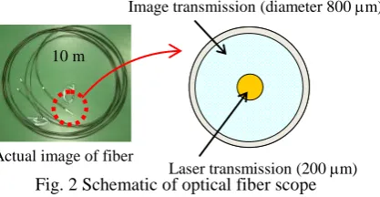
Figure 1 shows a schematic of the coupling device for a pulse laser. Optical components and a CCD camera are installed on an optical board of size 400 × 500 mm. The pulse laser used in this device is a Nd:YAG laser. The repetition rate, pulse duration, and wavelength are 10 Hz, 4–6 ns, and 532/1064 nm, respectively. The coupling device is equipped with an optical fiber scope and a spectroscope. The optical fiber scope consists of two types of glass fibers[11] as shown in Fig. 2. One type, located at the core of this fiber scope, transmits the pulse laser. The diameter of its core fiber is about 200 m. The other type, which surrounds the core fiber, transmits the image from the front edge of the fiber scope. The image fiber consists of 20,000 glass fibers, allowing a surface of a target image to be transmitted through the image fiber with high clarity and resolution. The laser and spectroscope are controlled by a pulse generator (DG535).
Fig. 1 Schematic of the coupling device (the dashed and solid lines are passes of the pulse laser and target image, respectively): (a, b) mirror for 1064 nm, (c–f) condenser lens, (g) half mirror, (h) CCD camera, (i) total
reflection mirror, (j) pulse generator.
Fig. 2 Schematic of optical fiber scope
2.2 Transmission of pulse laser into the optical fiber scope
The laser pulse from the laser source is reflected in dielectric coating mirrors (a) and (b) at 45° in the coupling device as shown in Fig. 1. Then, the pulse laser is focused by the condenser lens (c) on the core fiber of the optical fiber scope, whose surface has an antireflective coating. Next, the laser is delivered to the other end of the optical fiber scope and irradiated on the target through the condenser lens (f). Here in this device, a second harmonic generation at 532 nm, which is generated by a nonlinear crystal, is mainly used as a guide laser to precisely set an irradiation spot from the pulse laser to the core fiber. The edge face of the core fiber in the coupling device can be observed by CCD camera (h) through the condenser lens (e). The light of the 532 nm guide laser is also captured on the CCD camera. Thus, from both the guide laser and core fiber images on the CCD camera, the position of the core fiber can be adjusted by using a microstage.
2.3 Spectroscopy in the optical fiber coupling device
The optical fiber scope can capture the target image from the edge front of the fiber scope. In the coupling device, the image captured by the optical fiber scope is divided into two passes by the half mirror (g). One pass leads to the CCD camera, and the other leads to a spectroscope through the total reflection mirror (i) and condenser lens (d) as shown in Fig. 1. Therefore, if the pulse laser is focused on the surface of the target metal, plasma emission from the target surface is captured, and spectral analysis is possible.
Image transmission (diameter 800 m)
Laser transmission (200 m) Actual image of fiber
10 m (b) (a) (g) (e)
(d) (i)
(h) (c)
Spectroscope Optical fiber scope
Target (f)
Plasma emission Laser source
532/1064 nm
Pulse generator
To laser source
III.
E
XPERIMENTSA surface cleaning, with an observation of emission plasma of materials by the pulse laser, is performed. In this experiment, as a first step, some metals are irradiated by the pulse laser to evaluate the ability of the coupling device. The metals are copper, aluminum, and SUS304. Then, STPA24 with and without an oxide layer are evaluated. Here, STPA24 is a low-chromium-content steel and a piping material used in an actual nuclear power plant. The wavelength of the pulse laser is 1064 nm. The laser energy is carefully adjusted at about 3 mJ, which corresponds to 2.2 J/cm2. The transmission efficiency of pulse energy through the optical fiber scope is about 98%. In this experiment, a long wavelength-pass filter is set between the laser source and the coupling device so as not to detect 532 nm laser peak on spectra.
3.1 Spectral intensity of metals
Figure 3 shows results of spectral intensities of some metals in an air environment. Figures 3(a)–(d) are copper, aluminum, stainless steel (SUS304), and mirror-finished STPA24, respectively. Each spectral distribution exhibits a different profile, and some specific spectral lines are observed. For copper [Fig. 3(a)], two specific lines are observed at 510.55 and 576.54 nm, respectively. These lines would correspond to Cu(I) (510.554 nm) and Cu(III) (576.856 nm), respectively[12,13]. On the other hand, the spectral line for aluminum is observed at 396.4 nm in the local region of Fig. 3(b). This would correspond to Al(I) (396.2 nm)[12,13]. The spectral profiles in Figs. 3(c) and (d) are similar, with two specific lines appearing around 427 and 589 nm in both figures. This similarity may occur because the components of SUS304 and STPA24 are similar to each other[14]. These two spectral lines are discussed in the next section, including the spectral profile of STPA24 with the oxide layer. At any rate, our optical fiber coupling device has a possibility for spectral analysis and can identify types of metals via a single optical fiber scope.
Figure 3 Spectral intensities of some types of metals: (a) copper, (b) aluminum, (c) stainless steel (SUS304), (d) STPA24 (mirror finished).
3.2 Surface cleaning
To evaluate the capability of the coupling device for surface cleaning, an oxide layer of STPA24 is irradiated by the pulse laser through the coupling device. Here, the oxide layer is formed by heating the STPA24 in air up to 600°C, the operating temperature of the sodium-cooled Fast Breeder Reactor. This heating covers the surface of the STPA24 with an oxide layer.
Figure 4 shows the spectral profile of the oxide-coated STPA 24. From this figure, two specific lines are observed around 589 and 766 nm. Compared with Fig. 3(d), the spectral profile is obviously different. The
400 600 800 1000
0 500 1000 (a) Wavelength [nm] In ten sit y [c o u n ts] 510.55nm
576.54nm Local
region
400 600 800 1000
0 5000 10000 15000
350 400 450 500 0 1000 2000 (b) Wavelength [nm] In ten sit y [c o u n ts] 396.4nm
400 600 800 1000
0 1000 2000 (d) Wavelength [nm] In ten sit y [c o u n ts] 589.26nm 427.96nm
400 600 800 1000
spectral line around 427 nm does not appear in this profile. In addition, a steep spectral line around 766 nm is observed. However, the spectral line around 589 nm is observed in Fig. 3(d). This line is also observed in SUS304 [Fig. 3(e)]. A basic component of SUS304 [Fig. 3(c)] and STPA24 is iron[14]. Therefore, the spectral line around 589 nm may correspond to Fe(I) (588.94 nm)[13]. On the other hand, considering that the surface of STPA24 in Fig. 4 is covered with the oxide layer, the spectral line around 766 nm may be O(II) (765.68 nm)[13]. The line around 427 nm, which does not appear in Fig. 4 but in Fig. 3(d), is a component under the oxide layer. In addition, the intensity of this line in Fig. 3(c) is stronger than that in Fig. 3(d). Therefore, the line around 427 nm is expected to be Cr(I) (427.60 nm)[13], which is the second most common element in SUS304 and STPA24[14].
Figure 4 Spectral distribution of oxide-coated STPA24.
Figure 5 shows the time series of overall spectral profiles of oxide-coated STPA 24 during irradiation at a fixed point. From this figure, spectral intensities around 766 nm, which may be related to O(II), gradually decrease as the pulse number increases. Finally, the peak near 766 nm disappears. Figures 5(a) and (b) show a surface image of STPA24 before and after the pulse laser irradiations. In Fig. 5(b), the irradiation spot (of diameter ~400 m) exhibits a metallic sheen. It is found that the oxide layer is removed at the irradiation spot. From the results in these figures and discussion in Fig. 4, the peak near 766 nm would be expected to be oxygen atoms, and reduction of this peak may indicate oxide layer removal.
The optical fiber coupling device can observe not only the plasma spectral intensity but also a real-time image during the laser irradiation process. Figure 6 shows the observed real-time image of the surface cleaning. An actual surface image of STPA24 is shown in Fig. 6(a). As soon as the position to be cleaned is determined, the position is fixed and the core fiber is overlapped just like a sight on a target, which is shown in Fig. 6(b). Next, the pulse laser irradiates the target surface as shown in Fig. 6(c). Finally, the plasma from the irradiation is transmitted to the spectrometer through the image fibers, and spectral analysis is performed. This result proves that performing the sequence of the visible laser cleaning process in a narrow space with the target image is possible with the coupling device. For maintenance engineering applications, this result is very important.
Fig. 5 Time series of spectral distribution of oxide-coated STPA24: (a) surface image before the irradiation, (b) the image after irradiation for 4 s.
400 600 800 1000
0 10000 20000
Wavelength [nm]
In
ten
sit
y
[c
o
u
n
ts]
0pulse 10pulses
15pulses
20puses
40pulses
(a)
(b)
400m
400 600 800 1000
0 1000 2000
Wavelength [nm]
In
ten
sit
y
[c
o
u
n
ts]
589.38 nm
Fig. 6 Observed image of oxide layer on STPA24 surface through the optical fiber scope: (a) surface image of STPA24, (b) image before laser irradiation, (c) image during laser irradiation.
The scale bar is for the observed image.
3.3 Remote laser processing: integration time and spectral intensity
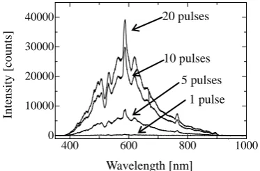
In the above experiments, an objective lens is used for the fundamental functioning of the coupling device. However, in an actual on-site situation, far-distance work must be considered. Therefore, in this section, the possibility for far-distance work is evaluated. Figure 7 shows spectral profiles of STPA24 using an objective lens and a plane-convex lens (f = 50 mm). Figure 7(a) shows the plane-convex lenses, and Figure 7(b) shows the objective lens. From these results, it is found that the objective lens enables sensitive measurement of spectral intensity of the plasma. This result is very important in a spectral analysis of far-distance capability by the optical fiber coupling device. Figure 8 shows some cases of plasma distributions (STPA24) using the plane-convex lens in which some cases of integration time in the spectroscope are performed. The number of pulses are 1, 5, 10, and 20. Each profile represents the integrated intensity of each pulse number. From this result, the measured intensity of the plasma increases as the integrated pulse number increases. Measurable intensities are obtained in 5, 10, and 20 pulses. Therefore, if a spectral analysis of far distance is needed, the spectral intensity can be controlled not only by the combination of lenses but also by the integration time of the spectroscope.
Fig. 7 Intensity profile of STPA24: (a) plane-convex lens, (b) objective lens.
Fig. 8 Intensity profiles of integration times 500 m
(a) (b)
(c) Image transmission
Laser transmission
400 600 800 1000
0 5000 10000
Wavelength [nm]
In
ten
sit
y
[c
o
u
n
ts]
(b)
400 600 800 1000
-500 0 500 1000
Wavelength [nm]
In
ten
sit
y
[c
o
u
n
ts]
(a)
400 600 800 1000
0 10000 20000 30000 40000
Wavelength [nm] 1 pulse 5 pulses 10 pulses 20 pulses
In
ten
sit
y
[c
o
u
n
IV.
A
PPLICATION FOR THE NUCLEAR POWER PLANTThe combination of pulse laser processing, surface imaging, and plasma spectroscopy was described in the previous section. Here novel applications for plant maintenance are discussed.
4.1 Laser direct bonding of glass
At the present time, we are developing a FBG sensor system for long-term monitoring of nuclear piping. In the system, installation of an FBG sensor on the surface of the piping is necessary.
In general, use of a thermally resistant adhesive will be a practical approach for the installation of the FBG sensor on the nuclear piping. In our recent study[17], an adhesion test of the FBG sensor on STPA24 was performed for evaluating the adhesion under high temperatures and for measuring the temperature of the test material. In the experiment, the FBG sensor was woven into carbonaceous fibers to ensure the flexibility of the FBG sensor, and a coat of adhesive was applied between the carbonaceous fibers and the STPA24 surface. However, the result was that the carbonaceous fibers broke because the rates of thermal expansion between the adhesive and the metal surface were different. Although the adhesive is the most practical tool at present, there are still problems to be solved. There is a limit on the thermal resistance of adhesive materials, even if the adhesive is considered thermally resistant. In the field of electronics[15,16], a means of direct bonding has been developed and applied to some industrial applications.
A femtosecond pulse laser is focused at the interface of transparent materials. Then, the interfaces of two different materials are welded owing to nonlinear adsorption and the resulting energy deposition. Finally, two materials are bonded at the interface. Direct bonding of the materials without using an intermediate material such as adhesive would eliminate the problems encountered in the case of the adhesive, because with direct bonding, the materials can utilize their own mechanical and thermal properties. Thus, the limit of the thermal resistance can be ensured to be within the melting temperature of the materials. Therefore, direct bonding is an ideal technique. If the installation system of an FBG sensor for seismic events is realized on the basis of our coupling device, at least the system will enable prompt action to ensure safety in response to such an event because it is an on-site and continuous monitoring system for nuclear piping. Direct bonding is mainly performed by a femtosecond laser; however, use of a nanosecond pulse laser is economical and practical. In this section, we show an example of direct bonding in a desired technology for the optical coupling device of the future.
Figure 9 A schematic of the test section of a direct bonding: (a) side view, (b) top view.
Figure 10 Irradiation point between glass slide and cover glass
This experiment utilized a Nd:YAG laser of wavelength 1064 nm. Although the ideal goal of direct bonding is the bonding of various materials such as glass–metal, glass–glass bonding is performed as a first step. Then, to avoid a defect in the fiber core, the pulse laser irradiates the target directly without optical fiber scope transmission. Figure 9 shows a schematic of the test section of the direct bonding. A cover glass is sandwiched
Cover glass Copper plate
Silicone rubber (t = 1 mm) Top plate:
Glass slide (t = 1 mm) Pulse laser
Bottom plate: Glass slide (t = 1 mm)
(a)Side view
5 mm
5 mm 12 mm
12 mm
Copper plate Cover glass
(t = 0.15 mm)
(t = 0.1 mm)
(b)Top view
Cover glass
Copper plate
Silicone rubber Glass slide (Top plate)
Glass slide (Bottom plate)
between two glass slides. The two glass slides are held tightly with screws. The pulse laser is focused at the interfaces between the glass slides and the cover glass as shown in Fig. 10. An objective lens is used, and the spot diameter is about 100–200m.
Figure 11 shows the glasses after the direct bonding. The laser irradiated five points at the interface between the cover glass and glass slides. The pulse numbers at each point are 11 pulses. When the laser is focused at the interface between two glasses, plasma emission occurs with brilliant white color. Figure 12 shows images of one of the five irradiation spots at (a) the surface of the glass slide that faces the cover glass, (b) interface between the slide and cover glass, and (c) surface of the cover glass. Especially, at the center of the irradiation spot in (b), a small bubble is observed as shown in Fig. 12(d). This would be an evidence of the glass melting. In this experiment, three laser energies (1.5, 1.81, and 2.3 mJ) are used. The results show that bonding strength depends on the laser energy. The maximum strength, about 0.42 MPa, is obtained at 1.81 mJ. At 2.3 mJ, the strength is about 0.26 MPa, but at 1.5 mJ, bonding cannot be achieved. Here, the contact area of the two glasses for measurement of bonding strength is roughly estimated by measuring the size of each irradiated point at the interface between cover glass and glass slide. Total contact area is obtained by summing each area of the irradiated point. The reduction in strength for the 2.3 mJ energy may be related to a crack in the glass surface around the irradiation spot. Actually, cracks in the glass increase as the laser energy increases.
Figure 11 Actual image of glass slide and cover glass after direct bonding.
Figure 12 Magnified view of the irradiation spot on glass surfaces: (a) surface of glass slide, (b) interface between cover glass and glass slide, (c) surface of cover glass,
(d) small bubble at the center of irradiation spot (b).
4.2 Potential of the coupling device at Fukushima nuclear power plant
From the results already discussed, pulse laser processing with the coupling device can serve three functions: spectral analysis, laser processing, and visual observation. The most unique and important features of this device are that all of these functions can work via a single optical fiber scope and that remote operations of their functions are possible. In nuclear engineering, this technology could be useful in environments too highly radioactive for utility workers.
On March 11, 2011, the Great East Japan Earthquake assaulted the nuclear power plant of Fukushima Daiichi and generated the tsunami waves that hit five nuclear power plant sites[18]. At all sites, the nuclear power plants were of the boiling water reactor (BWR) type. Because of the tsunami, Fukushima Daiichi lost much of its safety equipment and all electrical power. This caused a loss of cooling at nuclear reactor units 1, 2, 3, and 4. Finally, meltdown occurred in units 1, 2, and 3, which led to hydrogen explosions in units 1, 3, and 4. Hereafter, a decommissioning plan spanning 40 years will be executed. For reactor decommissioning, we need to be able to observe the situation inside the container of each unit, to determine such conditions as molten fuel
10 m
100 m 100 m
100 m
(a) (b)
(c) (d)
10 m
100 m 100 m
100 m Cover glass
debris and damaged core structure. Therefore, we plan to combine multifunctions such as laser processing, surface imaging, plasma spectroscopy, and so on. Only a brand new device will enable such observation and give precise confirmation of the interior environment to ensure a smooth decommissioning process.
V.
C
ONCLUSIONAn advanced optical fiber coupling device for the maintenance of nuclear power plants has been developed by combining three existing technologies: pulse laser processing, visual observation through an optical fiber scope, and laser-induced breakdown spectroscopy. The fundamental functions of laser cleaning and direct bonding have been evaluated. In surface cleaning, a nanosecond pulse laser was irradiated on oxide-coated STPA24. Spectral analysis of the irradiation revealed that the oxide layer can be removed within 5 s and that two specific peaks are observed at wavelengths 588 and 767 nm. The intensities of these two peaks gradually decrease over time. This result will become a measure of the degree of oxide layer removal.
A novel application, to install an FBG sensor on nuclear piping, was discussed. The realization of an on-site monitoring system for coolant pipe lines using the FBG sensor will enhance safety for the long-term operation of nuclear power reactors. Especially, applying the system to ageing light-water-reactors is desired for safer operation. In the near future, a brand new probing system that includes some laser technologies such as laser direct bonding, laser processing, and spectroscopy will be applied not only in nuclear engineering for reactor decommissioning but also in other fields such as laser low-invasive surgeries[19] and maintenance for petrochemical complex.
VI.
A
CKNOWLEDGEMENTThe experimental work was carried out when the representative author belonged to Japan Atomic Energy Agency. A part of the discussion has been completed after he moved to Kumamoto University. The authors deeply thank to the participants.
Reference
[1] A.-C. Tam, H.-K. Park, C.-P. Grigoropoulos, Laser cleaning of surface contaminants, Appl. Surf. Sci., 127-129(1998) 721. [2] S. Juodkazis, S. Matsuo, H. Misawa, V. Mizeikis, A. Marcinkevicius, H.-B. Sun, Y. Tokuda, M. Takahashi, T. Yoko, J. Nishii,
Application of femtosecond laser pulses for microfabrication of transparent media, Appl. Surf. Sci., 197-198:705, 2002. [3] Y. Paulus, D. Palanker, M. S. Blumenkranz, Short-pulse laser treatment: redefining retinal therapy, Retinal Physician, 7: 54,
2010.
[4] M. Obata, Y. Sano, N. Mukai, M. Yoda, S. Shima and M. Kanno, Effect of laser peening on residual stress and stress corrosion cracking for typ. 304 stainless steel: Proc. 7th Int. Conf. Shot peening ICSP-7, Warsaw, 1999, 387-394.
[5] Y. Sano, Residual stress improvement on metal surface by underwater irradiation of high-intensity laser, Journal of Japan Laser Processing Society (in Japanese), 9: 163, 2002.
[6] A. Nishimura, Y. Shimada, Developing maintenance technologies for FBR's heat exchanger units by advanced laser processing :
Proc. of ICONE19 19th Int. Conf. Nuclear engineering, Chiba, Japan,2011, ICONE19-43943.
[7] T. Seki, A. Naganawa, K. Oka, T. Chiba, 10.Laser irradiation control of fetal endoscopic surgery for twin-twin transfusion syndrome (-Verification of blood-flow interception by in vivo experiment-), SICE Trans. on industrial Application (in Japanese),
9: 70, 2010.
[8] K. Oka, T. Seki, A. Naganawa, H. Yamashita, K. Kim, T. Chiba, The development of a composite-type optical fiberscope system for fetoscopic laser photocoagulation of chorionic plate anastomosing vessels (FLPC) , Min. Inv. Therapy Allied Tech., 19: 94, 2010.
[9] K. Oka, T. Seki, A. Naganawa, K. Kim, T. Chiba, A novel ultrasmall composite optical fiberscope, Surg. Endosc., 25: 2368, 2011.
[10] A. Nishimura, T. Shobu, K. Oka, T. Yamaguchi, Y. Shimada, O. Mihalache, A. Tagawa, T. Yamashita, Development of inspection and repair technology for the micro cracks on heat exchanger tubes, Journal of Japan Laser Processing Society, 17: 207, 2010.
[11] K. Oka, A. Nishimura, T. Seki, T. Akatsu, T. Yamashita, 6.Development of a Laser Processing Head Using a Composite-type Optical Fiberscope to Inspect and Repair 1-inch Heat Exchanger Pipes, Maintenology (in Japanese), 8: 37, 2010.
[12] S. S. Ciobanu, C. Negutu, M. Stafe, I. Vladoiu, V. Pais, V. Stancalie, N. N. Puscas, Spectroscopic studies of laser induced aluminium and copper plasmas in air: 35th EPS Conference on Plasma Phys., Hersonissos, 2008, ECA Vol. 32D, P-5. 144(1-4).
[13] National institute of standards and technology, U.S.A., Electronic
database,http://physics.nist.gov./PhysRefData/ASD/lines_form.html
[14] S. Hattori, Effects of Impact Velocity and Droplet Size on Liquid Impingement Erosion: Proc. of Int. Symposium the Ageing Management & Maintenace of Nuclear Power Plants, 2010, 58 -71.
[15] Y. Ozeki, T. Inoue, T. Tamaki, H. Yamaguchi, S. Onda, W. Watanabe, T. Sano, S. Nishiuchi, A. Hirose, K. Itoh, Direct Welding between Copper and Glass Substrates with Femtosecond Laser Pulses , Appl. Phys. Express, 1: 082601-1, 2008.
[16] K. Cvecek, I. Alexeev, I. Miyamoto, M. Schmidt, Defect formation in glass welding by means of ultra short laser pulses, Phys. Procedia, 5: 495, 2010.
[17] Y. Shimada, A. Nishimura, Development of structural health monitoring sensors by optical fiber Bragg grating: The 12th International Symposium on Laser Precision Microfabrication LPM2011, Takamatsu, Japan, 2011, We-P-17.
[18] IAEA: The Great East Japan Earthquake Expert Mission, IAEA International Fact Finding Expert Mission of the Fukushima Dai-ichi NPP Accident following the Great East Japan Earthquake and Tsunami, 24 May-2 June 2011(IAEA Mission report, 2011) [19] K. Oka, T. Seki, A. Nishimura, Medical application of composite-type optical fiberscope, OYO BUTURI(in Japanese), 80: 1069,

![Figure 4 Spectral distribution of oxide-coated STPA24. Wavelength [nm]](https://thumb-us.123doks.com/thumbv2/123dok_us/7802124.1660600/4.595.182.397.205.335/figure-spectral-distribution-oxide-coated-stpa-wavelength-nm.webp)