Design of Single and Double Balanced Gilbert
Cell Mixer using CMOS Processing Technology
Jinal Shah Nimesh Prabhakar
PG Student Assistant Professor
Department of Electronics & Communication Engineering Department of Electronics & Communication Engineering LJ Institute of Engineering and Technology Ahmedabad,
India
LJ Institute of Engineering and Technology Ahmedabad, India
Abstract
This paper presents down conversion single and double balanced mixer. Mixer is designed with the help of CMOS Processing technology. Double balanced mixer consists of parallel connection of two single balanced mixer. Double balanced mixer topology has better port to port isolation compared to single balanced mixer. Various parameters are measured on mixer topology that is conversion gain and linearity parameters such as 1 dB compression point and third order intercept point. A comparison is made between single and double mixer and it shows that conversion gain and linearity parameters are improved in double balanced mixer.
Keywords: Single Balanced Mixer, Double Balanced Mixer, Conversion Gain, 1Db Compression Point, Third Order Intercept Point
________________________________________________________________________________________________________
I. INTRODUCTION
In a receiver system down conversion mixer is a key building block. It determines system linearity, noise figure and performance of adjacent block. RF Mixers are 3-port active or passive devices. They are designed to yield both, a sum and a difference frequency at a single output port when two distinct input frequencies are inserted into the other two ports.
Fig. 1: RF Mixer [10]
The two signals inserted into the two input ports are usually the Local Oscillator signal, and the incoming (for a receiver) or outgoing (for a transmitter) signal. To produce a new
Frequency (or new frequencies) a nonlinear device is required.
RF Mixer is fundamentally a device, which is shifting a signal from one frequency to another, keeping the properties of the initial signal (phase and amplitude), and therefore doing a linear operation. An LTI circuit cannot do frequency translation, hence either a time varying parameter or a non-linearity is used.
Along with the sum and difference of frequencies, it also produces harmonics of input frequency, LO frequency and their intermodulation products. These harmonics increase non- linearity of mixer. The basic aim while designing mixer is to suppress these harmonics.
RF Mixers use two operation mechanisms:
Switching or sampling is a time-varying process. This method is preferred because has fewer spurs and can provide higher linearity.
II. SINGLE BALANCED MIXER
A single balanced have differential LO signal but single ended RF signal. Active mixers have basically three functions: - Convert RF voltage to a current.
Steer the RF current by LO. Convert IF current to voltage.
Thus active mixer incorporate switching by voltage to current and current to voltage conversion. Here input transconductance and output transresistance can have large values yeilding high conversion gain.
As shown in the figure RF signal varies the drain current at M1. M2 and M3 function as switching pair driven by LO. Thus the drain current of M1 is multiplied by the square wave of LO. The product is routed to the two resistors R1 and R2 by the switching pair alternatively. The proper choice of MOS width by length ratio will affect the drain current from the transcoductance stage.
The width by length ratio of the mixing stage MOS are kept half of the transconductance stage. The gain of the mixer is given by: -
gain = 2 πgmRd
Here the coefficient 2⁄π comes due to switching. Increasing the current through transconductance stage will increase gm and
hence the gain of mixer. To increase current in transconductance stage we will also have to increase current through mixing stage which will increase noise figure of the mixer. We have to choose current through the mixer as a tradeoff between noise performance and gain.
Fig. 2: Block diagram of single balanced mixer [11]
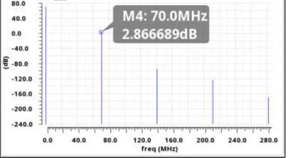
III. SIMULATION RESULTS OF SINGLE BALANCED MIXER
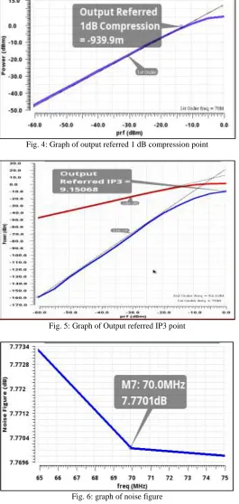
Fig. 4: Graph of output referred 1 dB compression point
Fig. 5: Graph of Output referred IP3 point
Fig. 6: graph of noise figure
IV. DOUBLE BALANCED GILBERT CELL MIXER
Fig. 7: diagram of double balanced Gilbert cell mixer [11]
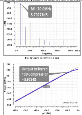
V. SIMULATION RESULTS OF DOUBLE BALANCED GILBERT CELL MIXER
After the design of single balanced mixer simulation is performed on design and various parameters are obtained.
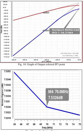
Fig. 10: Graph of Output referred IP3 point
Fig. 11: graph of noise figure
VI. COMPARISON
Table 1 shows comparison between single and double balanced mixer and it shows that all parameters are improve in double balanced mixer.
Table - 1
Comparison between two mixers
Parameter Single balanced mixer Double balanced mixer
Conversion gain (dB) 2.86 8.70
Output referred 1 db compression point (dBm) -0.93 5.97 Output referred IP3 point (dBm) 9.15 16.77
Noise figure (dB) 7.77 7.53
VII.CONCLUSION
REFERENCES
[1] Kumar Munusamy and Zubida Yusoff, “A high Linear CMOS Down Conversion Double Balanced Mixer”,IEEE-International Conference on Semiconductor Electronics, pp. 985-990, 2013.
[2] Ranjendra D. Kamphade and Santosh B. Patil, “A 2.4 GHz Double Balanced Differential Input Differential Output Low power High Gain Gilbert Cell Down Conversion Mixer In TSMC 180nm CMOS RF Process”, IEEE- International Conference on Electronics and Communication System, pp. 1187-1193, 2015. [3] Hanen Thabet and Mohamed Masmoudi, “Design optimization methodology of CMOS direct Down-conversion Mixer for Wireless Sensors”, IEEE-
International Conference on Design & Technology of Integrated System, pp. 1-6, 2008.
[4] Jiming Jing and David M Holburn, “Design and Analysis of A Low-Power Highly Linear Mixer”, IEEE-International Conference on Circuit theorey and Design, pp. 675-678, 2009
[5] Jacob Phil, Kare Tais and Erik Bruan, “Direct Down Conversion with Switching CMOS Mixer”, IEEE ISCAS , pp. 117-120, 2001.
[6] Amel Neifer, Ghazi Bouzid, Mohamed Masumoudi, “Improvement of the Linearity and Conversion Gain of an Ultra Wideband Up –Conversion Mixer in CMOS 0.18 um Technology”IEEE- International Conference on Systems, Signals & Devices, pp. 1-5, 2015
[7] Shuai Huang, Xinnan Lin, Yiqun Wei, Jin He, “Derivative Superposition Method for DG MOSFET Application to RF Mixer”,IEEE -International Conference on Quality Electronics Design, pp. 361-365, 2010.
[8] MeysamAsghari, Mohammad Yavari, “A high IIP2 and IIP3 CMOS down conversion Active mixer”, IEEE Iranian Conference on Electrical Engineering (ICEE), pp. 351-354, 2014.
[9] “Microwave Engineering” by David M. Pozar, 4th edition, Wiley Publications
![Fig. 1: RF Mixer [10]](https://thumb-us.123doks.com/thumbv2/123dok_us/7805121.1661336/1.612.177.437.386.568/fig-rf-mixer.webp)