A Language to Enable Distributed Simulation of
Extended Queueing Networks
∗
Daniele Gianni and Andrea D’Ambrogio
University of Rome TorVergata, Dept. of Computer Science, Rome, Italy {gianni, dambro}@info.uniroma2.it
∗ Work partially supported by funds from the FIRB project “Performance Evaluation of Complex Systems: Techniques Methodologies and Tools” and by the University of Rome TorVergata CERTIA Research Center.
Abstract — Distributed simulators are increasingly being used for their intrinsic advantages in terms of reusability, fault tolerance, performance, and geographic distribution. The development of a distributed simulator, however, requires significant investments in terms of effort if compared to the development of traditional local simulators. This paper introduces jEQN, a Java-based language that significantly reduces the extra effort needed to develop a distributed simulator of extended queueing networks (EQNs), by enabling simulator developers to build distributed simulators as they were to be locally executed. By use of jEQN, simulator developers are enabled to easily switch from a local to a distributed version of an EQN simulator by only modifying few statements of the given local simulator. Moreover, these statements can be easily inferred by a very intuitive graphical procedure. The paper illustrates both the jEQN architecture, based on a layered approach, and the implementation details that contribute to achieve the above mentioned advantages.
Index Terms — Software Architecture, Simulation Language, Distributed Simulation, High Level Architecture, Queueing Networks
I. INTRODUCTION
The development of a distributed simulation (DS) program is generally harder to carry out with respect to the development of a local simulator [1], because it is necessary to explicitly deal with communication, concurrency and synchronization issues [2], both between (i) the local and the distributed environment and among (ii) the distributed simulators that are part of the same DS program.
This paper specifically addresses simulation programs that represent and analyze system models specified by use of the extended queueing network (EQN) formalism [3].
Example simulation environments that can be used to build local simulation programs of EQNs are illustrated in [4] and [5]. On the other hand, currently available standards that give the necessary support to build DS programs (see, e.g., DIS [6] and HLA [7]) only deal with distributed infrastructures, in other words with the item (ii) previously mentioned, without addressing EQN simulation. Similarly, contributions that extend such standards to deal with both items (i) and (ii) can be found
in [8], [9], [10] and [11]; but they still fail to provide support in the EQN domain.
The main contribution of this paper is thus to provide an effective solution to such a lack of support. To achieve this objective, the paper introduces a language that can be transparently used to build local and distributed simulators of EQNs.
The proposed language, called jEQN, is Java-based and enables the developer of traditional (local) EQN simulators to easily build distributed simulators of EQNs. jEQN makes transparent use of the HLA DS standard, thus reducing both the level of required expertise in distributed simulation and the burden of learning how to use complex libraries that implement existing DS standards. It has been verified that the use of jEQN yields an effort saving of around 30% for developers with average HLA expertise, and up to 60% for HLA beginners [1].
This paper builds on a previous description of jEQN [1] and aims first to introduce a restyling of the jEQN architecture, by further reducing layer coupling, and second to provide the implementation details that contribute to achieve the above mentioned effort savings.
The paper is organized as follows: Section 2 briefly describes the overall jEQN layered architecture, while Section 3 illustrates the architecture details with the services provided at each layer and the relevant implementation details. For the sake of conciseness no description is given of the HLA standard, whose details can be found in [7].
II. JEQNLAYERED ARCHITECTURE
The jEQN architecture consists of four layers [1] that separate the jEQN program from the HLA-based DS infrastructure (denoted as layer 0), and a set of data interfaces that defines the common format of the data exchanged between the layers.
Layer numbering proceeds bottom-up, from layer 1 to layer 4 as follows:
Layer 4: the jEQN program
Layer 3: the jEQN simulation language (i.e., the
EQN primitives)
Layer 2: the execution container (i.e., the
Layer 1: the DES (discrete event simulation)
abstraction
Layer 0: the DS infrastructure (HLA in the paper
case)
The jEQN architecture makes use of the concepts of
simulation element and simulation engine. The simulation
elements represent the building blocks of a simulation, which can be grouped into entities, events exchanged by
such entities and ports/links through which events flow.
The simulation engine is instead responsible of the simulation initialization and execution.
III. DETAILS OF JEQNLAYERS
This section provides a detailed description of both the data interfaces between layers and of layers 1 through 4.
A. DATA INTERFACES
The data exchanged between the layers are:
• ComponentLevelEntity: defines the access
methods to local simulation entities
• Event: defines the access methods to the events,
which are scheduled between layers
• GeneralEntity: defines the interface for local and
remote simulation entities
• InputPort: defines the interface for input ports • Link: defines the interface for links
• Name: defines the interface for names
• OutputPort: defines the interface for output
ports
• Port: defines the interface for ports
• RemoteEntity: defines the interface for remote
simulation entities
• Time: defines the interface for the time.
The role of these data interfaces is to further reduce dependencies between layers by providing an abstract format for data exchange.
Data interfaces GeneralEntity, Event, InputPort, OutputPort and Link are logically related, as already
shown in [1].
Although [1] defines Ports, Links and Events as layer 2 internal components and not as cross-layer interfaces, their role and structure are similar and thus are not discussed further.
A.1 GeneralEntity
GeneralEntity is the interface for a logical process,
which is the building block of discrete event simulations carried out by use of the process interaction (PI) paradigm [12]. It is specialized into
ComponentLevelEntity and RemoteEntity; where the
former is used for a local process and the latter refers to a remote process. Both interfaces are to be implemented by Layer 2 developers.
It is worth remarking that the interfaces only define the data exchange format. The logical process has to be defined by the simulation language (layer 3) developers. They can thus define proper entities that will fit their application domain, e.g.: air traffic, computer network,
etc.; by implementing the interface
ComponentLevelEntity.
The interface ComponentLevelEntity is also the layer
2’s access point to layer 3 services, which means
ComponentLevelEntity implementations will provide the
actual implementation of Layer2ToLayer3 services. The interface RemoteEntity is independent of the
simulation domain as it does not include any simulation logic. In fact, its role is in proving a local reference to a remote simulation entity.
B. LAYER 1
The purpose of this layer is to provide an abstract view of DES mechanisms to layer 2.
In fact, by use of this layer, layer 2 does not deal with technology-specific issues and can thus be ported on several layer 0 technologies. In this case, the IEEE HLA technology [7] is used.
B.1 Layer 1 interface to layer 2
This interface consists of the implementation of five DES services as illustrated in Fig 1.
The service initDistributedSimulationInfrastructure
initializes the underlying distributed simulation environment and therefore it must be invoked before starting the execution of upper layers’ components. Although no parameter is reported in the signature of this service in Fig. 1, a configuration file parameter can also be included without significantly affect the current interface specification.
Analogously, the service postProcessingDistributed-SimulationInfrastructure performs the post processing on
the underlying infrastructure in order to restore the initial state.
The service sendEvent allows to send events to remote
entities, while the service waitNextDistributedEvent is
used to block the process execution until a distributed event is received.
Similarly, the service waitNextDistributedEventBefore-Time blocks until either a distributed event is received or
the time specified in the parameter has been reached by the distributed simulation.
Figure 1 Layer 2 to 1 interface
B.2 The 1-to-0 and 0-to-1 interfaces
The layer 1 to layer 0 and the opposite direction interfaces are defined according to the specific DS infrastructure used at layer 0. In the paper case, the HLA standard is used and thus the interfaces consist of subsets of the FederateAmbassador and RTIambassador services,
B.3 Layer 1 Implementation
The implementation of Layer 1 includes the following components:
- DDESOverHLAEngine
- DDESOverHLAEngineAmbassador - FederationManager
- HLAEvent.
The purpose of the component DDESOverHLAEngine (see Fig. 2) is twofold. First, it implements distributed DES services by use of the standard services provided by HLA (e.g., Time Management, Data Distribution, Federation Management, etc.). Second, it maintains the consistency between the local environment and the distributed one, for example, by disallowing the upper layer to process unsafe events and by scheduling instead the appropriate distributed events.
The purpose of the component DDESOverHLAEngine-Ambassador (see Fig. 2) is to properly implement the HLA interface FederateAmbassador, which represents the federate access point for all notifications of the HLA run time infrastructure (RTI)1. The implementation forwards to the federate the RTI callbacks of interest and discards the others. For example, object attribute updates are ignored since no HLA object is being used in the system. On the contrary, specific HLA interactions are conditionally forwarded to the federate.
The component FederationManager [13] manages the simulation execution in order to ensure simulation reproducibility and causality. In particular, it regulates
1 In order to give a brief summary of HLA terminology, a HLA
simulation consists of a set of federates, each representing a unit of simulation, a federation, that identifies the overall simulation consisting of the set of remote federates and a run-time infrastructure (RTI), which is a simulation oriented middleware that provides services for communication and coordination among federates, time synchronization and simulation management.
and synchronizes the life cycles of all federates and guarantees that a new state begins iff all federates are ready for it.
Differently from the other components, the component FederationManager is run in a separate process (that can also be remotely executed).
The auxiliary component HLAEvent masks the conversion between the internal event format and the corresponding HLA data structure. It provides methods to send events, to convert internal events to HLA events and vice versa, etc. Since it does not play an active role, it is not discussed further in this paper.
DDESOverHLAEngine
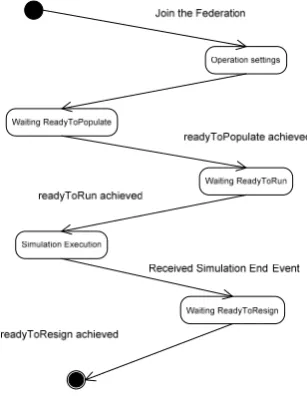
Fig. 3 illustrates the lifecycle of the component DDESOverHLAEngine, with the set of component states (rounded rectangles) and events (labels on arrows) enabling transitions (arrows) from the initial state (solid circle) to the final state (circle surrounding a solid circe).
The initialization starts with the federate joining in the federation, then proceeds with setting up the time management configuration (i.e, constrained and constraining [13]) to eventually notify the RTI about the interest in receiving and sending HLAEvent interaction objects.
Afterwards, it notifies the RTI that synchronization points readyToPopulate, first, and readyToRun, then, are
reached.
Once in the execution state, it waits for its services to be invoked by the upper or lower layer. The needed coherence between the local time and the distributed one is maintained by use of upper layer, whereas the lower layer is in charge of notifying events and time grants for the HLA service request previously submitted.
This component DDESOverHLAEngine consists of: Layer2ToLayer1 Interface
Layer1ToLayer2 Interface
RTIAmbassador
FederateAmbassador
HLA Run Time Infrastructure Engine
DIS-coordination and DIS-synchronization
logic RTI
Callback Filter
DDESOverHLAEngine
DDESOverHLAEngineAmbassador Callback
Queue
Barriers
1. A synchronization and coordination logic that
operates between the local and the distributed environment, with the mechanism to block local execution until proper HLA notifications are received through the ambassador.
2. An implementation of distributed DES (DDES)
services on top of HLA services.
For the sake of brevity no description is given of point 1. The interested reader is sent to [13] and [14] for a detailed description of synchronization and coordination aspects.
DDES service implementation
The DDES service implementation provides the following services, which are in turn based on HLA services:
- initDistributedSimulationInfrastructure()
- postProcessingDistributedSimulationInfrastructure()
- sendEvent(in event: Event)
- waitNextDistributedEvent()
- waitNextDistributedEventBeforeTime(in t: time)
The initDistributedSimulationInfrastructure() service
is implemented as follows:
initDistributedSimulationInfrastructure(): publish(HLAEventClass);
subscribe(HLAEventClass); enableTimeConstrained(); enableTimeRegulated();
registerSynchronizationPoint(readyToPopulate); registerSynchronizationPoint(readyToRun); registerSynchronizationPoint(readyToResign); synchronizationPointAchieved(readyToPopulate); wait(readyToPopulate);
synchronizationPointAchieved(readyToRun); wait(readyToRun);
where publish and subscribe statements enable the federate to send and receive HLA events, i.e., instances of the HLAEvent class that defines the HLA structure for distributed events in the DDES system, while the enableTimeConstrained and enableTime-Regulating statements enable the federate to operate in a time conservative modality by, respectively,
constraining the federate time advancement to the whole federation time as well as constraining the whole federation time advancement to the federate time.
The enableTimeConstrained and enableTime-Regulating operations are asynchronous. The above pseudo-code includes synchronizations through Barriers (see [14]) and the corresponding notification of successful processing from RTI through the ambassador component. The notifications are, respectively, timeConstrainedEnabled and timeRegulating-Enabled.
After that, the synchronization points
readyToPopulate, readyToRun and readyToResign,
which denote the states in the federate life cycle (see Fig. 3), are registered into the system by means of the registerSynchronizationPoint asynchronous statements. In analogy to the previous case, the above pseudo-code includes synchronization through Barriers and the relative notification of successful processing.
The synchronizationPointAchieved(ready-ToPopulate) statement then informs the distributed environment that the processing for the ReadyToPopulate
state has been completed and the federate is ready to pass to the next state. At this point the RTI notifies the achievement of global synchronization by use of the synchronizationPointAchieved (readyToPopu-late) statement that uses the ambassador component to unlock the wait(readyToPopulate) statement upon which the federate has been locked on.
Since there is no processing in the readyToPopulate
state, the service implementation proceeds by signalling that the federate has reached the readyToRun
synchronization point and entered in a blocking waiting for a global readyToRun signal, as for the readyToPopulate synchronization point.
The
postProcessingDistributedSimulation-Infrastructure() service is implemented as follows: postProcessingDistributedSimulation-
Infrastructure():
synchronizationPointAchieved(readyToResign); wait(readyToResign);
resignFederationExecution(
ResignAction.DELETE_OBJECTS);
This service first signals the achievement of the
readyToResign synchronization point, through the
synchronizationPointAchieved(readyToResign) statement, and then uses the wait(readyToResign) statement to wait for a global achievement of the same point.
Once the readyToResign signal is received, it proceeds
by quitting the federation through the resignFederationExecution statement and performing the resign action. This action is conventionally chosen as no HLA objects are used in the distributed simulation.
The sendEvent(in event: Event) service is implemented
as follows:
sendEvent(in event: Event):
toSend = HLAEvent.buildFrom(event);
toSend.send();
The implementation is based on the availability of the the HLAEvent component that performs the conversion between the internal event and the HLA data, and vice versa. Basing on it, the service merely consists of two HLAEvent service invocations: a first one to convert the Event object to a HLAEvent object, and a second one to send it out to the HLA environment.
The send statement is based on the homologous HLA service sendInteraction(). The service serializes local data to the HLA format according to the rules that map each HLA attribute id to a field name coded into the HLAEvent class. The serialization is carried out by converting each of the local data from their local format to an equivalent array-of-bytes format.
The waitNextDistributedEvent() service is
implemented as follows:
waitNextDistributedEvent(): do
tfuture = tcurrent + tadvancingStep; timeAdvanceRequest(tfuture);
wait(timeGrant);
while not (eventReceived); sendReceivedEventToUpperLayer();
This service consists of a do-while cycle that performs time advance requests to a future time until an event is received from the distributed system.
The future time is computed by adding the current time to the system parameter advancement step.
The timeAdvanceRequest statement is used to request a time advancement at the specified time and the wait(timeGrant) statement blocks the current process until a timeGrant RTI callback is received. While
waiting, the engine automatically processes incoming callbacks. The expected types of callbacks are of the following types:
- timeAdvanceGrant
- receivedEvent.
The timeAdvanceGrant callback is dispatched by
updating the internal clock time to the one the callback carries on.
The receivedEvent callback is dispatched by updating
the flag eventReceived to true and by storing the just-received event in a temporary buffer. According to the HLA standard, with the current time settings, an interaction received notification is always followed by a time grant notification that grants the interaction time at least.
The sendReceivedEventToUpperLayer statement follows the do-while cycle and invokes the layer 2 service schedule().
Finally, the waitNextDistributedEventBeforeTime(in t: time) service is implemented as follows:
waitNextDistributedEventBeforeTime(in t: time): do
t = tcurrent + tadvancingStep; timeAdvanceRequest(tfuture); wait(timeGrant);
while (not eventReceived) or (tcurrent<t));
if(eventReceived)
sendReceivedEventToUpperLayer();
This service behaves similarly to the
waitNextDistributedEvent() service. The only change is in
the exit condition of the do-while cycle: the sequence of time advance requests terminates once either a new event has been received or the given time has been reached.
DDESOverHLAEngineAmbassador
The component DDESOverHLAEngine implements the HLA interface FederateAmbassador in order to synchronize and manage the RTI callbacks to DDESOverHLAEngine.
The main DDESOverHLAEngine functionalities are: 1. notification of successful HLA service
processing, for example:
enableTimeConstrained, enableTimeRegulating,
etc.
2. notification of synchronization point achievement (synchronizationPointSucceed)
3. notification of time grant (timeAdvanceGrant)
4. HLA event delivery to DDESOverHLAEngine for those events that have a local recipient. All such functionalities are implemented by defining the proper statements in the respective HLA FederateAmbassador service. The implementation makes also use of:
- parallel programming primitives, like Barrier and CallbackQueue, to synchronize the DDESOverHLAEngine – DDESOverHLA-EngineAmbassador components,
- HLAEvent component to load a HLA format event in a local HLAEvent class, in order to determine whether the recipient is running in the local system or not.
This component runs in a separate thread with respect to the DDESOverHLAEngine components.
C. LAYER 2
This layer is the execution container for layer 3 components.
The interfaces to lower and upper layers are shown in Fig. 4 and 5, respectively. The Layer3ToLayer2 interface consists of two sub-interfaces: a first named
Layer3ToLayer2UserInterface, which is used by
language users, and a second named
Layer3ToLayer2DeveloperInterface used by language
developers.
The 1-to-2 interface consists of the scheduleEvent and scheduleSimulationEndEvent services. The former inserts
the generic event into the list of events, while the latter
signals that a distributed simulation end event has been
received.
Figure 5 Layer 3 to Layer 2 interface
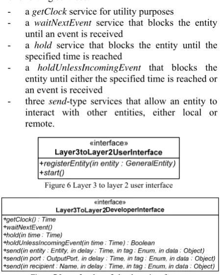
The Layer3ToLayer2UserInterface is shown in Fig. 6.
It provides services to configure and manage the system. It consists of a registerEntity service to configure which
entities will be running in the simulator and a startEngine
service to start the components.
The Layer3ToLayer2DeveloperInterface is shown in
Fig. 7. It provides services to define entities and consists of the following services:
- a getClock service for utility purposes
- a waitNextEvent service that blocks the entity
until an event is received
- a hold service that blocks the entity until the
specified time is reached
- a holdUnlessIncomingEvent that blocks the
entity until either the specified time is reached or an event is received
- three send-type services that allow an entity to
interact with other entities, either local or remote.
Figure 6 Layer 3 to layer 2 user interface
Figure 7 Layer 3 to layer 2 developer interface
C.1 Implementation
This implementation includes the following components:
- Engine: coordinates the execution of the
simulation components implemented at layer 3 - Entity: provides a layer 2 reference to layer 3
entities
- Event: provides a mechanism to implement
coordination among entities.
Engine
The simulation engine is responsible for the simulation initialization and execution according to the PI paradigm. The hierarchy that introduces simulation engines for local execution and engines for distributed execution is already discussed in [15].
Local Simulation Engine
This engine introduces the basic support for the PI paradigm.
It provides the implementation of services send, wait
and hold through the scheduling of specific type of
events, below described; and a set of synchronization
primitives to manage the execution of the entities (i.e., the logical processes in the PI paradigm).
The engine’s core method is the start method, which is implemented as follows:
start():
isRunning = true; startAllEntities();
while (isRunning) {
for each LocalEntity e { if (e.isRunnable()) {
e.restart();
setOneEntityInRunState(); }
}
if (eventList.size() > 0) { getNextEvent().process();
} else {
isRunning = false; }
}
First, the flag that denotes the engine running is set. Then all entities are started through the Thread’s method start [14].The entities then are blocked while waiting for the engine to allow them to run.
At this point the engine enters the processing cycle that is composed of two blocks: the first in which all the runnable entities are activated (they compete to be run by the engine); and the second in which either the next event is processed, if present, or the simulation end condition is determined, if there are no future events.
Distributed simulation engine
The distributed engine extends the local engine by redefining the start method and by implementing event scheduling services for remote recipients.
The start method is redefined as follows:
start():
ddes.initDistributedSimulationInfrastructure() isRunning = true;
startAllEntities();
while (isRunning) {
for each LocalEntity e { if (e.isRunnable()) {
e.restart();
setOneEntityInRunState(); }
}
if (eventsList().size() > 0) {
Time nextEventT=seeNextEvent().getTime(); ddes.waitNextDistributedEventBeforeTime (nextEventTime);
} else {
ddes.waitNextDistributedEvent(); }
getNextEvent().process(); }
ddes.postProcessDistributedSimulation- Infrastructure();
In the else block, the simulation condition can not be inferred only from the empty status of the local event list, since of the presence of other remote simulators.
The schedule service introduces a test to find out whether the recipient is local or remote. If it is local the LocalEngine service is invoked, otherwise the layer 1 send event is invoked on the given event.
This engine also implements the Layer1ToLayer2 services scheduleEvent and scheduleSimulationEndEvent.
The former is implemented by scheduling a local
PDistributedToLocalEvent (see further on) version for
the received Event. The latter is simply implemented by
scheduling an internal layer 2 SimulationEndEvent at the
specified time.
Entity
SimJEntity is the layer 2 component that encapsulates the layer 3 logic process.
The entities are structured as shown in Fig. 8.
Figure 8 SimJ Entity Class Diagram
The interface SimJEntity is only in charge of marking the interface for layer 2 entities. SimjEntity is implemented by LocalEntity and RemoteEntity components.
The LocalEntity component implements the services provided to layer 3 developers. It plays an intermediary role between layer 3 logical processes, which invoke layer 3 to layer 2 services, and the engine, which actually implements the send, wait, etc., services.
The life cycle of the LocalEntity component evolves among four states, as shown in Fig. 9:
1. RUNNING: state in which the component performs layer 3 component’s logic
2. HOLD: state in which the component sleeps for a given time
3. WAITING: state in which the components sleeps until an event is received
4. HOLD_UNLESS_INCOMING_EVENT: state in which the component sleeps until either a given time has passed or an event is received. The Engine – LocalEntity synchronization is achieved through two semaphores: OneEntityIn and RighToRun
defined in the Engine and LocalEntity components, respectively.
OneEntityIn guarantees that only one entity at time, and thus logical process, is running in the engine. The
execution of one entity at time is needed to ensure simulation reproducibility.
RightToRun is the semaphore that the wait-like service requests use to block the LocalEntity while waiting for the proper event to be processed.
RemoteEntity is the layer 2 component used to refer to an entity running on a remote system. It does not play any active role.
Figure 9 LocalEntity State Diagram
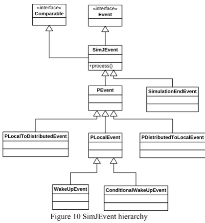
Events
Events are organized according to the component hierarchy shown in Fig. 10.
«interface»
Event
PEvent
PLocalEvent
PLocalToDistributedEvent PDistributedToLocalEvent
SimulationEndEvent
WakeUpEvent ConditionalWakeUpEvent
+process()
SimJEvent
«interface»
Comparable
Figure 10 SimJEvent hierarchy
The base component SimjEvent introduces the abstract operation process(), which embodies the action
to be taken when the respective event class is processed. The abstract component PEvent introduces the events for the PI simulation paradigm. PLocalEvent defines the base notification event for the PI paradigm in a local environment. Special PI local events (e.g. WakeUpEvent and ConditionalWakeUpEvent) are defined by specializing the component PLocalEvent and by overriding the process method, and similarly for remote recipient and remote sender PI events.
The definition of the process() operation is defined in
the following subsections, one for each class of event. PLocalEvent
This event is scheduled when a local entity sends a message to another local entity.
pass from the WAITING state to the RUNNING state, and deliver it.
The action also checks whether the recipient is waiting for an event. If not, the above action is ignored. No deferred event list is currently available in this layer 2 implementation.
WakeUpEvent
This event is scheduled when a local entity invokes the
hold() operation. The action taken when this event is
processed is: send a signal to the associated entity in order to make it pass from the HOLD state to the RUNNING state.
ConditionalWakeUpEvent
This even is scheduled when the entity invokes the
holdUnlessIncomingEvent() operation.
The actions taken when this event is processed are: check whether the entity has already received an event and, if not, send a signal to the entity in order to make it pass from the WAITING state to the RUNNING state and deliver the event itself.
The check makes use of information related to the request ordinal number and the current entity state in order to determine whether an event has already been delivered to the entity.
SimulationEndEvent
Since this event is shared by all discrete event simulation paradigms, it is defined straight from the base interface SimJEvent.
The processing of this event is to stop the engine by use of the homonym engine service.
PLocalToDistributedEvent
This event represents local sender to remote recipient events. When scheduled it is immediately processed in order to optimize the execution of the distributed simulation. Its processing involves the invocation of lower level services to send it out to the distributed environment, which is in charge of delivering it.
PDistributedToLocalEvent
This event is scheduled when a distributed event for a local recipient is received by the lower layer.
The action taken when this event is processed is the same as for PLocalEvent. What changes between the two classes is that the remote sender can not be directly referenced.
D. Layer 3
The purpose of this layer is to provide the domain dependent components that implement the layer 4 language.
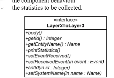
Layer 3 offers a domain-independent interface to layer 2 to make its components available for the layer 2 synchronization procedures (see Fig. 11).
The interface is composed of eight services, among which the following four services are of primary interest:
- body: to encode the component behaviour, i.e.
the sequence of state updates and layer 2 service calls
- printStatistics: to print the private statistics
collected throughout the simulation
- setEventReceived: to inform that an event has
been received
- setRecevedEvent: to pass the just-received event.
The system is provided with a facility component that implements the basic operations to allow interaction with layer 2. This component can be specialized to implement custom logic or can be replaced in case of different layer 3 implementations.
According to the autonomous component paradigm, the design of custom components includes decisions related to:
- the number of input and output ports
- the type of events to be sent and received on each port
- the component behaviour - the statistics to be collected.
Figure. 11 Layer 2 to layer 3 interface
D.1 Implementation
An implementation is provided for the specific domain of interest, i.e., EQN simulation.
The simulation components are designed to exploit component reusability by using all state-of-art Java and object-oriented techniques. In particular, the following design guidelines have been adopted:
- decoupling functionalities by introducing flexible parameter configuration for those parameters that do not affect the component behavior (e.g., decision policies like FIFO, etc.) - using inheritance for those parameters that affect
component behavior (e.g., preemption, etc.). The simulation component groups are: the typical EQN component (users, waiting systems, service centers, routers and special nodes), a set of support components and a policy modeling framework.
The policy modeling framework is a general framework within which every policy has to be implemented. The framework is based on a generic hierarchy that includes parameters such as:
- the decision data type,
- the decision object type (aka explicit input), - the implicit input type,
- the state type.
The hierarchy introduces a classification of policies, for example: input dependent policy, state dependent policy, implicit input dependent policy and so on.
The design of a new policy is thus carried out by defining the parameter type of the policy and the policy class it fits best.
The following subsections illustrate some of the jEQN components in terms of: purpose, ports, behaviour and parameters.
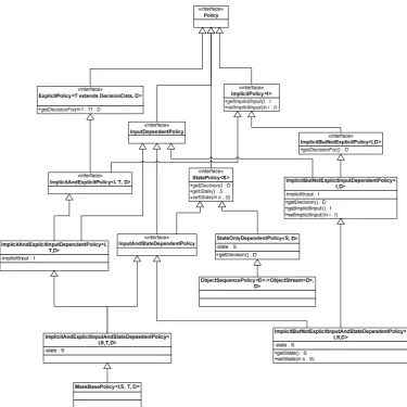
Policy Modelling Framework
jEQN policies are defined according to the meta-model shown in Fig. 12.
The model considers four parameters for each of the factors that affects the policy decision, namely:
• T, for the type of explicit input
• I, for the type of implicit input
• S, for the type of internal state
• D, for the type of decision expected.
The policies are defined, and their relationships established, as a function of the parameter combination (T, I, or S) they use. Thus, we have a policy that only depends from the explicit input T, one that depends on the implicit and explicit input (T and I), and so on.
A MaskBasePolicy is introduced as a full parameterized policy in order to provide a common reference for jEQN components.
The design of a new jEQN policy involves two basic steps: identify the meta-class and define the parameter’s type.
The policy can thus be implemented by properly allocating the meta-class and then defining the decision method.
Source
The purpose of this group of components is to generate and insert new users into the system.
The port of Source components is an output port through which users flow.
The behaviour is as follows:
1. check whether the termination condition has been reached or not
2. if not, wait for the inter-arrival time
3. generate a new user and send it through the output port
The base component can be parameterized by specifying proper implementation of:
- inter-arrival time sequence - termination policy
- user generator.
Routers
The purpose of this group of components is to route users towards specific entities or ports.
Currently, this group holds the component Router only.
The ports of a Router component are: - an input port to receive users - a set of output ports to forward users The behaviour is as follows:
1. wait for the next user to come in 2. decide on which port to forward it 3. send it out through that port 4. go back to step 1.
The Router component has a single parameter, i.e., the routing policy
Waiting Systems
The purpose of this group of components is to store users that can not be immediately processed by the service center.
The simulation components in this group are two: PreemptiveWaitingSystem and NonPreemptive-WaitingSystem.
The behavior of the component NonPreemptiveWaitingSystem is as follows:
1. wait for an event
2. if it is an incoming user, insert it in the waiting system
3. if it is a request for the next user to be processed, then:
a. if the waiting system is not empty, extract the next user and send it,
b. else, wait for a new user to come in and then send it to the service center.
The behavior of the component PreemptiveWaitingSystem is as follows:
1. wait for an event
2. if it is an incoming user, assess whether it has the right of preempt or not:
a. if so, send it to the service center, b. else, insert it in the waiting system 3. if it is a next user request, then:
a. if the waiting system is not empty, extract the next user,
b. else, wait for a new user to come in and then send it to the service center. The ports of the component NonPreemptive-WaitingSystems are:
- an input port for the incoming user - an output port for the user to be processed - an input port for the request of a new user
The ports of the component PreemptiveWaiting-System are:
- an input port for the incoming user - an output port for the user to be processed - an input port for the partially-processed users
The parameters of the component NonPreemptiveWaitingSystem are:
- a UserQueue (data structure) where to store users,
- a user service request generator, in order to allow the implementation of service-based queuing policies.
The parameters of the component PreemptiveWaitingSystem are the same of the non preemptive one with the addiction of:
- preemption policy.
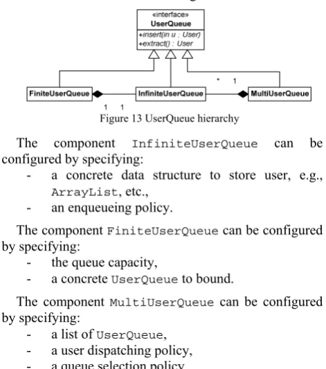
The UserQueue is an abstract component that offers user insertion and extraction methods. It is specialized into FiniteUserQueue, InfiniteUserQueue and MultiUserQueue as shown in Fig. 13.
Figure 13 UserQueue hierarchy
The component InfiniteUserQueue can be configured by specifying:
- a concrete data structure to store user, e.g., ArrayList, etc.,
- an enqueueing policy.
The component FiniteUserQueue can be configured by specifying:
- the queue capacity,
- a concrete UserQueue to bound.
The component MultiUserQueue can be configured by specifying:
- a list of UserQueue, - a user dispatching policy, - a queue selection policy.
Service Centers
The purpose of this group of components is to simulate the user processing. The components in this group are: NonPreemptiveServiceCenter, Preemptive-ServiceCenter and InfiniteServer.
The behavior of the component NonPreemptiveServiceCenter is as follows:
1. request the next user to process 2. wait for the next user
3. process user request 4. go back to step 1.
The behavior of the component PreemptiveServiceCenter is as follows:
2. wait for the next user, 3. process user request,
4. if interrupted, then send partially-processed user back to the waiting system, then go back step 3, 5. else, go back step 1,
6. go back to step 1.
The behavior of the component InfiniteServer is as follows:
1. wait for the next user to process,
2. forward it to the next entity at a delayed time as much as the service request time,
3. go back step 1.
The ports of the component NonPreemptive-ServiceCenter are:
- an input port for the users to be processed, - an output port for the processed users,
- an input port to request the users to be processed.
The ports of the component Preemptive-ServiceCenter are:
- an input port for the users to be processed, - an output port for the processed users, - an output port to re-enqueue interrupted users The ports of the component InfiniteServer are:
- an input one for the users to be processed, - an output one for the processed users.
The components of this group do not have parameters.
E. Layer 4
The jEQN language provides a restricted set of architecture services for building and configuring EQN simulation programs, and a set of domain-specific primitives.
The services define the Layer4ToLayer3Interface, i.e. Layer3ToLayer2UserInterface above introduced.
The primitives are identified by layer 3 EQN components. Interested readers are sent to [1] for an example use of jEQN.
IV. CONCLUSIONS
This paper has illustrated jEQN, a Java-based language that significantly reduces the extra effort needed to develop distributed simulators of extended queueing networks (EQNs). jEQN enables simulator developers to build distributed simulators as they were to be locally executed.
The language is based on a four-layered architecture whose services and data interfaces between the layers have been accurately described in this paper.
The implementation details of each layer have been presented in terms of service interface implementation, main components and relationships with the upper and lower layers, when appropriate.
The paper points out how the system takes into account the interaction with the distributed environment both within layer 1 (HLA) and within layer 2.
A very schematic presentation has also been given for jEQN components at layer 3 and the language at layer 4.
ACKNOWLEDGMENT
The authors would like to express their sincere thanks to Prof. G. Iazeolla for his insightful contribution.
REFERENCES
[1] A. D'Ambrogio, D. Gianni and G. Iazeolla, “jEQN: a Java-based Language for the Distributed Simulation of Queueing Networks”, LNCS vol. 4263/2006, Proceedings of the 21st International Symposium on Computer and Information Sciences (ISCIS'06), Istanbul, Turkey, Nov,
2006.
[2] R. Fujimoto, Parallel and Distributed Simulation Systems, Wiley (2000).
[3] G. Bolch, S. Greiner, H. de Meer and K. Trivedi, Queueing Networks and Markov Chains, Wiley (1998).
[4] M. Veran and D. Portier, “QNAP2: A Portable Environment for Queueing Systems Modelling”, Raport de Recherche 314, INRIA, Jun, 1984.
[5] C. Sauer, E. MacNair and S. Salza, A Language for Extended Queuing Network Models, IBM Journal of Research and Development, Vol. 24, n. 6, Nov, 1980.
[6] IEEE, Standard for Distributed Interactive Simulation - Application protocols, Technical Report 1278.1A, IEEE (1998).
[7] IEEE, Standard for Modeling and Simulation (M&S) High Level Architecture (HLA) – framework and rules, Technical Report 1516, IEEE (2000).
[8] G. Riley, M. Ammar, R. Fujimoto, A. Park, K. Perumalla and D. Xu, “A Federated Approach to Distributed Network Simulation”, ACM Transaction on Modeling and Computer Simulation (TOMACS), Vol. 14, n. 2, Apr, 2004.
[9] E. Page, R. Moose and S. Griffin, “Web-based Simulation in SimJava using Remote Method Invocation”,
Proceedings of the 1997 Winter Simulation Conference,
Atlanta, GA, Dec, 1997.
[10]P. Jacobs, N. Lang and A. Verbraeck, “D-SOL: A Distributed Java Based Discrete Event Simulation Architecture”, Proceedings of the 2002 Winter Simulation Conference, San Diego, CA, Dec, 2002.
[11]K. Perumalla, “μsik: A Micro-kernel for Parallel/Distributed Simulation Systems”, Proceedings of the 19th Workshop on Parallel and Distributed Simulation (PADS’05), Monterey, CA, Jun, 2005.
[12]R. Nance, “The time and state relationships in simulation modeling”, Communications of the ACM, Vol. 24 n. 4, Apr, 1981.
[13]F. Kuhl, R. Weatherly and J. Dahmann, Creating Computer Simulation Systems: An Introduction to the High Level Architecture, Prentice Hall (1999).
[14]D. Lea, Concurrent Programming in JavaTM: Design Principles and Pattern, 2nd Edition, Prentice Hall (2000). [15]A. D'Ambrogio, D. Gianni and G. Iazeolla, “SimJ: A
Framework to Develop Distributed Simulators”,
Proceedings of the 2006 Summer Computer Simulation Conference, Calgary, Canada, Aug, 2006.
D. Gianni is a PhD candidate in Computer Engineering at the University of Rome TorVergata, Italy. His research interests are on distributed simulation, distributed systems, software reusability and interoperability.