(UDC: 621.186:004.4)
Thermo-mechanical coupling procedure using partitioned approach -
Application to arc welding simulation
V. Dunić1, N. Busarac1, D. Rakić1, V. Slavković1, R. Slavković1*, M. Živković1
1
Faculty of Engineering Kragujevac, University of Kragujevac, Serbia [email protected]
*Corresponding author
Abstract
This study considers using of Component Template Library (CTL) as middle-ware and weak coupling algorithm of software components for heat transfer and structure analysis. The CTL interface is specially designed to exchange data between the software components. The structure simulation component is linked to the heat transfer simulation component by remote method invocation and by dynamic linkage. The simulation of welding procedure with the moving heat source was used to describe how the proposed procedure works. The heat transfer component computes changes of temperature at all nodes for given values of heat source and the structure analysis component computes the strains induced by the temperature changes in each time step. The CTL interface provides transfer of data between communication points into the component codes. The requirements for the simulation interface and software architecture are given and analyzed. Using the CTL as middle-ware, the coupling of software components in partitioned formulation becomes satisfying solution for such simulations.
Keywords: thermo-mechanical coupling, Component Template Library (CTL), heat transfer, arc welding, finite element method
1. Introduction
Heat transfer and structural engineering problems can be solved using finite element method (FEM) software, independently. Thermal changes induce appearance of thermal strains and mechanical changes induce appearance of thermal energy. Need to exchange the data between independent software components is arising for many scientific areas of research. Thermo-mechanical coupled FEM software is useful tool for analysis of scientifically and technologically interesting problems. Many advanced material models (e.g. shape memory alloys) need thermo-mechanical interaction for accurate simulation of behavior.
C et al. (2001), computational simulation of systems, with a structure as a major component, was decomposed into partitions. Coupled system terminology, and possible scenarios and approaches of partitioning were considered. Details about potential use of partitioned analysis procedures for the analysis of coupled dynamical systems were presented. The application of service oriented architectures (SOA) in finite element analysis was examined by Mackie R. (2012). Such services can reside on the same computer or on distributed computers. For the examined case, the client sent data about structural model to the service, which used this data to construct the finite element model. The finite element calculations were executed on the finite element model and the client accessed those results using SOA approach. For the design of offshore wind turbines in Srisupattarawanit T et al. (2006), software components were coupled via the Component Template Library (CTL) [Niekamp R (2005)]. The incident wave field was given by a stochastic wave process far from the structure. The effect of the interacting flexible structure was included via a coupling computation. The chosen software architecture allowed a modular coupling concept. As a numerical example, an offshore wind turbine was simulated, which has an additional fluid interaction with the stochastic wind field.
An efficient way to simulate multi-physics scenarios is the partitioned coupling approach [Matthies HG et al. (2006), Felippa C et al. (2001), Gatzhammer B et al. (2010)]. Software established for single field analysis combined with some coupling environment provides a multi-physics simulation tool. All previous authors developed and analyzed fluid-structure interaction algorithms using partitioned approach. Thermo-mechanical problems could be solved in that way, too. One of FSI coupling algorithms suggested in [Matthies HG et al. (2006)] is modified and adapted for solution of thermo-mechanical problem in this paper. The CTL [Niekamp R (2005)] interface is used as middle-ware for coupling of heat transfer and structure analysis component. It provides transfer of data between communication points into the module codes. Simulation of welding procedure with moving heat source was used to describe how the proposed procedure works. The heat transfer component computes change of temperature at all nodes for given values of heat source and the structure analysis component computes strains induced by temperature change in each time step for the computed temperatures.
2. Methods
The heat transfer analysis component of PAK software (PAKT) [Kojiš M et al. (2011)] defines procedure for solving the problem of heat conduction through solid environment using FEM. Differential equations of energy balance is based on fundamental principle of energy conservation [Kojiš M et al. (1998), Živkoviš M (2006), Živkoviš M et al. (2010)].
The structure analysis component of PAK software (PAKS) [Kojiš M et al. (2011)] defines procedure for linear and non-linear structural analysis. The original methodology based on the books [Kojiš M et al. (1998), Živkoviš M (2006)] of the program authors is implemented, among others in the field of thermo-elasticity and thermo-plasticity. Because of the simplicity, it is assumed linear thermo-elastic isotropic constitutive model for the example presented in this paper.
Until now, those two software components have been used separate for the solution of problems. PAKT has calculated temperatures at each node for all time steps. The results have been written into the file ZITEMP (Figure 1). PAKS has read the temperature data and calculated stresses and strains afterwards (Figure 2).
Wissenschaftliches Rechnen, TU Braunschweig, Germany and has been widely used for the partitioned coupling algorithms application. The CTL is based on C++ generic template programming. Interface and implementation are connected throw a communication channel, e.g. TCP/IP or Message Passing Interface (MPI), so a component is independent of location. The main focus of CTL is to transform existing C/C++ or FORTRAN libraries to remote accessible software components. The CTL can be used and implemented by C, FORTRAN, or C++ codes. The CTL uses the C-preprocessor for the code generation which handles all needed communications [Matthies HG et al. (2006), Niekamp R (2005)]. The syntax of this interface uses #define and #include directives.
Fig. 1. The PAKT calculates the temperature field and writes it into the file
Fig. 2. The PAKS read the temperatures and calculates stresses and strains
To couple PAKS and PAKT software components for this purpose, the new class paktci is defined as:
#define CTLClass paktci
#include CTLClassBegin
#define CTLConstructor1 (const int8, const string), 2
#define CTLMethod1 void, datasend, (const int8,array <double>), 2
#define CTLMethod2 void, solve, (array <double>), 1
#include CTLClassEnd
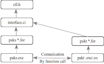
The dependencies on the bottom level (Figure 4) are obtained by compilation and linkage of the upper dependencies Matthies HG et al. (2006). There are two main parts: the heat transfer simulation component PAKT and the structure simulation component PAKS. All dependencies of these two components are located in the interface header interface.ci. The solver component
paks.exe is linked to the simulation components by remote method using the pakt.exe or by dynamic linkage using the pakt.so.
Fig. 4. Source dependencies of the thermo-mechanical condition coupled architecture
The client is PAKS component and C++ code which defines client class necessary for communication is given below:
#define CTL_ClientTM
#define CTL_ClassPrefix paktci
#include <../ci/pakt.ci>
The service which client uses is the PAKT component and C++ code which defines service class is given below:
define CTL_ConnectTM
define CTL_ClassPrefix paktci
include <../ci/pakt.ci>
void CTL_connect()
{ctl::connectTM<paktci, ctl::Extern::paktci>();}
1.1 Coupling algorithm
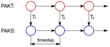
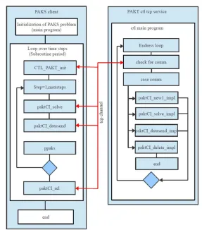
The thermo-mechanical coupling algorithm using the CTL interface is presented in Figure 5. The PAKS component is initialized as a client application. Using the CTL_PAKT_init
subroutine, the CTL PAKT component is initialized as service by paktCI_new1_impl
subroutine into the period loop of PAKS component. The CTL_PAKT_init subroutine is given below:
subroutine CTL_PAKT_init(gime,simu_handle,dimvec) integer*8 dimvec,dimstring,simu_handle
exect='../pakt1/PakTService.exe -l tcp -f "./logfile" stderr:a\0' simu_handle = -1
dimdt=100 dimstring=20
call paktCI_new1(exect, dimvec, dimstring, gime, simu_handle) if (simu_handle .eq. 0 ) then
write(*,*) ' could not create simu_handle pakt new1' endif
return end
Fig. 5. The coupling algorithm of thermo-mechanical coupling of PAK software components
The paktCI_new1_impl subroutine is invoked just once, and it's used for initializing of CTL component PAKT. Linkage is given by definition of location of PAKT service exect as TCP. The paktCI_new1_impl subroutine is given below:
subroutine paktCI_new1_impl(np,dimime,gime) use temperatures
implicit double precision(A-H,O-Z) include 'paktcommon'
character*20 gime init=0
call PAKT(gime,init) np=nodesnumberT end
After the PAKT component is initialized, we have loop over time steps. The service subroutines, paktCI_solve_impl and paktCI_datasend_impl are called to solve temperatures and to send calculated temperatures to client. Subroutine paktCI_solve_impl solves temperatures in each of "nsteps" number of steps. Subroutine PAKT is the main subroutine of heat transfer component. Subroutine paktCI_solve_impl is given below:
subroutine paktCI_solve_impl(nsteps) include 'paktcommon'
common /filenameT/ gime integer*8 nsteps
call PAKT(gime,nsteps) end
Subroutine paktCI_datasend_impl is used to send calculated temperatures to client and is given below:
subroutine paktCI_datasend_impl(givestep,dimtemp,temppaks) use temperatures
integer*8 dimtemp,givestep
double precision temppaks(dimtemp),ctltime include 'paktcommon'
do i=1, nodesnumberT
temppaks(i)=temperature(i+givestep*nodesnumberT) enddo
return end
At the end, subroutine paktCI_delete_impl is used to execute some code before the de-initializing PAKT service.
subroutine paktCI_delete_impl() use temperatures
if(allocated(temperature)) deallocate(temperature) return
end
1.2 Numerical example test
The coupling algorithm (Figure 5), developed for thermo-mechanical problems, was verified on the example of arc welding process.
The finite element model has 20160 solid elements with 25476 nodes. The thermo-elastic material constants are: Young modulus E2.1 10 11N m/ 2, Poisson‘s ratio
0.33 and coefficient of thermal expansion
12.6 10 6 0C1 regardless change of the temperature. The environmental temperature is 200C. The dependence of thermal conductivity k on temperature is given in Table 1.T 0
C 20 350 700 1700
k
0
W m C
36 38 35 35
Tab. 1. Coefficients of thermal conduction
Heat is conveyed to the sheet metal material according to the Gauss distribution:
2
2 2
kr m
q q e , (1)
where: q2m is flux at point r0, k3 is material constant and r is radius of heat effects.
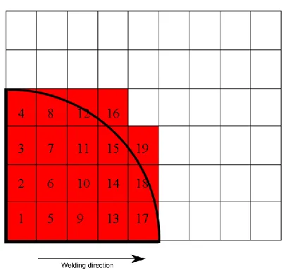
For the realization of this problem, it is necessary to make a particular algorithm which would provide the given distribution of flux per elements faces. The heat quantity conveyed from electric arc must be distributed per surface of elements in radiusr10mm. The motion speed of electrode tip is given, so, it was necessary to make FEM model which satisfy:
w
x v t
, (2)
where x is the element dimension in the welding direction, vw is speed of heat source motion, and t is time increment. It was found that heat conveys through five elements in the motion directions, and four elements in the direction orthogonal to the plate symmetry (Figure 6). So, 192x4 distribution functions are defined (192 elements in the welding direction and 4 elements in the orthogonal direction).
Average value of heat quantity for each heat affected element was calculated as:
2
e A
Q
q dA, (3)e A
A
dA, (4)avg e e e Q q A
, (5)
Fig. 6. Elements loaded by heat flux
Welding speed is 0.208 10 2m s, welding energy is q1150800J m and the whole
structure is heated before the welding to reach temperature 1800C.
3. Results and discussion
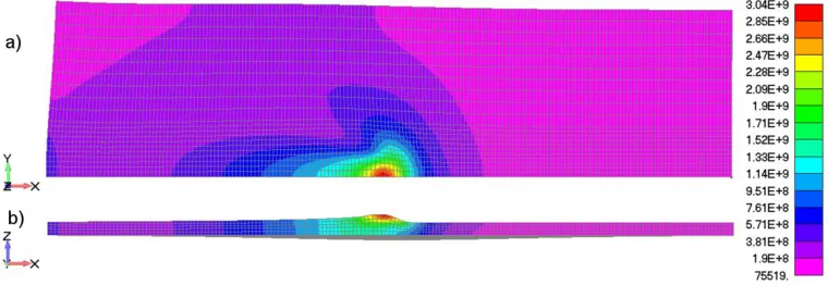
After the thermo-mechanical analysis using the coupled PAKS and PAKT components was done, the obtained results are presented in Figures 7 and 8. The heat transfer and thermo-elastic analysis was done in 192 time steps. In Figure 7, change of temperature field during the welding process is given. That change induces occurrence of the thermal strains and stresses at the welding place (Figure 8).
Fig. 7. Temperature field in the 96st step: a) XY plane b) ZX plane
The arc welding simulation problem, presented in this paper described need for coupling of already existing software components. The results obtained by this computations, provide possibility to correct welding parameters and set desired properties of welding zone (heat affected zone thickness and temperature of any point during the welding and after the end of process).
Fig. 8. Stress field in the 96st step - Deformed configuration (Scale:5): a) XY plane b) ZX plane
Further research should be directed to the two ways coupling by this approach. Possible plastic or phase transformation strains occurrence can induce dissipation of energy and change of temperatures. Such coupled problems are wide in many areas, so it will be important to implement same strategy for similar material models (phase transformation models, shape memory models etc.).
4. Conclusions
communication between the codes. The remote communication possibility has advantage because the computation can be carried out on a remote computer Mackie R. (2012). Also, there is possibility of code parallelization because CTL uses MPI.
CTL is a template library and in its simplest configuration it depends on nothing than the standard libraries which are available on nearly all UNIX platforms. The CTL can be used for fast prototyping of distributed software system. The idea behind the CTL is to provide a mechanism which makes the development of distributed systems as easy as possible, so that the differences between traditional monolithic programs and complex distributed software systems nearly vanish [Niekamp R (2005)].
We have demonstrated this coupling method on a thermo-mechanical dependency. The arc welding process simulation was used to describe possible application of such coupling algorithm in case of thermo-elastic material model. Proper welding simulation is important because of possible cracks and impermissible deformations, induced by temperature changes.
Извод
Процедура за термо-механичко спрезање коришћењем
партиционисаног приступа – Примена у симулацији лучног
заваривања
В. Дунић1, Н. Бусарац1, Д. Ракић1, В. Славковић1, Р. Славковић1*, М. Живковић1
1Факултет инжењерских наука, Универзитет у Крагујевцу, Србија [email protected]
Резиме
Овај рад разматра коришћење Component Template Library (CTL) у функцији мидлвера и алгоритма за слабо спрезање софтверских компоненти за структурну анализу и проводјење топлоте. CTL интерфејс је специјално прилагодјен размени података медју софтверским компонентама. Компонента структурне симулације је повезана са компонентом за проводјење топлоте методом даљинског позивања и динамичким линковањем. При описивању рада ове процедуре коришћена је симулација поступка заваривања са покретним извором топлоте. Компонента за проводјење топлоте израчунава промену температуре у свим чворовима за задате вредности извора топлоте док компонента структурне анализе израчунава деформације настале променом температуре у сваком временском кораку. Размена података измедју комуникационих тачака унутар кода сваке од компонената омогућена је коришћењем CTL интерфејса. У раду су анализирани и захтеви симулационог интерфејса и софтверске архитектуре. Коришћење CTL-a у спрезању софтверских компоненти при партиционисаној формулацији показује се као задовољавајуће решење у симулацији оваквих проблема.
Кључне речи: термо-механичко спрезање, Component Template Library (CTL), проводјење топлоте, лучно заваривање, метод коначних елемената
References
Felippa C, Park K, Farhat C (2001). Partitioned analysis of coupled mechanical systems.
Computer Methods in Applied Mechanics and Engineering 2001;190(24-25):3247–70. Gatzhammer B, Mehl M, Neckel T (2010). A coupling environment for partitioned
multiphysics simulations applied to fluid-structure interaction scenarios. Procedia Computer Science 2010;1(1):681–9.
Kojiš M, Slavkoviš R, Živkoviš M, Grujoviš N (1998). Finite element method – Linear analysis. Kragujevac: Faculty of Mechanical Engineering, University of Kragujevac; 1998. Serbian.
Mackie R. (2012) Application of service oriented architecture to finite element analysis.
Advances in Engineering Software 2012;52(0):72–80.
Matthies HG, Niekamp R, Steindorf J (2006). Algorithms for strong coupling procedures.
Computer Methods in Applied Mechanics and Engineering 2006; 195(17-18):2028–49. Niekamp R (2005). CTL Manual for Linux/Unix for the Usage with C++. Institut fur
Wissenschaftliches Rechnen - TU Braunschweig; Germany; 2005.
Srisupattarawanit T, Niekamp R, Matthies HG (2006). Simulation of nonlinear random finite depth waves coupled with an elastic structure. Computer Methods in Applied Mechanics and Engineering 2006;195(23-24):3072–86.
Živkoviš M (2006). Nonlinear analysis of structures. Kragujevac: Faculty of Mechanical Engineering, University of Kragujevac; 2006. Serbian.
Živkoviš M, Nikoliš A, Slavkoviš R, Živiš F (2010). Non-linear transient heat conduction analysis of insulation wall of tank for transportation of liquid aluminum. Thermal Science