The Manufacturing, Optimization and Upgrading
of Cable Clutch System of Cars with the Goal of
Smoothing Clutch Pedal of Motor Vehicles
Asghar Mohseni, Bahman Mohammad Hossein Rahmati, Nosrat Sahrai
Sama Technical and Vocational Institute, Islamic Azad University of Bonab, Iran.
ABSTRACT: To prevent the nail-like jam between clutch bearing and clutch plug or to inhibit such a jam in gearbox funnel during the assembly of bearing on the clutch plug while the clutch is working, a little looseness (e.g. 1-2 mm) is permitted between them, but such a gap causes a small release in clutch pedal. Therefore, the present study aims to eliminate this gap and to reduce the clutch release which enables modification in size of clutch system level. From theoretical viewpoint, the present study shows that the modification of the size of clutch system lever may significantly reduce up to 30% of applied for on clutch pedal. In this regard, all modification steps of clutch system are practically in Pride (Kia®) and the obtained clutch smoothing is significant. Keywords: clutch bearing, nail-like looseness, bearing and clutch plug, short arm length of small pedal, permanent magnet.
INTRODUCTION
Clutch is a device for real-time transmission of power, speed and torque to gearbox. Using this device, one could connect or disconnect the connection between motor and gearbox. In a single-plate mechanical gearbox, there is a mill-like piece at the central part of solar spring that contacts with clutch bearing. When a force is applied on clutch plug and bearing, the mill-like piece is directed inward and comes close to the middle part of the spring of the clutch plate. In this moment, the spring swirls in a unidirectional manner on its support points, and its surrounding part move away from clutch plate to release it. To prevent the nail-like jam between clutch bearing and clutch plug or to inhibit such a jam in gearbox funnel during the assembly of bearing in the clutch plug while the clutch is working, a little looseness (e.g. 1-2 mm) is permitted between t them, but such a gap causes a small release in clutch pedal and as a result the pedal moves 2-5 cm away from its initial course without involvement in transmitting the force to the mill-like piece. To understand this better, the concepts of gap or release in the following titles should be dealt with in detail.
Distance or Looseness between Bearing Nail and Clutch Plug
To get the clutch bearing fixed in clutch plug, a small looseness between bearing nails and clutch plug is added by the manufacturer because if this looseness is not designed, the clutch plug does not easily get on the clutch bearing nail when the bearing is placed on gearbox funnel. Therefore, a 2 mm looseness between clutch plug and bearing nail of the clutch is added (Figure 1).
107 Distance or Looseness between Clutch Bearing and Mill-Like Piece
To prevent the contact between clutch bearing and mill-like piece while the clutch is working, small looseness (3 mm) is added. The existence of this looseness leads to short release of the pedal in its 2-5cm of initial course without involvement or imposing force on mill-like device (Figure 2; Mohammadi Bosar, 1994).
Figure 2. Looseness between clutch bearing and clutch disc
Permissible Axial Looseness of Crankshaft
The minimum longitudinal looseness between crankshaft and bearings or between crankshaft and connecting rods should be imposed in the distance between the thrust washer and crankshaft so as to make the thrust washer the only guarantee of axial movement of the crankshaft. Therefore, at the time of measuring the axial looseness of crankshaft, a screw driver should be placed between one of the main bearing caps and crankshaft counterweight so as to direct the crankshaft forward. Then, the extent of looseness between crankshaft and thrust washer is controlled by a filler. The permissible value of looseness is almost between 0.08 to 0.2 mm as shown in Figure 3 (Mohammadi Bosari, 1995).
Figure 3. Measurement of axial looseness of crankshaft
108 and probability of their failure. This prediction is possible based on computer analysis and examination of previously obtained experimental data. Despite the studies on different parts of clutch by above-mentioned authors, research concerning the following issues have not yet been conducted on clutch system and it is for the first time that these studies are theoretically and practically done.
1- Examination and determination of distance between clutch bearing nail and clutch plug 2- Looseness between bearing and disk thumb
3- Looseness of longitudinal or axial movement of crankshaft
Therefore, it is necessary to conduct a study in this regard. The present study aims to correct the distance between clutch bearing nail and clutch plug so to:
1- Improve the performance of clutch system in a motor vehicle. 2- Minimize the distance between bearing nail and clutch plug
MATERIALS AND METHODS
In the present study, the performance of a normal clutch system plug in a Pride Car was evaluated by a filler. To evaluate the performance of the clutch system, this ability was used. Considering the fact that the structure of nail part of bearing should be designed in a way in which the partial distance between clutch plug and clutch bearing nail is considered. First, it helps the assembler to easily assemble the bearing on sliding transmission funnel and clutch plug. Second, due to seesaw motion of clutch system plug , the looseness is necessary to inhibit the bearing from getting jammed during the movement of bearing on funnel. Therefore, one has to add a little looseness. However , studies show that despite the advantages of this looseness, it has noteworthy defects too. The looseness leads to looseness of the beginning of clutch pedal lever up to 2-5cm. It is noteworthy that the looseness of beginning of clutch pedal lever does not merely generate looseness between clutch bearing mail and clutch plug, and the axial looseness of bearing and looseness between clutch bearing and disk finger is also influential upon it. In the present study, the last two types of the above-mentioned looseness are excluded and the correction of looseness between bearing nail and clutch plug is analyzed. To realize this goal, a car (i.e. 2010 Pride Car with Injector) was selected for testing. The following steps are consequently done and verified.
1- Outside of the car, the clutch plug is installed on bearing. Then, the looseness between bearing nail and clutch plug is measured through a filler. The obtained value is almost 2mm (Figure 4).
Figure 4. Measurement of distance between bearing nail and clutch plug
109
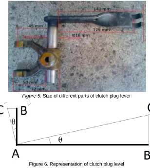
Figure 5. Size of different parts of clutch plug lever
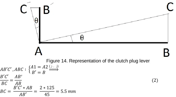
Figure 6. Representation of clutch plug level
To explain Figure (6) based on Figure (5), one should note:
1- The 125mm size is called the effective length of large arm of clutch plug (AB). 2- The 45mm size is called the effective length of small arm of clutch plug (𝐴′𝐵′). 3- BC refers to the extent of slipping at the end of large arm of clutch plug. 4- 𝐵′𝐶′represents the extent of slipping at the end of large arm of clutch plug.
As shown in Figure 6, the dark-colored BAB’ lines show the superficial shape of clutch plug level, and light-colored lines (i.e. 𝐶𝐴𝐶ꞌ) show the surficial shape of clutch plug lever after a movement with θ angle. The θ angle results because a 2mm looseness.
3- The clutch pedal level is measured by Collis (Figures 7 and 8).
110 Figure 8. Non-modified small arm of clutch pedal level
4- The length of arm limited by the support in the car itself is measured (i.e. AD is almost equal with 205mm; Figures 9 and 10).
Figure 9. Measurement of length of AD clutch pedal level compared with DE
Figure 10. Clutch pedal lever
5- The size and shape of lever shown in Figure 10 are detailed in Figure 11.
111 To explain the Figure 11 based on Figures 7 and 8, one should note:
1- AF refers to the length of large arm of clutch pedal (i.e. 335mm).
2- AD represents the length of arm limited by a support on car frame, and it is assumed to be equal with almost 205mm.
3- 𝐴𝐹ꞌ refers to the small arm of clutch pedal (i.e. 42mm).
4- FJ represents the skip size at the end of the large arm of the clutch pedal.
5- DE refers to the skip size at the end of the large arm of the clutch pedal. In this case, AD is the length of the arm.
6- 𝐹ꞌ𝐽ꞌ represents the skip size at the end of the small arm of the clutch pedal.
As shown in Figure 11, the dark-colored lines (i.e. FAF’) is clutch pedal lever while light-colored lines (i.e. JAJ’) is the clutch pedal lever after a movement with angle.
7- The coursing of the clutch pedal in a car like Pride is measured from an AD distance (Figure 12). The obtained value is almost 95mm.
Figure 12. Measurement of DE distance on car
8- To overcome the looseness between the bearing nail and the clutch plug, two holes with distinctive sizes at the finger tip of the clutch plug are made. Then, strong cylinder-like permanent magnets available in the market are inserted in these two holes so that the end of the magnet precisely touches the bottom of the clutch plugs. On the other hand, because the bottom of the clutch bearing is made of metal, the tip of clutch plug easily could be attached to it. As a result, the looseness of this part is eliminated.
Figure 13.Representation of holes in clutch plug
METHODOLOGY
Based on the obtained Figures and values, the following tests were used to evaluate different pieces of clutch system of a Pride as stated in the above section on materials and methods.
Test 1. The problem is to determine the extent of looseness at the end of large the arm of the clutch pedal when there is 2mm skip or release between the two plug tips and bearing nail. To solve this problem, based on the obtained sizes (Figure 5) for the clutch plug lever, we have:
𝐴𝐵 = 125 𝑚𝑚 𝐴𝐵′ = 45 𝑚𝑚
𝐵𝐶 =? 𝑚𝑚 (1)
𝐵′𝐶′ = 2 𝑚𝑚
112 Figure 14. Representation of the clutch plug lever
𝐴𝐵′𝐶′ , 𝐴𝐵𝐶 ∶ {𝐴1 = 𝐴2 𝐵′ = 𝐵
(ز . ز) ⇒ 𝐵′𝐶′
𝐵𝐶 = 𝐴𝐵ꞌ
𝐴𝐵 (2)
𝐵𝐶 = 𝐵′𝐶′ ∗ 𝐴𝐵 𝐴𝐵′ =
2 ∗ 125
45 = 5.5 𝑚𝑚
Based on the obtained values as shown in Figure 7 and 8, to solve the rest of problem of clutch pedal lever, we have:
𝐴𝐹 = 335 𝑚𝑚 𝐴𝐹′ = 42𝑚𝑚 𝐹𝐽 =? 𝑚𝑚
𝐹′𝐽′ = 𝐵𝐶 (3) 𝐹′𝐽′ = 5.5 𝑚𝑚
Based on the theorem of the similarity proportion of two triangles AFJ and AF’J’, to determine FJ of clutch pedal level, we have:
Figure 15. Representation of the clutch pedal lever
𝐴𝐹′𝐽′ , 𝐴𝐹𝐽 ∶ {𝐴1 = 𝐴2 𝐹′ = 𝐹
(ز . ز) ⇒
𝐹′𝐽′ 𝐹𝐽 =
𝐴𝐹′
𝐴𝐹 (4)
𝐹𝐽 = 𝐹′𝐽′ ∗ 𝐴𝐹 𝐴𝐹′ =
5.5 ∗ 335
42 = 43.8 𝑚𝑚
Test 2. The problem is to determine the extent of displacement at the end of the small arm of the clutch pedal when the total movement of the start of the clutch pedal from the desired point is 205mm.
To solve the problem based on the obtained sizes as shown in Figure 10 and regarding the fact that the size of skip at the start of the clutch pedal is 95 mm, we have:
𝐴𝐷 = 205 𝑚𝑚 𝐴𝐹′ = 42𝑚𝑚
𝐷𝐸 = 95 𝑚𝑚 (5)
𝐹′𝐽′ =? 𝑚𝑚
113 Figure 16. Representation of the clutch pedal lever
𝐴𝐹′𝐽′ , 𝐴𝐹𝐽 ∶ {𝐴1 = 𝐴2 𝐹′ = 𝐹
(ز . ز) ⇒ 𝐹′𝐽′
𝐹𝐽 = 𝐴𝐹′
𝐴𝐷 (6)
𝐹′𝐽′ = 𝐷𝐸 ∗ 𝐴𝐹′ 𝐴𝐷 =
95 ∗ 42
205 = 19.46 𝑚𝑚
Test 3. The problem is to determine the value of skip at the end of the small arm of the clutch plug when 19.34mm is added to the beginning of the large arm of the clutch plug lever by a clutch cable.
To solve the problem based on the obtained sizes as shown in Figure 5 and considering 19.56mm displacement at the beginning of the clutch plug lever, we have:
𝐴𝐵 = 125 𝑚𝑚 𝐴𝐵′ = 45𝑚𝑚
𝐵𝐶 = 19.46 𝑚𝑚 (7)
𝐵′𝐶′ =? 𝑚𝑚
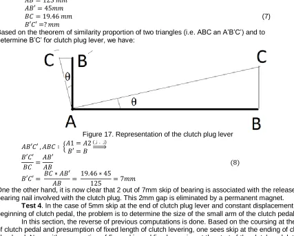
Based on the theorem of similarity proportion of two triangles (i.e. ABC an A’B’C’) and to determine B’C’ for clutch plug lever, we have:
Figure 17. Representation of the clutch plug lever
𝐴𝐵′𝐶′ , 𝐴𝐵𝐶 ∶ {𝐴1 = 𝐴2 𝐵′ = 𝐵
(ز . ز) ⇒ 𝐵′𝐶′
𝐵𝐶 = 𝐴𝐵′
𝐴𝐵 (8)
𝐵′𝐶′ = 𝐵𝐶 ∗ 𝐴𝐵′ 𝐴𝐵 =
19.46 ∗ 45
125 = 7𝑚𝑚
One the other hand, it is now clear that 2 out of 7mm skip of bearing is associated with the release of bearing nail involved with the clutch plug. This 2mm gap is eliminated by a permanent magnet.
Test 4. In the case of 5mm skip at the end of clutch plug lever and constant displacement at the beginning of clutch pedal, the problem is to determine the size of the small arm of the clutch pedal lever.
In this section, the reverse of previous computations is done. Based on the coursing at the head of clutch pedal and presumption of fixed length of clutch levering, one sees skip at the ending of clutch plug level. Now, with presumption of 5mm skip and fixed coursing at the start of the clutch pedal, the size of the small arm in the clutch pedal level is obtained to be designed later.
To solve the problem based on determined sizes (Figure 5) and 5mm skip at the ending of clutch plug lever, we have:
114
𝐵𝐶 =? 𝑚𝑚 (9)
𝐵′𝐶′ = 5 𝑚𝑚
Based on the theorem of the similarity proportion of two triangles ABC and A’B’C’ for the determination of BC of the clutch plug lever, we have:
Figure 18. Representation of clutch plug lever
𝐴𝐵′𝐶′ , 𝐴𝐵𝐶 ∶ {𝐴1 = 𝐴2 𝐵′ = 𝐵
(ز . ز) ⇒
𝐵′𝐶′ 𝐵𝐶 =
𝐴𝐵′
𝐴𝐵 (10) 𝐵𝐶 = 𝐵′𝐶′ ∗ 𝐴𝐵
𝐴𝐵′ = 5 ∗ 125
45 = 13.8 𝑚𝑚
In the following, the calculations are associated with the arm of the clutch pedal lever:
𝐴𝐷 = 205 𝑚𝑚 𝐴𝐷′ =? 𝑚𝑚 𝐷𝐸 = 95 𝑚𝑚
𝐷′𝐸′ = 𝐵𝐶 (11)
𝐷′𝐸′ = 13.8 𝑚𝑚
Based on the theorem of the similarity proportion of two triangles ADE and A’D’E’, for the determination of AD’ of the clutch pedal lever, we have:
Figure 19. Representation of the clutch pedal lever
𝐴𝐷′𝐸′ , 𝐴𝐷𝐸 ∶ {𝐴1 = 𝐴2 𝐷′ = 𝐷
(ز . ز) ⇒ 𝐷′𝐸′
𝐷𝐸 = 𝐴𝐷′
𝐴𝐷 (12) 𝐴𝐷′ = 𝐷′𝐸′∗𝐴𝐷
𝐷𝐸 = 13.8∗205
95 = 29.7 𝑚𝑚≅ 30 mm
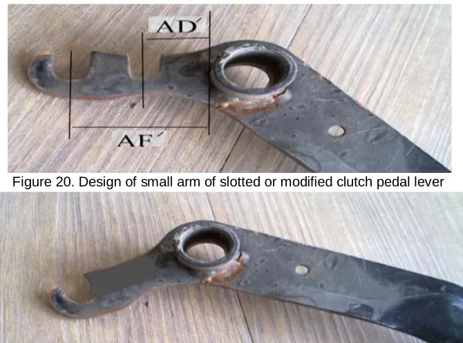
The calculations show that for 5mm skip, one should generate another opening in the vicinity of previous opening shown in Figure 20 at the distance of 30cm. From now on, this type of pedal shown in Figure 20 is called slotted clutch pedal while Figure 21 shows a non-slotted clutch pedal. In this regard, AD’ distance is the modified distance and AF’ refers to the distance of the small arm of the small pedal lever without any modification. Now, the AD’ distance is represented by C’ and AF’ distance is depicted by c.
Therefore, we have:
115 Figure 20. Design of small arm of slotted or modified clutch pedal lever
Figure 21. Design of the small arm of non-slotted and non-modified clutch pedal lever
Now, the comparison and calculation of force in levering the clutch system in the case of slotted and non-slotted clutch are done.
Test 5. The problem is to determine reduction of force in the case of reducing the size of small pedal from 43 to 30mm.
To respond this question, one should calculate torque and generated forces F2 and F3 as a result of F1 in clutch pedal lever. By equating F2 and F3, one could obtain the difference ration of F1 (Figure 22).
Figure 22. Representation of the division of clutch pedal lever First, F2 is calculated:
2 = M 1 M (14) ) 2 L 1 + * (L 2 = F 3 * L 1 F ) 2 L 1 + ) / (L 3 * L 1 = (F 2 F
Then, F3 is calculated: 2 = M 1 M (15) 2 * L 3 = F 3 * L 1 F 2 ) / L 3 * L 1 = (F 3 F
On the other hand, as defined in default manner, we have:
𝐴𝐹′
= C = 2 L 1 + L
(16) L2 = C′= 𝐴𝐷′
We know that the ration of C to C’ is C’=5/7 *C because 30 is divided by 42 and one obtains the ratio of 5/7.
Now, equating F2 and F3, the difference ratio of F1 will be determined: F2=F3
116 (F1*L3) / C = (F1*L3) / (5/7*C) ⇉ F1 = F1/(5/7) (18)
Test 6. All steps of modifying clutch system were practically performed on the car to be tested. The smoothness of clutch after modifying it was acceptable.
RESULTS AND DISCUSSION
1- The calculations of test 1 show that for a 2mm looseness at clutch plug, a 43.8 release at the end of the large arm of the clutch pedal is generated.
2- The calculations of test 2 show that after the total movement of the head of the clutch pedal from a distance of 205mm to 95mm, one could observe a 19.46mm movement at the end of the small arm of the clutch pedal.
3- The calculations of test 3 show that during test 2, a 95mm displacement of the head of the clutch pedal is followed by 7mm skip at the end of the small arm of the clutch plug lever.
4- The calculations of test 4 show that by eliminating a 2mm looseness of bearing nail, one could reduce the size of the small pedal from 42 to 30 mm. Thus, one can make an opening in clutch pedal after reducing the size of pedal by 12mm.
5- The calculations of test 5 show that with reduced size of small arm of clutch pedal, the force applied on will be 5/7 (i.e. 70%) of the force applied on non-modified pedal. In other words, 30% of the compressive force applied on the clutch pedal is reduced.
6- Test 6 showed that the final clutch smoothness after modifying it was acceptable.
CONCLUSION
The conclusions that could be drawn from the examination and evaluation of clutch system are the following:
1- Almost 30 percent of the force applied clutch pedal was reduced.
2- For physically weak or small individuals, especially those with weak leg muscles, using clutch could be easily done.
3- The comfort and ease of driver is added, and positive feeling and energy are what he gets. 4- Before modification and in the move-forward step of bearing, two clutch heads pressed the bottom
of the bearing, and in the return step of bearing, the clutch heads depended on bearing nail to finish the returning action of the bearing. But after modification, the bearing retrieving action does not need any bearing nail and bearing is attached to the clutch plugs and returned backwards. Therefore, the magnetization of clutch plug leads to a case in which the bearing with clutch plug performs the go-forward and return actions without releasing. As a result, the elimination of this release enables the reduction in length of the small arm of the clutch pedal.
REFERENCES
Ghanbari, A., Ghaderi & Allah Yari, M. (2011). Effect of unevenness of surface of shot on frictional torque, Sixth National Conference of Maintenance, Tehran.
Mohammadi Bosari, M. (1994). A discussion on power transmission, Farhang Press.