Error Reduction Approach for Performance Improvement
in CSK Systems
1 The Smart Radio Communication System Lab., Department of Electrical and Electronic Engineering, Chungbuk National University, Cheongju, Chungbuk, Rep. of Korea.
2 The Chung-Cheong Project Evaluation Management Institute New IT Industry, Cheongju, Chungbuk, Rep. of Korea.
* Corresponding author. Tel.: +82-10-8802-5823; email: [email protected] Manuscript submitted September 9, 2014; accepted April 2, 2015.
doi: 10.17706/ijcce.2015.4.6.390-396
Abstract: Color shift keying (CSK) is a modulation method for transmitting data imperceptibly through changes in the color of the output light in VLC systems. CSK modulation transmits information through color properties of light of RGB light emitting diode. Symbol position using RGB is represented in three-dimensional space. However, the symbol decision process is a color two-dimensional coordinate system. Thus, when converting RGB values, loss due to a decrease in dimension occurs. Also, when converting the xy coordinates in the RGB space, a color shift in the received data occurs due to noise. In this paper, we propose a received symbol determination method to reduce error in determining the symbol in the color space. We analyzed bit error rate performance of the proposed method and demonstrated, though numerical simulation, the possibility for error reduction.
Key words: Visible light communications, color shift keying, CIE 1931, color matching.
1.
Introduction
Recently, various analog lights that have been used in association with vehicle and indoor are gradually replaced by LED lighting. LEDs are used not only for illumination but also for many products such as monitors and TV, smart phones, cars, and others. In recent years, many attempts to LED convergence of IT technology have been made [1], [2]. A fusion of communication and lighting, visible light communication (VLC) has emerged among them [3]. VLC is considered an attractive technology because it can be used for both lighting and communication at the same time. VLC is a technique that utilizes a visible light wavelength region (380nm ~ 780nm) that can be visually recognized, and which is applied to the communications. Also, it is a method that is most likely worthwhile for wireless communication which can guarantee the communication connection information. A new communication technique using visible light is proposed under the IEEE802.15.7 task group [4], [5]. Color shift keying (CSK) modulation has been proposed for high speed, point-to-point communications as described in the PHY III specification layer of the standard. In order to provide sufficient data transfer rates to support multimedia services for video and audio, this standard describes the use of visible light communications that merges lighting applications and data communications with each other [6]. CSK is a modulation method for transmitting data imperceptibly through changes in the color of the output light in VLC systems. The physical specification uses CSK as a codification system. CSK modulation transmits the information through the color properties of red, green,
and blue (RGB) LED. A CSK constellation is defined by a combination of three color bands of the respective three color light sources. In order to improve the reliability of a visible light communication system, to accurately analyze the changes in the quality of the communication channel between the terminal and the LED lighting is important. In this paper, we propose a received symbol determination method to reduce error in determining the symbol in the color space. Symbol position using RGB is represented in three-dimensional space. However, the symbol decision process is a color two-dimensional coordinate system. Thus, in converting RGB values, loss due to a decrease in dimension occurs. We analyzed the bit error rate (BER) performance of the proposed method and demonstrated by numerical simulation the possibility for error reduction.
This paper is organized as follows. Section 2 gives the system model for CSK. The proposed error reduction approach is analyzed in Section 3. Numerical and simulation results are given in Section 4. Finally, Section 5 concludes this paper.
2.
System Model
This section explains CSK system model. RGB LEDs are used to present colors because the color combination can produce any color according to such chromaticity diagrams as the CIE 1931. CSK is based on change in color to transmit information. We assume n LEDs with different wavelength characteristics and n different photo detectors (PDs). At the transmitter the data bits are set into symbols of k bits and mapped to RGB intensities required to produce a unique color which is represented by a pair of chromaticity values. And the symbols are then transmitted to (R, G, B) values which represent the intensity ratio of the red, green and blue light emitted from the RGB LED respectively. On the receiving side, an optical filter of the photo diode filters only the light of the corresponding wavelength. The photo diode is used at the receiving side in order to detect instantaneous changes in incident light intensity on the surface. A
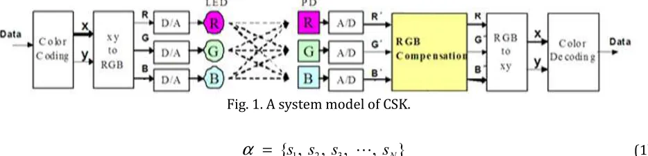
receiver approach based on three RGB components is used instead of the standard XY International Commission on Illumination (CIE) receiver. The color component is generated using a linear combination of the wavelengths of red, green, and blue, but this release is mapped to a two-dimensional symbol using the transformation defined in the CIE1931 color space. A system model for CSK is in Fig. 1, where x, y and R, G, B
represents chromaticities and intensities at the transmitter, respectively, and R', G', B' are the intensities at the receiver. For an N symbol CSK system, data are first mapped onto the constellation.
Fig. 1. A system model of CSK.
1 2 3
{ , , ,
s s
s
, }
s
Nα
=
⋯
(1)In the color coding phase, binary data is mapped to the xy coordinate. And the chromaticity of these data will be converted to intensity Pi, Pj and Pk (or R, G, B) using the following set of equations [4].
i i j j k k
x = Px + P x + P x (2)
i i j j k k
1
i j k
P + P + P = (4)
- 0 .2 0 0 .2 0 .4 0 .6 0 .8 1
- 0 .2 0 0 .2 0 .4 0 .6 0 .8
x
y
C S K c o n ste l l a ti o n
i b a n d j b a n d k b a n d C S K S y m b o l s
I J
K A
B C
D
P0
P1 P2
P3
P4 P5
P6 P7
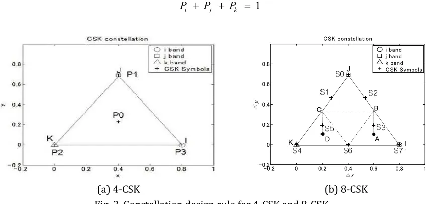
(a) 4-CSK (b) 8-CSK Fig. 2. Constellation design rule for 4-CSK and 8-CSK.
The (xi, yi), (xj, yj) and (xk, yk) refer to the chromaticity values at the central wave lengths of the three
different LEDs used in the system. Chromaticity of the central wavelength is changed when using an LED of a different color. Fig. 2 shows the shape of the constellation of the 4-CSK and 8-CSK basic standards for VLC. Coordinates are converted to a three-dimensional RGB space. The formula for the tristimulus values X, Y, Z
from the x, y coordinate values are as follows.
, (1 )
Y Y
X x Z x y
y y
= = − − (5)
As in (6) is a method of obtaining the R, G, B values from X, Y, Z values [7].
2.3707 0.9001 0.4706
0.5139 1.4253 0.0886
0.0053 0.0147 1.0094
R X Y Z
G X Y Z
B X Y Z
= − −
= − + +
= − +
(6)
Now, these symbols are transmitted over an additive white Gaussian noise (AWGN) channel noise. The photo diode is used at the receiving side in order to detect instantaneous changes in incident light intensity on the surface. A receiver optically filters the received signal to separate the red, green, and blue channels, and three photo detectors measure the received intensity in each of these bands. As in (7) is a method of obtaining the X, Y, Z values from R, G, B.
0.4887 0.3107 0.2006
0.1762 0.8130 0.0108
0.0102 0.9898
X R G B
Y R G B
Z G B
= + +
= + +
= +
(7)
The minimum squared Euclidean distance f(u) is
( )
arg min
,
I
v F
f u
u v
u
I
∈
=
−
∈
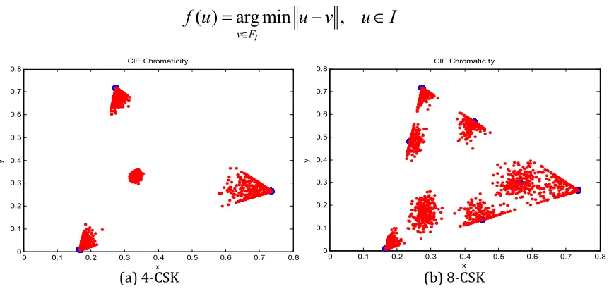
(8)(a) 4-CSK (b) 8-CSK
Fig. 3. Symbols received an AWGN channel environment is depicted in CIE 1931 space (SNR = 10dB, Blue circles indicate the position of the symbols transmitted. Red dots indicate the received symbols).
Let I denote the transmitted symbol set for 4-CSK and 8-CSK. FIdenotes the set of received symbols. Let
f(u) denote the closest transmitted symbol of u, and
⋅
is the Euclidean distance. After acquiring thesymbol constellation received appropriate, it may be inverted to generate a symbol constellation sent conversion is designed. It can be seen that the position of the received symbols may appear disproportionate under the influence of noise. Therefore, it is necessary to minimize the losses associated with a decrease in dimension in order to reduce error in CSK-based visible light communication.
3.
Proposed Error Reduction Approach
This section explains error reduction approach for improving the system performance of CSK. In the existing methods, after the received RGB values are converted to XYZ values with in (7), the symbol decision is performed in the CIE1931 color space. In the CIE 1931 color space, the angle between the lines representing the color is not uniform. Therefore, since the color difference is not uniform, when applying the minimum Euclidian distance, error probability is high. The proposed error reduction approach is divided into four steps
1) N symbols map the xy coordinates of the color space according to the design rule as shown in Fig. 2.
2) The mapped symbols
α
= { , , , s s1 2 s3 ⋯, }sN are converted to the RGB color space by using (5) and(6).
3) For color correction, apply the Euclidean distance between the transmitted symbols and received symbols in the RGB space. Symbols that are received are determined from the transmission symbol’s closest distance.
4) After converting the xy color space in the RGB space, the symbols are compared with the original signal by decoding.
As the distance between symbols is large, the probability of symbol error would be low. Similarly, because the symbol decision area will increase to three-dimensional, more accurate distance calculation is possible. Therefore, the performance of the communication will be improved. Fig. 4 shows RGB space symbols received in an AWGN channel environment. Blue stars indicate the position of the received symbols. The
0 0.1 0.2 0.3 0.4 0.5 0.6 0.7 0.8
0 0.1 0.2 0.3 0.4 0.5 0.6 0.7 0.8
CIE Chromaticity
x
y
0 0.1 0.2 0.3 0.4 0.5 0.6 0.7 0.8
0 0.1 0.2 0.3 0.4 0.5 0.6 0.7 0.8
CIE Chromaticity
x
transmitted symbols are subject to a color shift phenomenon due to noise, as shown in Fig. 4, which also shows the extent of the spread of the received symbols.
(a) 4-CSK (b) 8-CSK
Fig. 4. Symbols received an AWGN channel environment is depicted in RGB space (SNR = 10dB, Blue stars indicate the position of the received symbols).
4.
Simulation Results
In this section, we analyze BER performance of the proposed method compared to existing CSK methods. We consider only the AWGN channel. For a practical system, the noise power is directly proportional to the intensity of the incident light across the surface of the PD. However, noise strength in the indoor environment was applied by assuming AWGN. The total optical power to be sent in any instance is equal to 1 watt in CSK systems i.e. R+G+B = 1. This eliminates any kind of flicker problems associated with intensity variations [8]. In this study, in order to characterize the system performance of uncoded systems evaluation is determined without the encoder. Table 1 shows the pair of chromaticities used to represent each CSK symbol for 4-CSK and 8-CSK. Table 1 also shows the intensities, which can be calculated from chromaticities by using (2), (3) and (4). However, the output power of the individual LED will vary, as can be seen from Table 1.
Table 1. Chromaticity Values and RGB Intensities for Different Symbols in 4-CSK and 8-CSK Modulations
Symbol x y R
(w/m2)
G
(w/m2)
B (w/m) 4 -C S K
S0 0.167 0.009 0 0 1
S1 0.274 0.717 0 1 0
S2 0.735 0.265 1 0 0
S3 0.333 0.333 1 1 1
8
-C
S
K
S0 0.167 0.009 0 0 1
S1 0.238 0.481 0 0.68 0.32
S2 0.428 0.566 0.46 0.54 0
S3 0.274 0.717 0 1 0
S4 0.563 0.298 0.79 0.11 0.1
S5 0.280 0.170 0.26 0.15 0.58
S6 0.451 0.137 0.64 0 0.36
S7 0.735 0.265 1 0 0
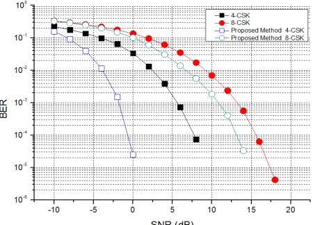
Fig. 5 shows the BER performance comparison of an M-CSK system based on the method provided in an AWGN channel. In the figure, the squares and circles on the graph show 4-CSK and 8-CSK, respectively. BER is based on 10-4, and for 4-CSK and 8-CSK, compared to the conventional method, there is a performance
improvement of 3dB and 6dB, respectively. The width of the improvement of the performance in 4-CSK is wider than the 8-CSK. As shown in Fig. 2, the distance between symbols in 4-CSK is wide compared to 8-CSK. So, the probability of symbol error occurs is low. The proposed errors reduction approach dose not directly determine the symbols from CIE1931 color space, but applies the Euclidian distance in order to color correct in the RGB three-dimensional space to determine the received symbols close to the transmitted symbols. Then, in order to convert the xy coordinate, it is possible to reduce error.
Fig. 5. BER performance comparison of M-CSK system based on proposed method in AWGN channel.
5.
Conclusion
A visible light communication system is new wireless communication technology using LED light and a PD that can recognize the ON / OFF of light. In order to improve the reliability of a visible light communication system, to accurately analyze the changes in the quality of the communication channel between the terminal and the LED lighting is important. In this paper, we proposed an approach for error reduction in order to improve the performance of VLC based on CSK. The BER performance analysis for both of the CSK schemes was presented for an AWGN channel. Applying the proposed method to 4-CSK and 8-CSK, improved performance by about 3dB and 6dB, respectively, compared to the conventional method. The proposed error reduction approach dose not directly determine symbols from the CIE1931 color space, but applies the Euclidian distance in order to color correct in the RGB three-dimensional space to determine the received symbols close to the transmitted symbol. Therefore, because the symbol decision area will increase to three-dimensional, more accurate distance calculation is possible. Therefore, the performance of the communication will be improved.
In future research, we will seek color difference correction technology, effective color control, and a method of reducing complexity.
References
[1] Son, D.-K., Cho, E.-B., Moon, I.-K., Park, Y.-S., & Lee, C.-G. (2011). Development of an illumination measurement device for color distribution based on a CIE 1931 XYZ sensor. J. Opt. Soc. Korea,15, 44-51. [2] Bouchet, O., et al. (December 2010). Visible-light communication system enabling 73 Mb/s data
streaming. Proceedings of IEEE GLOBECOM Workshop Opt. Wireless Communication (pp. 1042–1046). [3] Komine, T., & Nakagawa, M. (2004). Fundamental analysis for visible-light communication system using
LED lights. IEEE Trans. Consumer Electron, 50, 100-107.
Short-Range Wireless Optical Communication Using Visible Light. IEEE Standard 802.15.7-2011.
[5] Kwon, H.-C., et al. (May 2008). Modulation issues of visible light communication. Proceedings ofIEEE
P802.15 Working Group for Wireless Personal Area Networks (WPANs).
[6] Vucic, J., Kottke, C., Nerreter, S., Langer, K.-D., & Walewski, J. (2010). 513mbit/s visible light communications link based on dmt-modulation of a white led. Journal of Lightwave Technology,28(24), 3512–3518.
[7] Pascale, D. (2003). A review of RGB color spaces. Babel Color Company: 1-35.
[8] Rajagopal, S., Roberts, R., & Lim, S.-K. (March 2012). IEEE 802.15.7 visible light communication: modulation schemes and dimming support. Communications Magazine, IEEE, 50(3), 72–82.
Byung Jin Lee received the BS degree in information and communication engineering form Chungbuk National University, Korea, in 2013. He is currently working towards the MS degree with the School of Wireless Communication Engineering of Chungbuk National University. His research interests include visible light communication, cognitive radio, power line communication.
Won Ho Jeong received the BS degree in information and communication engineering form Chungbuk National University, Korea, in 2011. He is currently working towards the MS degree with the School of Wireless Communication Engineering of Chungbuk National University. His research interests include MIMO wireless channel, DDC and digital radio.
Yong Won Kim received the MS degree with the School of Wireless Communication Engineering of Chungbuk National University. He worked for ETRI from 2004 to 2007. He is currently working as a senior researcher at the Chung-Cheong Project Evaluation Management Institute New IT Industry. His research interests include visible light communication, cognitive radio, power line communication.