Feasibility Study of React-and-Wind Method for Helical Coils
Wound from Cable-in-Conduit Conductors
∗
)
Shinsaku IMAGAWA
National Institute for Fusion Science, 322-6 Oroshi, Toki, Gifu 509-5292, Japan SOKENDAI, Department of Fusion Science, 322-6 Oroshi, Toki, Gifu 509-5292, Japan
(Received 30 November 2015/Accepted 9 March 2016)
Design study on react-and-wind method for helical coils wound from cable-in-conduit conductors has been carried out. In this concept, the conductor is wound after heat treatment with being pulled aside from a reel, that is, being twisted. Since the superconducting wires in the conduit are multi-stage twisted, the effect of twisting the conductor on the strain of the wires is considered to be small. Furthermore, if tension is added on the wires by twisting the conductor, the compressive strain due to thermal contraction of the wires is reduced, and the critical currents of CIC conductors can be increased with the react-and-wind method. In order to examine the effect of twisting the conductor on the strain of the wires, experimental study with a model CIC conductor has been carried out. The experimental results show that the tensile strain is added in the wire by twisting the conduit in the same direction as the wire twisting direction.
c
2016 The Japan Society of Plasma Science and Nuclear Fusion Research
Keywords: cable-in-conduit conductor, fusion reactor, helical coil, react-and-wind, superconducting magnet DOI: 10.1585/pfr.11.2405058
1. Introduction
Design studies on heliotron reactors have been carried out [1–3]. In order to attain a sufficient space for blankets and to reduce the average neutron flux, the major radius is set at 14 to 17 m with the central toroidal field of 6 to 4 T. Both the major radius and the magnetic energy are approx-imately three times as large as those of ITER.
Cable-in-conduit (CIC) conductors made of a multi-stage twisted cable of superconducting wires within a tube-like conduit have been developed for large superconduct-ing magnets because of high mechanical strength, small AC losses, and high cryogenic stability. Since the tech-nology related to CIC conductors with Nb3Sn wires has been widely advanced through the construction of ITER, they should be the first candidates for the magnets of the next fusion reactors. The major disadvantage is reduc-tion of critical current (Ic) caused by large compressive strain due to heat treatment up to 650◦C for production of the A15 phase. In the case of the SUS316 conduit, the compressive strain in the superconductor such as Nb3Sn or Nb3Al exceeds 0.7%, and their critical current is con-siderably degraded. In order to prevent further increase of the strain, the heat treatment is usually carried out af-ter winding, which is called the “wind-and-react” method. The “react-and-wind” method, however, is preferred for a helical coil to avoid a huge oven for the heat treatment. In this concept, the heat treatment of a CIC conductor is carried out on a bobbin, the circumference of which is the author’s e-mail: [email protected]
∗)This article is based on the presentation at the 25th International Toki
Conference (ITC25).
same as the length of one pitch of the helical coil [2]. Af-ter that, the conductor is wound in the helical coil case with being pulled aside, that is, being twisted. Since the super-conducting wires in the conduit are multi-stage twisted, the effect of twisting the conductor on the strain of the wires is considered to be small. Furthermore, if the compres-sive strain due to thermal contraction of the wires is re-duced by twisting the conductor,Icof CIC conductors can be increased. In this paper the concept of react-and-wind method for a large helical coil and the expected effect on
Icare discussed.
2. Concept of React-and-Wind
Heli-cal Coil
Major parameters of two typical designs of helical coils for a helical power plant are listed in Table 1 [2], compared with the ITER-Toroidal Field (TF) coils [4]. The parameters are determined under these conditions: the en-hancement factor of energy confinement of 1.12 to the ISS04 scaling [5], parabolic distribution of both the plasma density and temperature, density limit of the Sudo scal-ing [6], averageβ(ratio of plasma pressure to the central magnetic pressure) of 5%, minimum space for blankets of 1.1 m, helium ash ratio of 3%, oxygen impurities ratio of 0.5%, and alpha particle heating ratio of 90%. The con-figuration of coils is similar to the Large Helical Device (LHD), as shown in Fig. 1. The lead angle of the heli-cal coil is defined as the pitch parameterγ=(mac)/(lRc), wherel,m,Rc, andacare the pole number, the pitch num-ber, the coil major radius, and the coil minor radius,
re-c
2016 The Japan Society of Plasma
Table 1 Specifications of helical coils wound from CIC conduc-tors for an LHD-type power plant.
Fig. 1 Cross-section of LHD-type fusion reactor. Two helical coils and two sets of poloidal coils are fixed from a mag-net support.
spectively. The high current density jof the helical coil is useful to enlarge the space for blankets and for main-tenance. jis, however, restricted mainly by mechanical strength and quench protection. Considering the space for the structural materials inside the winding, jof the wind-ing, which consists of the conductors, structural materials between them, and insulators, is set at 25 A/mm2 in this study.
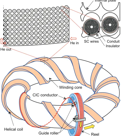
The length of cooling channel of a CIC conductor is limited by the pressure drop for the necessary mass flow. In the case of the peak nucleate heating of 1 kW/m3, the maxi-mum length is estimated at around 500 m. Since the center-line of the helical coil is five times as long as the ITER-TF coil, parallel winding is necessary in addition to adopting a large current conductor of almost 100 kA. Considering the periodicity of 10, five-in-hand is proposed [2], and a cooling path length is within 500 m. An internal plate, as
Fig. 2 A concept of winding a helical coil from CIC conductors with react-and-wind method.
shown in Fig. 2, is useful for the parallel winding, because the position of each conductor is determined by a groove of the internal plate. Besides, the internal plate is useful to reduce the stress caused by the electromagnetic force in the insulation around the conductor.
A winding method is a critical issue for helical coils. In the case of the LHD helical coil, a special winding ma-chine was developed for forming NbTi conductors plas-tically into helical shape with a shaping head. Since the plastic deformation of the wires is not allowed for Nb3Sn or Nb3Al conductors, the allowable strain after heat treat-ment is considered to be within the range of 0.5% [7, 8]. A proposed winding method is as follows: 1) CIC conductors are heated for reaction of the A15 phase on a bobbin, the circumference of which is the same as the length of one pitch of the helical coil. 2) The conductors are transferred to a reel that revolves through the helical coil. 3) The con-ductors are pulled aside by a set of guiding rollers, wrapped with glass tapes, and wound in grooves of the internal plate that is supported from a winding core. 4) After winding all the turns in a layer, the next internal plates are assembled and welded each other. 5) After winding all the layers, the helical coils are vacuum impregnated with epoxy resin.
Fig. 3 A concept of assembling helical coils and the surrounding components.
Fig. 4 Torsional strain and bending radius of the conductor at the inner corner of the helical coil in Table 1. The widths of the coils are 1.706 and 1.656 m forγ=1.15 and 1.20, respectively. Each height is half of the width.
poloidal coils are installed. Fourthly, a vacuum chamber and a thermal shield for the magnets are assembled. In parallel, permanent blankets are installed and welded each other. Finally, breeding blankets and divertor cassettes are installed from maintenance ports. A sliding mechanism for the heavy components must be developed.
The torsional strain of the conduit is given byrθwhere
randθare the radius of the conduit and the torsional an-gle per unit length. The torsional strain and the bending radius of the helical coils in Table 1 are shown in Fig. 4. The bending strain during winding is less than 0.05%. The highest torsional strain of the conduit is almost 0.7% that induces the highest tensile strain in the angle ofπ/4 from the longitudinal direction of the conductor. According to Mohr’s stress circle, the tensile strain is zero in the longitu-dinal and transverse directions. Since the superconducting wires are twisted, they are inclined to the longitudinal di-rection of the conduit with the angleη, as shown in Fig. 5. Assuming that the wires behave as a monolithic metal, the
Fig. 5 Torsional strain in a conduit and longitudinal strain in wires of a CIC conductor.
Table 2 Major parameters of the helical winding model.
longitudinal normal strain of the wire is given by εwire= rwireθ
2 (1+ν)cos π
2 −2η
, (1)
whererwireandνare the radius of the wire and Poisson’s ratio, respectively. In reality, the strain must be reduced by slippage of the wires against the conduit. The most impor-tant point of Equation (1) is that tensile strain can be added in the wire by twisting the conduit in the same direction as the wire twisting direction.
3. Trial of Winding Model Coil
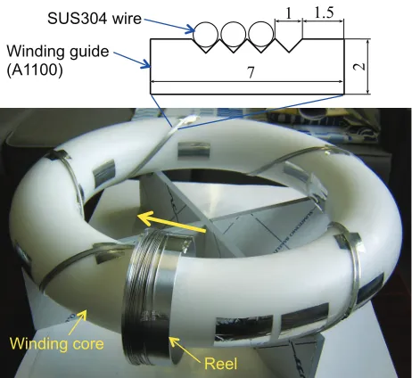
In order to examine the feasibility of the concept of helical winding, a model of winding core is prepared as shown in Fig. 6. The dimension is 1/84 of the HC_γ1.20 in Table 1, as shown in Table 2. The winding core is made of polyacetal. Four V-shaped grooves of 0.5 mm depth are machined in a winding guide made of an A1100 bar. The winding guide is wound on the core with being bent and twisted by hand. Its trajectory is shifted by a few mm to the geodesic line from the designed position due to the ten-sion in jointing both the terminals. An SUS304 wire of the diameter of 0.9 mm is wound once on a reel of the radius of 62 mm. The reel is moved by hand along the core as the wire on the reel is released step by step. The wire is set-tled smoothly in the grooves, as shown in Fig. 7, by being fixed with tapes by four positions per pitch. This method is expected to be feasible.
4. E
ff
ect of Twisting Conductor
Fig. 6 A model for helical winding. An SUS304 wire simulates a CIC conductor.
Fig. 7 Trial of helical winding. The wire is wound in the grooves by three turns.
was made by twisting together three copper wires, each length of which is 600 mm. One triplet consists of two copper wires and a pair of leads of two single-axis strain gauges, which are attached on the two copper wires near the center in length to measure the longitudinal strain of the wires. Secondly, six sub-cables were made by twisting four triplets per sub-cable as the 2nd stage. Thirdly, as the 3rd stage, six sub-cables were wound around an SUS304 pipe of the diameter of 6 mm that simulates a central chan-nel for coolant, as shown in Fig. 8. All the twisting direc-tions are right hand, and the average twisting pitch lengths of the 1st, 2nd, and 3rd stages are 33.4, 50.4, and 130 mm, respectively. Finally, the whole assembly was inserted into an SUS304 conduit, on which two three-axis strain gauges are attached at the center in length. The length, outer di-ameter, and thickness of the conduit are 500 mm, 17.3 mm and 1.65 mm, respectively. Flanges had been welded at both ends of the conduit. The wires are fixed to the conduit with epoxy resin at both ends. Since the model conductor was not compacted because of difficulty, the void fraction
Fig. 8 Schematic drawing (a) and photograph of the cable (b) of model CIC conductor for twisting tests.
Fig. 9 A twisting jig for a model CIC conductor.
is around 50%.
The model conductor is twisted or pulled and pushed with a special tool as shown in Fig. 9. The upper flange of the conductor is fixed to an outer cylinder of the tool, and the lower flange is fixed to a rotating stage. The rotating angle is controlled with a set of worm gear and wheel. The longitudinal force to the conductor can be varied with the stud bolts at the upper position.
Figure 10 shows the strain change in the conduit dur-ing bedur-ing twisted with the loose stud bolts. In the case of pure torsion, normal strains inXandY directions are zero, and normal strain inXYdirection is given by
εXY=−
rconduitθ
2 (1+ν), (2)
Fig. 10 Normal strain in the outer surface of the conduit with be-ing twisted. S1 and S2 are three-axis strain gauges on the conduit, andXandYare in the axial and circumferential directions, respectively.
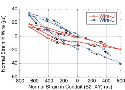
Fig. 11 Longitudinal normal strain in wires versus the normal strain inXYdirection in the conduit.
0.3. The certain strain inXorY direction is considered to be induced by rotation of the gauge from the ideal angle.
Here, the average strain in a sub-cable is considered. The averageη of the centerline of a sub-cable is 13 de-grees, and the radius is 5.0 mm. Then, the average strain is estimated at 1/4 of the maximum strain in the conduit from (1). Figure 11 shows longitudinal normal strain in the wires versus normal strain in the conduit inXYdirection. The tensile or compressive strain is induced in the wire by twisting the conduit in the same or counter direction to the wire twisting direction, respectively, as expected. The strain change of wires is, however, less than 1/10 of the conduit. Besides, the strain change shows a hysteresis loop that should be caused by friction among the wires and be-tween the wire and the conduit. Therefore, the wires are considered to slip against the conduit to reduce the strain.
The larger void fraction is considered to allow larger slip-page.
Since the strain change of wires is small during twist-ing the CIC conductor, the react-and-wind method is ex-pected to be applicable for a helical coil. Furthermore, slight improvement ofIcis expected by selecting the twist-ing direction of the Nb3Sn wires same as the twisttwist-ing di-rection of the CIC conductors during the helical winding. In order to confirm the effect, Ic measurement of Nb3Sn CIC conductors is planned using small coils in spring-shape. The torsional strain in the conductor is controlled with changing the length of coils.
5. Summary
A react-and-wind method is proposed for a large heli-cal coil wound from CIC conductors, the major disadvan-tage of which is the decrease ofIccaused by compressive strain due to thermal contraction due to heat treatment up to 650◦C. Since superconducting wires are twisted in the conduit, their strain is expected to be changed by twist-ing the conductors. The experimental study with a model CIC conductor shows that the tensile strain is induced in the wire by twisting the conduit in the same direction as the wire twisting direction, as expected. In this experi-ment, the amounts of change of longitudinal normal strain in wires are in the order of 1/10 of the highest normal strain in the conduit. The change of strain in the wires is considered to be lessened by slippage of the wires to the conduit. Since the compressive strain in the wires can be slightly lessened by twisting the conductor, the react-and-wind method is expected to be applicable for the helical coil without degradation or with slight improvement of the conductor performance.
Acknowledgment
This research was funded by MEXT Grant #15K06654 and partly supported by NIFS Collabo-ration Research program (UFAA001).
[1] A. Sagaraet al., Fusion Eng. Des.89, 2114 (2014). [2] S. Imagawa, A. Sagara and Y. Kozaki, Plasma Fusion Res.
3, S1050 (2008).
[3] H. Tamuraet al., Fusion Eng. Des.89, 2336 (2014). [4] N. Mitchellet al., Fusion Eng. Des.66-68, 971 (2003). [5] H. Yamadaet al., Nucl. Fusion45, 1684 (2005). [6] S. Sudoet al., Nucl. Fusion30, 11 (1990).
[7] A. Awajiet al., Supercond. Sci. Technol.18, S313 (2005). [8] M. Jewell, P. Lee and D. Larbalestier, Supercond. Sci.