7 |
P a g e
STUDY OF AUTOMATIC TRANSMISSION BASED ON
ELECTRONIC CONTROL SYSTEM
Prakash Kumar Sen
1, Omprakash Baghel
2, Shailendra Kumar Bohidar
31
Student of M. Tech. Manufacturing Management, BITS Pilani
2
Student of Mechanical Engineering, Kirodimal Institute of Technology, Raigarh, (India)
3
Ph.D. Research Scholar, Kalinga University, Raipur
ABSTRACTS
Since 1980s, the electronic control units of automatic transmissions have been greatly advanced to make smooth
gear shifting and improve fuel economy. Along with it, the solenoid valves as electro-hydraulic actuators have
been rapidly developed which have high pressure and large flow capacity. In these days, it is not an expensive
solution to adopt more electro-hydraulic actuators to get the better performance of the automatic transmission.
This paper introduces a new scheme of full electronic control system, direct active shift control, using the
proportional control solenoid valves to control the pressure of each friction element independently and without
any passive hydraulic or mechanical component. At first, it reviews the structures of widely used control systems
from the old-fashioned to the modern. Next, the concept of the direct active shift control scheme is introduced
and the performance of the actuators discussed. Finally, you can show the simple test results compared with a
commercially announced system recently developed and be sure that the proposed system will be feasible in the
near future.
Keywords
:
Automatic Transmission, Full Electronic Control System, Direct Active Shift Control.
I. INTRODUCTION
The automatic transmissions for passenger cars have since 1930s. Starting from the 2-speed, the 3 andthe
4-speed automatic transmissions have been commonly used until now. In 1990s, most of the major car and
transmission manufacturers introduce 5-speed automatic transmissions successfully.
Until late 1970s, the automatic transmissions had adopted hydro-mechanical control systems for automatic gear
shifting. From 1980s, the electro-hydraulic control systems of automatic transmissions have been greatly
advanced to realize smooth gear shifting and improve fuel economy. Along with it, the solenoid valves as
electro-hydraulic actuators have been rapidly developed which have high pressure and large flow capacity with
small size and low cost. In these days, users require the better shift feeling and new functions like manual shift.
To meet these needs, it is not an expensive solution to use more electro-hydraulicactuators and sensors.
This paper introduces the new scheme of a full electronic control system, direct active shift control (DASC),
using proportional control solenoid valves (PCSVs). It can controls the pressure of each friction element
independently without any passive hydraulic and mechanical component such as second stage spool valves,
accumulators, or one way clutches (OWCs), so that it is appropriate to the clutch to-clutch shift with minimum
friction members. At first, it will review the structures of widely used control systems from the old-fashioned to
International Journal of Advanced Technology in Engineering and Science www.ijates.com
Volume No 03, Special Issue No. 01, April 2015 ISSN (online): 2348 – 7550
8 |
P a g e
discussed. Finally, you will see the simple test results of the DASC system compared with those of
acommercially announced system recently developed.
II. REVIEWS OF CONTROL SYSTEM
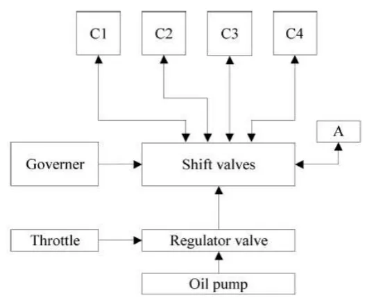
2.1 Hydro-Mechanical Control System
Fig (1) Hydro Mechanical Control System
Figure (1) shows the schematic diagram for the hydro mechanical control system of an early automatic
transmission. The throttle valve mechanically linked to the accelerator pedal determines the system pressure
appropriate to the output torque of an engine. The governor on the output shaft of the transmission moves the
shift valves to apply and release the clutches to change gear appropriately. To avoid the shock during shift,
accumulate or makes some delay of the pressure rising and falling. It has been generally used until 1970s in
most of the automatic transmissions.[1][2][3]
2.2 Electro-Hydraulic Control System
In early 1980s, electronic control units (ECUs) were introduced and rapidly spread over the automotive
industries. It replaced the hydro-mechanical components with the electro-hydraulic ones only for a few years.
This trend made the actuators and the sensors cheaper and cheaper, and changed the system architecture from
the passive to the active with the more advanced actuators and sensors.
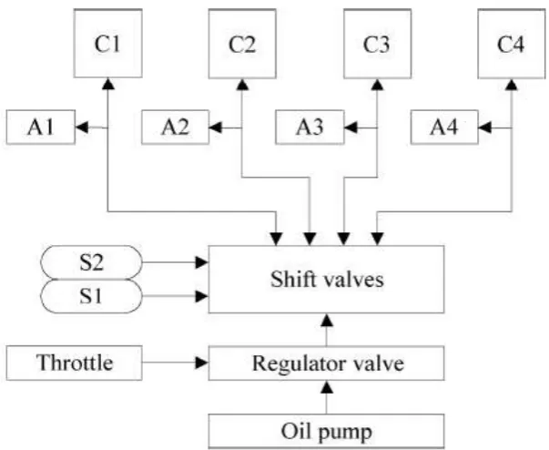
2.2.1 Positive Shift Control
In early 1980s, the first electro-hydraulic control systems were introduced.[4][5] The on-off type solenoid
valves replaced the function of the governor like figure (2). To determine the shift timing, the ECU should
detect the angular velocity of the output shaft. Additionally, accumulators were applied to each friction elements
toachieve optimal shift feeling. We can call this schemepassive shift control because the ECU has only a
9 |
P a g e
Fig (2) Electro-Hydraulic Control System passive Shift Control
2.2.2 Semi Active Shift Control
From mid-80s, more electronic control functions had been applied to the automatic transmissions. An
electronically controlled solenoid valve substituted for the mechanical link to the accelerator pedal. The ECU
read the information such as the throttle opening and the vehicle speed from the various sensors, and determined
the shift timing and controlled the pressure of friction elements to get a better shift feeling.
Fig (3) Electro-Hydraulic Control System semi Active Shift Control
So many variations of this system have been widely used until now from 3-speed to 5-speed. [6][7][8][9][10] In
some of them, the back pressure of the accumulators are controlled by the system pressure according to the
engine torque, but the shifting performance is mainly dependent on the characteristics of accumulators and
orifices yet and the pressure cannot be controlled actively by the ECU. So that, we call the system semi-active.
International Journal of Advanced Technology in Engineering and Science www.ijates.com
Volume No 03, Special Issue No. 01, April 2015 ISSN (online): 2348 – 7550
10 |
P a g e
2.2.3 Active Shift Control
In figure 4, the active shift control scheme is illustrated.[11]The on-off solenoid valves carry out the shift timing
control same as the case of the semi-active, but a pulse width modulation (PWM) solenoid valve or a PCSV
controls the pressure of the friction elements. In most cases, because the solenoid valve outputs only limited
pressure and flow rate, the second stage spool, pressure control valve (PCV),should be used.
This is the mostly advanced scheme in the electro-hydraulic control systems. However, the changing gears in
automatic transmissions needs to control at least 2 friction elements simultaneously. Because there is only one
active actuator, one element has to be controlled by passive hydraulic parts, or an OWC involved for the smooth
shifting.
2.3 Full Electronic Control System
Gott[12] used the terminology, full electronic control, in his book at the first time. In the viewpoint of hydraulic
systems in automatic transmissions, the meaning of full electronic control is that each friction element can be
controlled by the ECU independently. In 1990s, along with the advanced technologies of the electronic control
and sensors and actuators, it is possible to realize this concept with low cost and high reliability.
Fig (4) Electro-Hydraulic Control System – Active Shift Control
11 |
P a g e
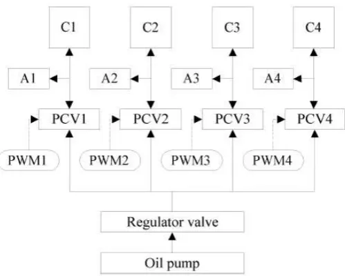
2.3.1 Indirect Semi-Active Shift Control
The active electro-hydraulic control system which consists of a solenoid valve and a second stage spool valve
can be expanded for each friction element. This system, shown in figure (5), offers the maximum degree of
freedom to control the automatic transmission. Some of the manufacturers introduced it in 1990s.[13][14]
This system is good for the clutch-to-clutch shift combined with modern intelligent control algorithms such as
model based robust control. [15] However, the control system of each friction elements consists of many
devices, and as a result it is hard to design the system to satisfy the performance goal. In addition, there are so
many pressure control valves and accumulators in the hydraulic system, so that the cost is high and the size is
large. It may be not a good solution for 5 or more multi-speed automatic transmissions.
Fig (6) Full Electronic Control System – Direct Semi Active Shift Control
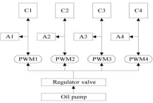
2.3.2 Direct Semi-Active Shift Control
Figure 6 shows the mostly advanced scheme until now, direct semi-active control. It is along the lines of the
indirect concept with more improved actuators. It has a simple circuit, but needs the great performance of the
actuators. The first commercial products with this concept were released in early 1990. [16][17]
They adopted specially designed high capacity PWM solenoid valves as actuators. However, to reduce the
pressure ripples, accumulators were used in each. Additionally, because PWM solenoid valves basically control
the flow rate without any pressure compensation, it is hard to control the system pressure to optimize the fuel
economy without additional sensors. [18]
III. DIRECT ACTIVE SHIFT CONTROL
3.1 Concepts
As mentioned in introductions, it is the main subject of this study to introduce the full electronic control system
for automatic transmissions with proportional control solenoid valves.[19] Figure 7 depicts the new concept,
DASC scheme. For each friction element, only a PCSV is used, that is single stage control system. It has some
advantages as followings:-
The modern control theories can be applied to the full electronic control system with the high degree of
freedom
Simple structure without the second stage spools and accumulators reduces the weight, size, and cost of
the hydraulic system.
International Journal of Advanced Technology in Engineering and Science www.ijates.com
Volume No 03, Special Issue No. 01, April 2015 ISSN (online): 2348 – 7550
12 |
P a g e
Fig (7) Full Electronic Control System – Direct Active Control Scheme
3.2
Type of Actuator
As seen in the previous section, most of the automatic transmissions adopt several electronically controlled
solenoid valves to control the pressure. Two types of them are widely used, the PWM types and the PCSVs. We
choose the PCSV because of the following advantages.
The PCSV can accurately control the pressure proportional to the input current regardless of the
supplying pressure variation.
The PCSV is robust for the environmental disturbances such as oil temperature change.
The PCSV has little pressure ripple and operating noise. Of course, there are some disadvantages.
More complex electrical hardware is required to drive to feedback the current through the PCSV
The PCSV has more complex structure, so that it is weak for contaminated oil
The cost of PCSV is higher than that of the PWM solenoid valve yet
However, hardware of the ECUs and filtration technologies are being greatly improved, and the cost of erased
parts can cancels the increased cost. Therefore, it is sure that this system is the competitive solution in the near
future.
13 |
P a g e
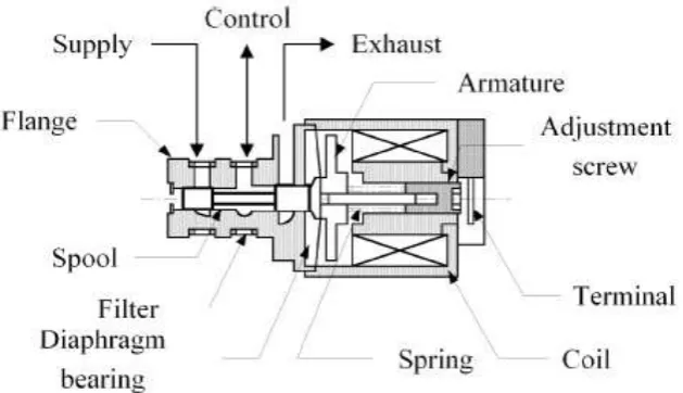
3.3 Performance of Actuator
Figure (8) shows the structure of the PCSV used in this Study.[20] Some characteristics of the PCSV are
following.-
Normally open type solenoid valve : Inverse characteristic between current vs. pressure
Spool type PCSV : Solenoid valve combined with 3- way reducing type spool valve.
Closed loop system : Internal feedback by the difference between pressurized areas of spool lands to
the output pressure
Authors have studied the dynamic characteristics of the solenoid valve in past few years, and figure (9) shows
the results of the PCSV. [21][22][23]
VI. EXPERIMENTS
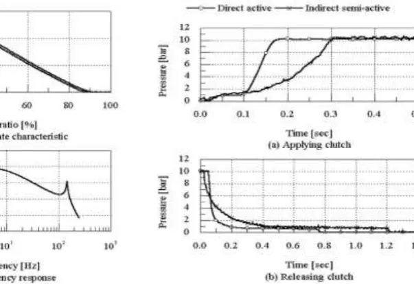
Fig (9) Characteristics of PCSV Fig (10) Comparison of Step Responses
4.1 Comparison of Step Response
To evaluate the DASC system, we chose the available indirect semi-active system that has the clutch-to-clutch shift mechanism. Without any modification of the power train, only the hydraulic systems were switched and the step responses of these systems were compared. The results are shown in figure (10).
The response of the DASC system is faster than that of indirect semi-active system both in applying and releasing. In the semi-active system, the accumulators limit the system response. That is, the accumulators not only reduce the pressure ripple but also decrease the system bandwidth. The initial delay of the DASC may be caused by the electrical circuit to feedback current, and should be improved to achieve the better initial response.[24]
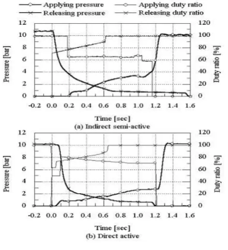
4.2 Open Loop Pressure Control
To compare the system performance totally in the automatic transmission, 1-2 up-shift was performed in the
same condition. At first, pressure profiles of the semi-active system during the up-shift were measured under
certain condition. Then, we tuned the parameters of the DASC system and tested it under the same condition.
International Journal of Advanced Technology in Engineering and Science www.ijates.com
Volume No 03, Special Issue No. 01, April 2015 ISSN (online): 2348 – 7550
14 |
P a g e
Fig (11) Comparison of Upshift
Even though more complex profiles of command duty ratio is required, it is sure that the DASC system works
very well. However, the time lag is quite big in the applying pressure so that the total shift time is slightly longer
than the semiactive system. It may be caused by the small flow rate capacity of the PCSV. As a result, it is
necessary to improve the flow capacity of the PCSV for better performance of the DASC system
V. CONCLUSIONS
Followings are some conclusions of this study:-
This paper reviewed the shift control schemes from the early hydro-mechanical system to modern full
electronic control system. It was certain that the future system needs the simple structure and more degree
of freedom.
The new concept, DASC scheme of full electronic control system using PCSVs was proposed. It is
competitive than any others in the functionality and the reliability with the equal or less cost.
From the experimental results, we can conclude that the DASC system has a reasonable performance but
the initial time delay caused by the electrical circuit and the small flow capacity of the PCSV should be
improved to increase the overall response.
REFERENCES
[1] Akio Numazawa, Seitoku Kubo, Yoshio Shindo, and Shuzo Moroto. 1978. Toyota Four-Speed Automatic
Transmission with Overdrive. SAE 780097.
[2] Dugald Cameron, and Alfred P. Blomquist. 1979. Chrysler's New Front Wheel Drive Automatic
Transmission. SAE 790018.
[3] Erkki A. Koivunen, and Philip A. Le Bar Jr. 1979. Automatic Transmission for Improved Fuel Economy -
General Motors THM 125. SAE 790725.
[4] Yutaka Taga, Kazumasa Nakamura, and Hiroshi Ito. 1982. Toyota Computer Conreolled Four-Speed
15 |
P a g e
[5] Koujiro Kuramochi, Kasuhiko Shindo, Seitoku Kubo, and Masakatsu Miura. 1984. Toyota New
Four-Speed Automatic Transmission for Front Wheel Drive Vehicles. SAE 840049.
[6] Minoru Shinohara, Takashi Shibayama, Kunio Ohtsuka, Katsumi Nawata, Shigeru Ishii, and Hirishi
Yoshizumi. 1989. Nissan Electronically Controlled Four Speed Automatic Transmission. SAE 890530.
[7] Noboru Hattori, Toshikazu Oshidari, Kazuhiro Takadori, Kazuyoshi Iwanaga, Kazuhiko Sugano, and
Figure(11) – Comparison of upshiftSigeto Umebayashi. 1990. A New Five-Speed Nissan Automatic
Transmission for Passenger Cars. SAE 900551.
[8] Tadashi Kondo, Kunihiro Iwatsuki, Yutaka Taga,Takao Tanguchi, and Takuji Taniguchi. 1990.
Toyota"ETC-i" a New Automatic Transmission with IntelligeantElectronic Control System. SAE 900550.
[9] Yasuo Hojo, Kunihiro Iwatsuki, Hidehiro Oba, andKazunori Ishikawa. 1992. Toyota Five-Speed
AutomaticTransmission with Application of Modern Control Theory.SAE 920610.
[10] Stephen R. McKenny, Peter Mack, Steve R. Saia, andSteve Whitney. 1993. General Motors All New
ElectronicTransvers FWD Automatic Transaxle (4T80E), SAE930669.
[11] T.Hiramatsu, and T.Naruse. 1986. Shift QualityControl of an Electronically Controlled Four
SpeedAutomatic Transmission. SAE 865149.
[12] Philip G. Gott. 1991. Changing Gears: TheDevelopment of the Automotive Transmission. Society
ofAutomotive Engineers,Inc.
[13] Katsutoshi Usuki, Kenjiro Fujita, and Katsuhiro Hatta.1996. The INVECS-II Electronically Controlled
AutomaticTransaxles for FWD Passenger Cars. SAE 960429.
[14] Heribert Scherer, and Georg Gierer. 1997. ZF 5-SpeedTransmissions for Passenger Cars. SAE 970689.
[15] Toshimichi Minowa, Tatsuya Ochi, Hiroshi Kuroiwa,and Kang-Zhi Liu. 1999. Smooth Gear Shift
ControlTechnology for Clutch-to-Clutch Shifting. SAETransmission and Driveline systems Symposium.
pp. 263-268
[16] Berthold Martin, and Thomas Nogle. 1989. TheChrysler A-604 Ultradrive 4-Speed Automatic
Transaxle.SAE 890528.
[17] Berthold Martin, and Charles J.Redinger. 1993. 42LEElectronic Four-Speed Automatic Transaxle. SAE
930671.
[18] Berthold Martin, Charles J.Redinger, and HusseinDourra. 1999. Chrysler 45REF : A New Generation
Real-Time Electronic Control RWD Automatic Transmission.SAE Transmission and Driveline systems
Symposium. pp.181-202
[19] Baek-Hyun Cho. 1998. Development of HydraulicSystem for Full Electronically Controlled
AutomaticTransmission. MSc Thesis. Seoul National University(Korean)
[20] Kurt Neuffer, Kurt Engelsdorf, and Werner rehm.1996. Electronic Transmission Control – From
StandaloneComponents to Mechatronic Systems. SAE 960430
[21] Gyu-Hong Jung, Baek-Hyun Cho, and Kyo-Il Lee.1997. Dynamic characteristic Identification of
PWMSolenoid valve for Automatic Transmission. Journal ofKSME(A), Volume 21 No. 10. pp1636-1647
(Korean)
[22] B. H. Cho, G. H. Jung, J. W. Hur, and K. I. Lee. 1998.Dynamic characteristic Identification of
ProportionalControl Solenoid valve for Automatic Transmission. KSAESpring Conference Proceeding,
International Journal of Advanced Technology in Engineering and Science www.ijates.com
Volume No 03, Special Issue No. 01, April 2015 ISSN (online): 2348 – 7550
16 |
P a g e
[23] Baek-Hyun Cho, Gyu-Hong Jung, Jae-Woong Hur, andKyo-Il Lee. 1999. Modeling of Proportional
ControlSolenoid Valve for Automatic Transmission Using SystemIdentification Theory. SAE
Transmission and Drivelinesystems Symposium. pp. 329-335
[24] Hyoun-Woo Lee, Baek-Hyun Cho, and Won-Hi Lee.2000. Modeling and Parameter Optimization of
theProportional Control Solenoid Valve for AutomaticTransmission. FISITA World Automotive