Embedded Design of an Efficient Noise
Canceller for Digital Receivers
AMRITA
ME Student of ECE Department, National Institute of Technical Teachers’ Training & Research, Chandigarh, India
RAJESH MEHRA
Faculty of ECE Department, National Institute of Technical Teachers’ Training & Research, Chandigarh, India
Abstract
This paper presents an error free and area efficient noise canceller for communication receivers. The proposed model has been designed and simulated using Microblaze microcontroller for efficient noise cancellation. The LMS algorithm has been used to design the noise canceller filter. LMS filter alongwtih EDK Processor is presented. The proposed model has been designed and simulated using Simulink and System Generator blocks, synthesized with Xilinx Synthesis tool (XST) and implemented on Virtex4 based xc4vsx35-10ff668 and Spartan 3E based xc3s500e-4fg320 FPGA device. The results show that the output of the EDK processor consisting of Microblaze microcontroller gives error free output. The proposed design on Virtex 4 based xc4vsx35-10ff668 device can operate at the maximum frequency of 82.469 MHz by consuming 1.0139 W power at 37.9°C.A maximum frequency of 49.416 MHz can be achieved on Spartan 3E based xc3s500e-4fg320 target device.
Keywords ANC,ASR,EDK,FPGA,LMS,MAC
1. Introduction
Adaptive Noise Cancelling is a technique within an electronic system to remove the unwanted noise affecting the desired signal. Adaptive Noise Canceller is been applied increasingly in modern communication as it has the advantages of easy implementation and low computational complexity.ANC techniques can also be applied to high frequency signals, multiplexed data coming from an array etc. but in all the high speed applications, a software implementation of ANC usually doesn’t meet the required processing speed unless digital high speed DSP is used with dedicated hardware implementation [1]. Digital signal processors have a wide variety of applications. Now days, it’s becoming increasingly important in our daily life but it imposes the constraints on area, power, speed and cost. So the design has to be carefully chosen. The most commonly used design tools used for hardware implementation are Application Specific Integrated Circuits (ASIC), Digital Signal Processors (DSP) and FPGAs. FPGA can make up the disadvantages of ASIC and DSP as it offers flexibility, time to market and lower system costs [2]. There are two ways to implement LMS algorithm, hardware and software implementation. Hardware implementation of the algorithm in FPGA has good real time stability but requires large resources. The software implementation consumes large amount of resources and also it has low speed which makes its use uncommon [3].
LMS (Least Mean Square) algorithm, which was proposed by Widrow and Hoff, is one of the most widely used adaptive filtering algorithms [4]. A significant feature of LMS algorithm is its simplicity and robustness, good tracking capabilities both in terms of computational load and easiness of implementation. Moreover, it does not require correlation functions, nor does it require matrix inversion. LMS algorithm is a stochastic implementation of the steepest descent algorithm [5].LMS requires only a finite-impulse response filter and a first order weight update equation. Therefore, it has been successfully applied to a wide variety of adaptive filtering problems, including plant identification and noise cancellation applications [6].
efficient adaptive noise canceller is designed which uses LMS algorithm which is implemented on FPGA device.
2. Adaptive Noise Canceller (ANC)
For real time applications, adaptive filter is preferred over other filters. Adaptive filter, as the same suggests, is a self- designing filter. Adaptive filtering relies on the use of noise canceling by subtracting noise from the received signal, an operation controlled in an adaptive manner for the purpose of improved signal-to-noise ratio. With proper provisions filtration and subtraction are controlled by an adaptive process. This filter is used when the complete knowledge of the relevant signal characteristics is not available. The operation of the filter, it relies on recursive algorithm. To initiate the filter operation, the algorithm starts with the initial conditions that are known from the environment. In stationary environment, the algorithm converges to optimum Wiener solution after successive iterations .Whereas in non-stationary environment filter tracks the changes in the weights [8]. So in the real time, stationary or non- stationary environment, the weights of the filter are updated from one iteration to the next. Noise cancellation is the one of the major application area of the adaptive filters .In ANC (Adaptive noise canceller), the adaptive filter cancels the unknown interference contained in the main desired signal. The cancellation is being optimized in some sense [9]. A reference signal is being generated from a sensor which is given as input to the filter. The reference signal supplies the desired signal in such a way that the information-bearing signal component is weak or essentially undetectable. For ANC, we use LMS Algorithm as the update algorithm. This algorithm is simple and effective.
The LMS algorithm is an adaptive algorithm which adjusts the coefficients of filters iteratively. This is done to minimizing the error signal. LMS algorithm consists of two basic processes i.e. filtering process and adaptive process. In filtering process, we compute the output according to the input. We also generate the error by comparing the output and desired response. In adaptive process, according to the error generated the adjustments of the coefficients of the filter take place [10].
3. Proposed Design and Simulation
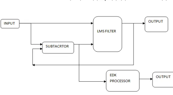
The block diagram of the proposed design is shown in the Figure 1. It consists of the LMS adaptive filter and an EDK based processor. The input to the model is the noise signal. This signal acts an input to the LMS adaptive filter. The other input to this filter is the error signal. LMS filter output y (n) as shown in Eq1 is product of the tap-input vector x(n) and weight at a particular iteration w(n).
y(n)=w(n)x(n) (1)
At the end of each iteration, the error signal e(n) is calculated. The error signal is the difference between the desired response d(n) and the output of the filter y(n) as shown in Eq.2.
e(n)=d(n)-y(n) (2)
Once the error signal is calculated. The weights of the LMS filter are upgraded according to Eq.3. The new upgraded weight w(n+1) depends on the error signal e(n), input signal x(n), step size µ and the weight of last iteration w(n).
w (n+1) = w(n) + µx(n)e(n) (3)
The LMS filter uses 32 tap MAC filter along with the LMS algorithm. This filter is made using Simulink and Xilinx System Generator .This algorithm is very simple and effective. The LMS adaptive filter contains Dual port RAM. Dual port means that this RAM contains two ports namely A and B. Each port can individually perform the read/write operation. Read and write operation can be simultaneously done at two different ports .An Addressable shift register (ASR) is used to provide addresses to the noisy signal. The noisy signal is multiplied by the error to generate a new signal. This new signal is now compared with the weight of last iteration to get the new updated weight. New upgraded weights are stored in the RAM and used by the MAC Filter. In this way, on each iteration the weights are updated and the error is reduced.
Figure 2: LMS Filter
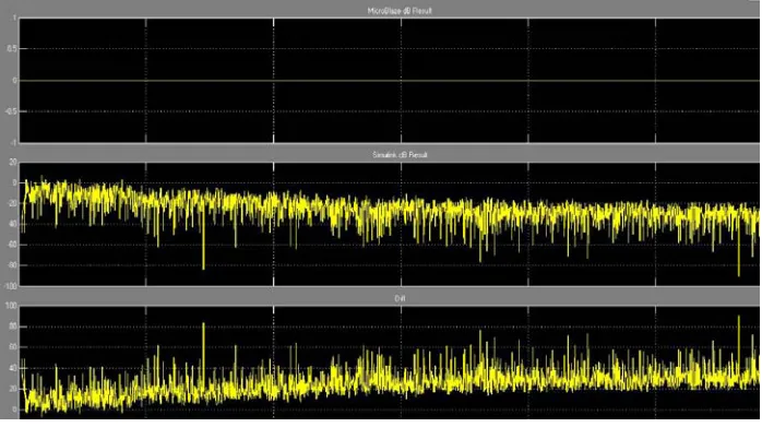
In the other part of the model, Xilinx’s EDK(embedded development kit) which is the development package for building Microblaze embedded processor systems in Xilinx FPGAs is used. The environment used for EDK is XPS (Xilinx Platform Studio)[11]. The error so generated by the LMS filter is used by the Microblaze Microcontroller for further reduction of the error.
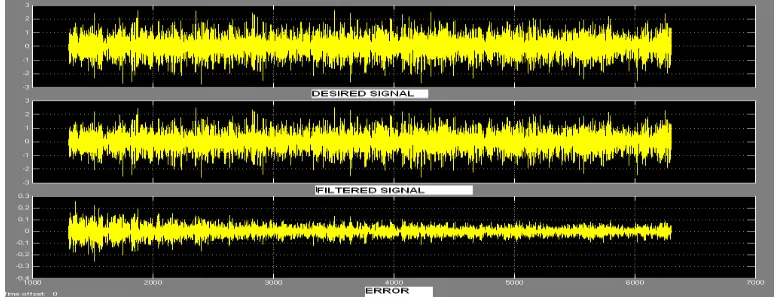
The proposed model has been designed and simulated using Simulink and Xilinx Generator blocksets. EDK along with Microblaze is also used. The simulated results are seen in the form of waveforms which are the outputs from the scope. The output of the LMS filter which consists of three signals is shown in figure 3. The first signal is the desired signal, the second signal is the output from LMS filter and the third signal is the error between the above two signals. The noise from the desired signal is reduced on successive iterations but is never zero.
Fig 3: Output waveforms from LMS filter
Fig 4: Output from EDK Processor
The frequency response of the LMS filter is shown in Figure 5. The LMS filter used here is a High pass adaptive filter which has with following specifications:
.Fs=48000 Hz, fstop=9600 Hz, fpass =12000Hz .
Fig 5 : Frequency response
The filter used in the proposed model is the MAC filter. The coefficients of the filter are updated from one iteration to the next. Figure 6 shows the position and exact values of all 32 coefficients of the adaptive filter.
Fig 6: Filter taps
4. Hardware Implementation Results
Table 1 Device Utilization Based on Virtex4 and Spartan 3E FPGA
Device utilization summary
Description Used/Available( Utilization)
Virtex 4 Spartan 3E
Number of Slice 2142/15360 (13%) 1950/4656(41%)
Number of Slice Flip Flops 1821/30720(5%) 1821/9312(19%)
Number of 4input LUTs 3381/30720(11%) 3382/9312(36%)
Number of bonded IOBs 167/448 (37%) 167/232(71%)
Number of GCLKs 2/32(6%) 2/24(8%)
Speed ( MHz) 82.469 49.416
The proposed design implemented on Spartan 3E based FPGA can work at maximum operating frequency of 49.416 MHz. And when the proposed design is implemented on Virtex 4 based FPGA it can work at maximum operating frequency of 82.469 MHz.
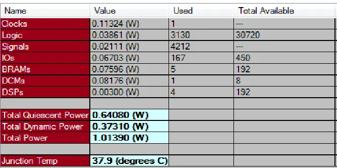
The total power consumption of the proposed design based on xc4vsx35-10ff668 FPGA device has been calculated using XPower utility. It can be observed from the table 2 that proposed design has consumed 1.01W at 37.9° C.
Table 2 Power Consumption
Finally the proposed design results based on Virtex4 and Spartan 3E FPGA have been compared with [1]. The proposed design has shown an improvement in table 3 by consuming less number of slices available on target FPGA
Table 3: Result comparison
Description Standard LMS Modified LMS[1] Proposed model
Spartan 3 E Virtex 4
Number of slices used 2750/3072 1176/3072 1950/4656 2142/15360
Clock frequency (MHz)
25 50 49.4 82.47
Error signal (db)
40 36 0 0
5. Conclusion
In this paper, Microblaze microcontroller based efficient noise canceller has been designed and simulated. The proposed design has been implemented using optimized LMS algorithm. The MAC unit and DUAL PORT RAM has been utilized for enhancing the speed of the overall design by reducing the error to zero. The direct form II architecture has been used for the filter which provides improved area efficiency. The proposed design can provide a speed of 82.469 MHz with Virtex 4 device and 49.416 MHz with Spartan 3E device by consuming considerably less resources in terms of slices to provide cost effective solution for wireless communication applications.
Acknowledgement
I would like to thank the Almighty, who has guided me to work on the right path of the life. This work would not have been possible without the encouragement and able guidance of my guide Mr. Rajesh Mehra, Assistant Professor, Department of Electronics and Communication Engineering, NITTTR, Chandigarh. Most of the novel ideas and solutions found in this research work are the result of his numerous stimulating discussions. References
[1] Di Stefano A.; Scaglione, A.; Giaconia C.;Efficient FPGA implementation of an adaptive noise canceller, Computer Architecture for Machine Perception, 2005. CAMP 2005. Proceedings. Seventh International Workshop on Digital Object Identifier: 10.1109/CAMP.2005.22 Publication Year: 2005 , Page(s): 87 - 89
[2] Tian Lan; Jinlin Zhang; FPGA Implementation of an Adaptive Noise Canceller, Information Processing (ISIP), 2008 International Symposiums on 23-25 May 2008 Page(s):553 - 558
[3] P. Waldeck and N. Bergmann, Evaluating software and hardware implementations of signal-processing tasks in an FPGA,” in Proc. EEE International Conference on Field-Programmable Technology, Brisbane, Australia, Dec. 2004, pp. 299-302.
[4] B. Widrow, J. R. Glover, J. M. McCool, J. Kaunitz, C.S. Williams, R. H. Hearn, J. R. Zeidler, E. Dong and R. C. Goodlin, “Adaptive noise canceling: Principles and applications”, Proc. IEEE, vol. 63, Dec. 1975, pp.1692-1716.
[5] Zheng-wei Hu; Zhi-yuan Xie; Modification of Theoretical Fixed-point LMS Algorithm for Implementation in Hardware, Electronic Commerce and Security, 2009. ISECS '09. Second International Symposium on Volume: 2 Digital Object Identifier: 10.1109/ISECS.2009.40 Publication Year: 2009 , Page(s): 174 – 178
[6] Boo-Shik Ryu; Jae-Kyun Lee; Joonwan Kim; Chae-Wook Lee; The Performance of an adaptive noise canceller with DSP processor ,System Theory, 2008. SSST 2008. 40th Southeastern Symposium on 16-18 March 2008 Page(s):42 – 45
[7] Microblaze processor, www.xilinx.com/microblaze. [8] S. Haykin, Adaptive Filter Theory, Prentice-Hall,third edition
[9] Hongyan Cui; Chongfei Shen; Xiaobo Xie; Yong Hu; Luk, Study on Adaptive Noise Canceller Based onFixed-Point Algorithm for Real-Time Somatosensory Evoked Potential Monitoring K.D.; Bioinformatics and Biomedical Engineering, 2008. ICBBE 2008. The 2nd International Conference on Digital Object Identifier: 10.1109/ICBBE.2008.884 Publication Year: 2008 , Page(s): 2213 – 2216 [10] A. Elhossini, S. Areibi and R. Dony, “An FPGA Implementation of the LMS Adaptive Filter for Audio Processing,” in Proc. IEEE
International Conference on Reconfigurable Computing and FPGAs, Sept. 2006, pp.1-8.
[11] WaldeckP.;Bergmann,N.; Evaluating software and hardware implementations of signal processing tasks in an FPGA, Field-Programmable Technology, 2004. Proceedings. 2004 IEEE International Conference on Digital Object Identifier: 10.1109/FPT.2004.1393284 Publication Year: 2004 , Page(s): 299 - 302
Authors
Amrita: Ms.Amrita is currently pursuing M.E. degree from National Institute of Technical Teachers’ Training and Research, Chandigarh. She has completed B.Tech degree in Electronics and Communication from PTU, Jalandhar, Punjab, in 2007. Ms. Amrita has authored a paper in national conference. Ms.Amrita’s interest areas are VLSI design and Embedded System design