DEVELOPMENT OF DIRECT TORQUE
CONTROL MODELWITH USING SVI
FOR THREE PHASE INDUCTION
MOTOR
MUKESH KUMAR ARYA*
Electrical Engg. Department, Madhav Institute of Technology & Science, Gwalior, Gwalior, 474005, India†
DR. SULOCHANA WADHWANI
Electrical Engg. Department, Madhav Institute of Technology & Science, Gwalior, Gwalior, 474005, India
Abstract:
Direct torque control method is one of the best control strategies which allow a torque control in steady state and transient operation of induction motor. The main aim of direct torque control strategies is to effectively control the torque and flux of induction motor. Direct torque control method made the motor more accurate and fast torque control, high dynamic speed response and simple to control. This paper present the principle of the direct torque control for voltage source inverter fed induction motor drive, and switching table, amplitude selection of the hysterics band of torque and flux. And also this method based on space vector modulation and it’s considered as an alternative to field oriented control technique. Direct torque control methods are the first technology to control the ‘real’ motor control variable of torque and flux. And it has also more advantage such as it not required a feedback device and also not need external excitation. The performance of direct torque control method has been demonstrated by simulation using a simulation package in matlab.
Keywords: direct torque control; space vector modulation; induction motor.
1. Introduction
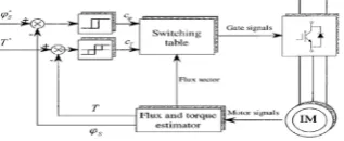
component such as torque and flux hysteresis controller, torque and flux estimator and a switching table etc. as shown in Fig. 1.
Fig. 1. Block diagram of direct torque control technique
2. Basic concept of direct torque control
In direct torque control method the stator flux and stator torque directly controlled by selecting the appropriate inverter switching state. And stator current and voltage are indirectly controlled hence no current feedback loop are required. As shown in block diagram of direct torque control scheme it’s including two hysteresis controllers. In the stator flux controller that imposes the time duration of active voltage vectors, which rotates the stator flux along with the reference trajectory and in the stator torque controller that determine the time duration of zero voltage vector which keep the motor torque in the predefine hysteresis tolerance band. At each sampling time the voltage vector selection block choose the inverter switching state (Sa,Sb,Sc) which reduces the
flux and torque errors. Hence the inverter fed induction machine develop torque is carried out by hysteresis controller that select one of the six non-zero and two zero inverter voltage vector as shown in Fig 2. and this selection are made in order to maintain the torque and flux error inside the hysteresis band in which the error is indicate by ΔTe and ΔΨs. as given
ΔTe= Teref − Te (1)
Δψs
s= ψssref − ψss (2)
The six different state of Vss considering Vi(i=1-6) noted as Sa,Sb,Sc as the switches status of inverter are
shown in Fig. 2.
Fig.2. PWM VSI inverter eight switching states and corresponding switching space vectors The upper switching states can be defined as the equation given below.
Vas = 2Sa-Sb-Sc Vdc (3)
3
Vbs = Sa+2Sb-ScVdc (4)
3
Vcs = -Sa-Sb+Sc Vdc (5)
3 Hence, the space vector is
Vss = 2 Vdc (Sa+Sbej2π/3 +Scej4π/3) (6)
3
3. Torque control
The electromagnetic torque of induction machine is as cross product of the stator and rotor flux vector or stator current and flux as given by Eq.(7) is a sinusoidal function of γ and the angle between Ψs
s and Ψrr are shown in
Fig.3. Stator and rotor flux space vector
Te = 3 P Is*j Ψs
2 (7)
The magnitude of electromagnetic torque is written as Te = 3 P Lm Ψss Ψrr sin γ (8)
2 2 Ls Hence by selecting appropriate inverter voltage vectors Vi to obtain strong rotation speed of Ws a good dynamic performance can be achieved. The actual stator flux can be estimated from the equivalent circuit of the motor as follows: Ψs s = ∫ (Vss – RS.iss) ∂t (9)
Where Vss and iss , are stator voltage and current respectively The Electromagnetic torque of the motor is calculated by the equation. Te = 3 P ( Ψsds isqs – Ψsqs isds) (10)
2
4. Stator control For control the stator flux, selecting the appropriate inverter output voltage Vi(i=1-6), the stator flux Ψss rotates at the desired frequency Ws inside the specified band. If stator ohmic drops are neglected, the stator voltage impressed directly the stator flux in accordance with the equation. Vss = d Ψss (11)
dt Or dΨs s = Vss dt (12)
Therefore during the time interval of Δt, the variation of the stator flux space vector due to the application of stator voltage vector Vs can be approximated as in equation ΔΨs s = VssΔt. (13)
5. Modeling of induction motor One of the major differences between FOC and DTC control is the modeling of the motor. In FOC the motor is modeled in synchronously reference frame i.e. ω = ωe, while in DTC it is in stationary reference frame i.e. ω = 0. The basic mathematical model of the induction machine is derived from the Fig. 4 and is rewritten as below: FIG. 4: Equivalent Induction Machine circuit at dq reference frame. Vqs = RS iqs + ω.λds + ∂λqs/∂t (14)
Vqr = Rriqr + (ω – ωr)λdr + ∂λqr/∂t (15)
Vds = RSiqs – ω λqs + ∂λds/∂t (16)
Vqr = Rridr – (ω – ωr)λqr + ∂λdr/∂t (17)
6. Basic Switching Table and Selection of Voltage Vectors
The basic working principle of switching table of direct torque control concept is shown in Fig. 1. The reference stator flux Ψsref , and torque Teref are compared with the actual value of Ψs, and Te in hysteresis flux and torque
controller respectively. The hysteresis flux controller is a two-level comparator while the hysteresis torque controller is a three-level comparator.
The output signal of hysteresis flux controller is define as given below
Ψserr = 1, for Ψs < Ψsref – HΨ (19)
Ψserr = -1, for Ψs < Ψsref +HΨ (20)
And output signal of hysteresis torque controller are define as given below
Teer = 1, for Te<Teref – Hm (21)
Teerr = 0, for Te = Teref (22)
Teerr = -1, for Te<Teref +Hm (23)
Where 2HΨ is the flux tolerance band and 2 H m is the torque tolerance band.
On the basis of the torque and flux hysteresis status and stator flux switching sector which is indicated by α = ⁄ Ψs
s. = tan-1(Ψsqs / Ψsds) (24)
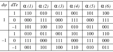
Switching table output is a setting of switching devices of the inverter; hence direct torque control technique selects the inverter voltage vector to apply the induction machine from table1.
Fig.5. show the relationship between the inverter voltage vector and stator flux switching sector in which six active switching vectors are:
V1=(1,0,0), V2=(1,1,0), V3=(0,1,0), V4=(0,1,1), V5=(0,0,1), V6=(1,0,1)
And two zero switching vectors are: V0=(0,0,0), V7=(1,1,1)
And also
-30o<α(1)<30o 30o<α(2)<90o 90o<α(3)<150o 150o<α(4)<210o 210o<α(5)<270o 270o<α(6)<330o
Fig. 5. Stator and rotor flux space vector
Table 1. Switching table of inverter voltage vectors
7. Simulation Implementation and result
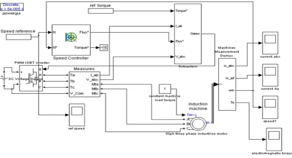
The direct torque control principle has been simulated using Matlab/Simulink . The simulink model of the direct torque control scheme fed from IGBT PWM voltage source inverter for the three phase induction motor rated 10Hp (7.5KW) 400v , 50hz and 1440 rpm are shown in Fig. 6. The dynamics performance of load torque produce by direct torque control model is evaluated by applying a variable load torque commend on the torque reference points maintained to amplitude of 25 Nm after 0.04ms. And the mechanical dynamics torque commends is maintained to 1 Nm. And speed reference is also applied to speed reference command point. The simulation time used in this simulation is adjusted to 0.1ms.
The main features of direct torque control can be summarized as follows: • DTC is completely a motion-sensor less control method.
• DTC is not sensitive for rotor parameters because its need only stator flux and torque estimator.
dψ dTe α (1) α (2) α (3) α (4) α (5) α (6)
1
1 110 010 011 001 101 100 0 000 111 000 111 000 111 –1 101 100 110 010 011 001
–1
Fig. 6. matlab simulink model for direct torque control
Fig. 7. Electromagnetic torque response Fig. 8. Speed responce
Fig. 9. Stator phase current response Fig. 10. Stator phase trajectory
8. Discussion and conclusion
Acknowledgments
I would like to thank firstly my guide Dr. S. wadhwani, electrical department for his patience, care and guidance given to me throughout the duration of my work. Then, I would like to dedicate this to my parents who support everything to me.
References
[1] M. Depenbrock, “Direct self control of inverter fed induction machines,” IEEE Trans. Power Electron., vol. 3, pp. 420-429, Oct 1988. [2] F. Blaschke, “The principle of field-orientation as applied to the transvector closed-loop control system for rotating—field
machines,”SIEMENS Rev. Vol. 34, pp. 217-220, 1972. [3] P.C. Krause, “Analysis of Electrical Machinery”.
[4] Mohammed H. Rashid, “Power Electronics”, PEARSON Education
[5] B. K. Bose, Modern Power Electronics and AC Drives. Englewood Cliffs, NJ: Prentice-Hall, 2001.
[6] N. R. N. Idris, and A.H.M. Yatim, “ Direct Torque controlof Induction machines with constant switching frequency [7] Vas, P., 1990. Vector Control of a.c.machines.Oxford University Press.
Appendix
The test machine is a three phase and 50hz induction machine having the following parameter.
RS = 0.7384 ohm.
Rr = 0.7402 ohm.
LS = 0.003045 Henry.
Lr = 0.003045 Henry.
Lm = 0.1241 Henry.
P = Number of Poles = 2.
J = Moment of Inertia = 0.14.
B = Friction Coefficient = 0.0.