© 2016 IJSRSET | Volume 2 | Issue 3 | Print ISSN : 2395-1990 | Online ISSN : 2394-4099 Themed Section: Engineering and Technology
Modeling & Simulation of Permanent Magnet Synchronous
Wind Generator Based Stand-alone System
Smitkumar S. Tandel
1, Jay S. Tandel
2, Krishnakant D. Tandel
3 1P.G. Student, Department of Electrical Engineering, MGITER, Navsari, Gujarat, India 2Assistant Professor, Department of Electrical Engineering, MGITER, Navsari, Gujarat, India 3
P.G. Student, Department of Electrical Engineering, L. D. Collage of Engineering, Ahmedabad, Gujarat, India
ABSTRACT
This paper uses a suitable power converter topology for a Wind Energy Conversion system with Permanent Magnet Synchronous Generator (PMSG) for stand-alone operations. The present work presents the system in which a PMSG feeds an isolated load through a closed loop boost converter. The output voltage and frequency of the PMSG is variable in nature due to non-uniform wind velocities. The variable ac output is rectified by a diode rectifier and maintained constant by a boost converter. The boost converter is provided with a closed loop feedback control, which is designed using PID controller. In this controller the output voltage is continuously sensed and duty ratio of the switch is varied to maintain the DC link voltage constant. The converter output is fed to three phase inverter which employs a sine PWM technique, the output of which is fed to the load. The power converters and together with independent control systems can effectively improve the output voltage and frequency of the wind PMSG feeding an isolated load. The whole system is simulated using MATLAB/ Simulink and the results are presented to demonstrate the veracity of the developed control scheme.
Keywords : Permanent Magnet synchronous Generator (PMSG), Closed loop boost converter, Three phase inverter, Three phase diode bridge rectifier.
I.
INTRODUCTION
Recent trend indicates that wind energy will play a major role to meet the future energy target worldwide to reduce reliance on fossil fuel and to minimize the adverse impact of climate change. Wind energy is the fastest growing generation technology among the renewable energy sources. Over the last decade, the global wind energy capacity has increased rapidly and wind is an important competitor to the traditional sources of energy. In 2013, more than 35 GW of wind power capacity was added to the global wind generation capacity which became 318 GW. Since 2008, annual growth rates of cumulative wind power capacity have averaged 21.4%, and global capacity has increased eightfold over the past decade [9].
The small scale wind energy conversion systems are more efficient and cost effective. Among AC type generation systems, those based on Permanent magnet
increased attention because of its operation at high power factor, high efficiency and increased reliability due to its self-excitation property Three-phase six switch rectifier is of wide interest to be used as generator side converter [1].
Stand-alone system power system is also known as remote area power supply is an off-the grid electricity system for locations that are not fitted with an electricity distribution system. Typical stand-alone power system include one or more methods of electricity generation, energy storage and regulation. The electricity is typically generated by following methods:
1. Photovoltaic system using solar panels 2. Wind turbine
3. Geothermal source
4. Diesel or bio-fuel generation 5. Micro hydro generation [2].
Stand-alone (off-grid) power system (SAPS) is the small-scale power system which is suitable for the rural (remote) areas where grid connectivity is not possible and/or where independent power supply is needed [2].
II.
BLOCK DIAGRAM OF THE SYSTEM
The wind turbine is the prime mover of the Permanent magnet synchronous generator. As the wind velocity is non-uniform in nature, the output of PMSG will be fluctuating. Therefore it cannot be interfaced directly to the load. The output of PMSG is converted to DC using a full bridge rectifier and the variable DC is converted to constant DC by a closed loop Boost converter. This constant DC output is converted to AC using an inverter. This inverter is operated with Sine PWM technique and fed to the load [1].
Figure 1. Basic Block Diagram of PMSG Based Stand-alone System [1].
A. Permanent Magnet Synchronous Generator
The Permanent magnet synchronous generators are
being used in many small generating systems,
particularly wind power system. The PMSG is
typically constructed with magnets attached to the
rotor and a three phase winding in the stator core. It
is particularly an attractive option in renewable
energy applications, because it has high conversion
efficiency. It is of simple design, robust and reliable.
PMSG do not require an additional DC supply for
the excitation circuit.
According to the flux direction permanent magnet,
generators can be classified as radial, axial &
transversal flux machine [1].
B. Three Phase Diode Rectifier
Figure 2. Three Phase Diode Rectifier [1].
The diode rectifier is the most simple, cheap, and rugged topology used in power electronic applications. The most disadvantage of this diode rectifier is its disability to work in bi-directional power flow. The variable output dc voltage from three-phase diode bridge rectifier can be obtained[1].
C. Boost Converter
Figure 3. Basic Schematic Diagram of Boost Converter [1].
A boost converter is sometimes called a step-up converter since it “steps up” the source voltage. The output voltage of the boost converter is given by
= ( )
Where,
Vin = input voltage of boost converter Vo = output voltage of boost converter D = duty cycle [1].
D.Closed Loop Control of Boost Converter
The closed system of boost converter is obtained by using a Voltage mode PWM Scheme. The block diagram of which is shown in the figure 3.8. In this technique the output of the boost converter is kept constant by using the duty ratio as the control variable [1].
Figure 4. Closed Loop Boost Converter [1]
The error amplifier compares the output voltage Vo with the reference voltage and generates the error signal. This error signal is given as the input to the PI controller. The
output of the PI controller is compared with the saw-tooth signal and the pulses are generated. The output pulses are functions of duty cycle [1].
The boost converter operate in Continuous conduction mode for L > Lb, where
= ( )
.
The value of the filter capacitor required is more to limit the output voltage ripple. The minimum value of filter capacitor needed is given by
=
Where,
D is the duty ratio
f is the switching frequency R is the load resistor is the ripple voltage [1].
E Three Phase Inverter
An inverter is a circuit that converts DC to AC. Pulse Width Modulation (PWM) is a switching technique that is used to decrease the total harmonic distortion in the inverter circuit. The output of the boost converter is fed to a three phase inverter which converts the constant DC to constant AC having a frequency of 50 Hz. The schematic diagram of a three phase inverter is shown in the fig. 5 [1].
Figure 5. Three Phase Inverter [1]
constant input voltage Vo. To obtain balanced three-phase output voltages in a three-three-phase PWM inverter, the triangular voltage waveform is compared with three sinusoidal control voltages that are 120 deg out of phase [1].
III. SIMULATIONS & RESULTS
The simulation result of the proposed work in open
loop and in closed loop is discussed for the
variations in the PMSG speed and for variations of
wind speed.
A.Open Loop Simulation
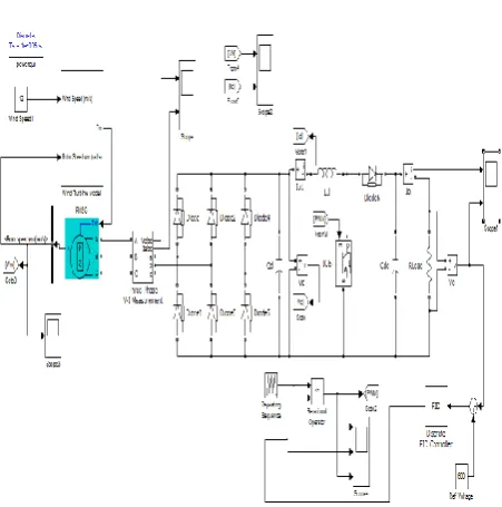
The simulation model of PMSG with Boost converter for open loop mode is shown in fig.6
Figure 6. Open Loop Simulation of PMSG with Boost Converter.
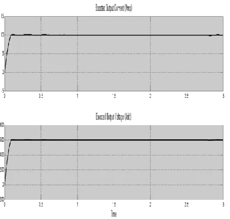
Figure 7. Waveform of Boost Converter Output voltage & Current at wind speed 12 m/s.
Figure 8. Waveform of Boost Converter Output voltage & Current at wind speed 16 m/s.
Figure 9. Waveform of Boost Converter Output voltage & Current at wind speed 8 m/s.
B. Closed Loop Simulation
Figure. 11 Waveform of Boost Converter Output voltage & Current at wind speed 12 m/s.
Figure 12. Waveform of Boost Converter Output voltage & Current at wind speed 16 m/s.
Figure 13. Waveform of Boost Converter Output voltage & Current at wind speed 8 m/s.
IV. CONCLUSION
In this paper, the power electronic topology comprising of diode rectifier, DC to DC boost converter and inverter for a variable wind energy conversion system with PMSG for a standalone application is presented. The state space averaging technique employed for obtaining transfer function of the boost converter and the subsequent design of PID controller using trial & error technique for the dc-dc boost converter for maintaining the required dc link voltage constant is given in detail. The analysis and dynamic response with the designed controller is carried out for varying wind speed and load and the simulation results are given to validate the design. Further investigations are carried out for obtaining the range of wind speed and load variation that the designed controller can work in isolated mode with regulated voltage at the load is presented.
V.
ACKNOWLEDGMENT
The parameters of wind turbine & PMSG are given by table I.
TABLE I.
PARAMETERS OF WINDD TURBINE & PMSG
Wind turbine
Density of air 1.225 Kg/m3
Area swept by blades, A 1.06 m2 Optimum coefficient,
Kopt
1.67 Nm/(rad/s)2
Base wind speed 12 m/s
PMSG
No. of poles 10
Rated speed 153 rad/sec
Rated current 12 A
Armature resistance, Rs 0.425 Magnet flux linkage 0.433 Wb Stator inductance, Ls 8.4 mH
Rated torque 40 Nm
VI. REFERENCES
[1] G.Vijayalakshmi and M.Arutchelvi, “Design and
Development of Controller for PMSG based Wind
Energy Conversion System,” International
Conference on Circuit, Power and Computing Technologies, 2014.
[2] M. E. Haque, K. M. Muttaqi, and M. Negnevitsky,
“ Control of a stand-alone variable speed wind turbine with a permanent magnet synchronous generator,” IEEE Transactions on Industry Applications, Vol. 46, no. 1, January/February 2010.
[3] Rajveer mittal, K.S.Sandhu and D.K.Jain, “ An
overview of some important issues related to wind energy conversion system (WECS),” International journal of environmental science and development, Vol. 1, no. 4, ISSN: 2010-0264, October 2010.
[4] Rajib Datta and V. T. Ranganathan, “ A Method of
tracking the peak power points for a variable speed
wind energy conversion system,” IEEE
Transactions on Energy Conversion, Vol. 18, no. 1, March 2003
[5] C. N. Bhende, S. Mishra and Siva Ganesh Malla, “
Permanent Magnet Synchronous Generator-Based Standalone Wind Energy Supply System,” IEEE Transactions on Sustainable Energy, Vol. 2, No. 4, October 2011.
[6] Neeraj Pareta & Naveen Sen, “ Modelling and
Simulation of Permanent Magnet Synchronous Motoer Based Wind Energy Conversion System,” International Journal of Emerging Research in Management & Technology,Volume-3, Issue-7, July 2014.
[7] Yi lay Nge, Zaw Min Naing, Kyaw Soe Lwin,
Maung Maung Latt, “ Design Implementation of Boost Converter for Variable Speed Small Wind Turbine,” international journal of scientific engineering & technology research, ISSN 2319-8885 Vol.03,Issue.15 July-2014.
[8] K. Prechanon, “Mathematical Model of the PMSG
based on Wind Energy Conversion System,” International Research Journal of Innovative Engineering, Volume1, Issue 3, March 2015.
[9] Mujaddid Morshed Chowdhury, “Modelling and
Control of Direct Drive Variable Speed Wind
Turbine with Interior Permanent Magnet
Synchronous Generator,” University of Tasmania, June 2014.
[10] Mahmoud M. Hussein, Tomonobu Senjyu,
![Figure 2. Three Phase Diode Rectifier [1].](https://thumb-us.123doks.com/thumbv2/123dok_us/1177469.1620393/2.595.40.286.607.742/figure-three-phase-diode-rectifier.webp)
![Figure 3. Basic Schematic Diagram of Boost Converter [1].](https://thumb-us.123doks.com/thumbv2/123dok_us/1177469.1620393/3.595.55.276.50.161/figure-basic-schematic-diagram-boost-converter.webp)