390 |
P a g e
FORGING DEFECTS ANALYSIS IN AXLE SHAFT
USING TAGUCHI METHOD
1
Vipan Chand,
2Dr.S.S.Sen,
3Aman Kishore Sharma
1PG Student Mech. Engg. Deptt. G.H.E.C Solan.( India)
2
Principal G.H.E.C Solan.( India)
3
PG Student Mech. Engg. Deptt. NITTTR Chandigarh.( India)
ABSTRACT
Forging process commonly used in industry and affected by the process temperature. A study has been conducted
to understand the effect of forging process parameters of the axle shaft. The axle shaft is made of different
material. The four significant parameters such as billet weight, billet temperature, forging time and the die
temperature were used to optimize and reduce the rejections due to various forging defects. Forging defects of
axle shaft under different manufacturing conditions successfully analyzed using Taguchi’s experimental design method. Taguchi’s method provides a simple, systematic and efficient methodology for the optimization of the
control factors. Forging time is the most significant factor followed by weight of billet and initial die temperature
while the forging temperature has the least or almost no significance on defects of the forged gear whereas,
forging temperature is the most significant factor followed by weight of billet and initial die temperature while the
forging time has the least or almost no significance on defects of the forged axle shaft.
Keywords: Axle shaft, billet temperature, Forging temperature.
I. INTRODUCTION
Forging is a manufacturing process where metal is pressed, pounded or squeezed under great pressure into high
strength parts known as forgings. The process is normally (but not always) performed hot by preheating the metal
to a desired temperature before it is worked. The forging process can create parts that are stronger than those
manufactured by any other metalworking process. This is why forgings are almost always used where reliability
and human safety are critical. The Figure 1.2 shows the various processes at the different location point such as
the die, die and work interface, plastic deformation etc.
Forging process set up
The forging set up consist of the various operation such as shearing/cutting of the billet to the proper weight as
provided in standard operating procedure (SOP), heating of the billet in an controlled environment to the forging
391 |
P a g e
heat treatment, cleaning and inspection as per laid down procedure in SOP. The sub systems used are:
Raw material identification and inspection Gear billet cutting process
Gear billet heating process Forging die
Forging hammers Heat treatment process Cleaning process
II. EXPERIMENTAL METHODOLOGY
2.1 Introduction
This chapter presents the detailed description of the raw materials and methodology used in this research work.
The forging defects are generally characterized by weight of the billet, billet temperature, time during forging,
friction and initial temperature of die. In this work, the forging defects of axle shaft studied. Parts under study in a
lot size of 150 parts in each lot, then parts are inspected for forging defects as per standard operating procedure
(SOP) and the rejection in each set of trail is recorded for statistical analysis. The process parameters under
different combinations are selected and applied during the actual forgings of the parts.
2.2 Research Outline
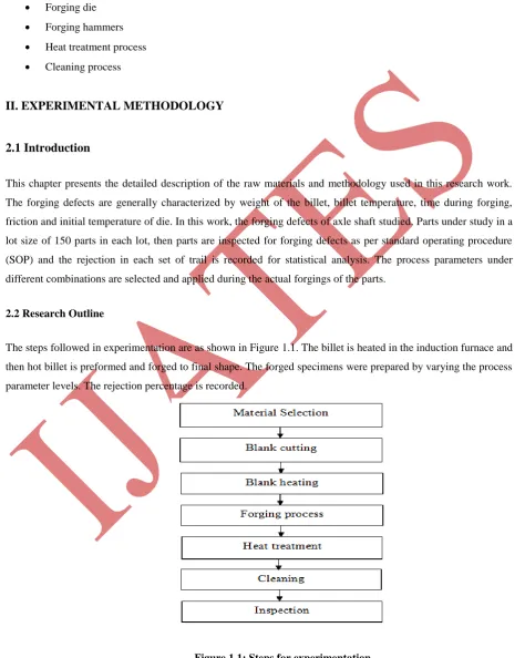
The steps followed in experimentation are as shown in Figure 1.1. The billet is heated in the induction furnace and
then hot billet is preformed and forged to final shape. The forged specimens were prepared by varying the process
parameter levels. The rejection percentage is recorded.
Figure 1.1: Steps for experimentation.
392 |
P a g e
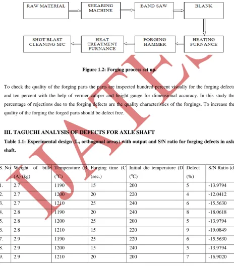
The schematic diagram of experimental setup is shown in the Figure 1.2 .The billet from the raw material rod was
first cut by the shearing machine and then cut to the final size and weight by the band saw. The billet is the heated
in the induction furnace up to the forging temperature. The hot billet is then placed on the blocker die to remove
the scaling and make the pre-form; the pre-form is then placed on the finish die to make the forging of the desired
shape and size. The hot forging is the cooled and heat treated to relieve the stresses induced during forging. The
oil fired heat treatment furnaces are used for annealing and normalizing. The forged components are the cleaned
by the shot blast cleaning machine by using the metal ball blast and the air blast.
Figure 1.2: Forging process set up.
To check the quality of the forging parts the parts are inspected hundred percent visually for the forging defects
and ten percent with the help of vernier caliper and height gauge for dimensional accuracy. In this study the
percentage of rejections due to the forging defects are the quality characteristics of the forgings. To increase the
quality of the forging the forged parts should be defect free.
III. TAGUCHI ANALYSIS OF DEFECTS FOR AXLE SHAFT
Table 1.1: Experimental design (L9 orthogonal array) with output and S/N ratio for forging defects in axle
shaft.
S. No. Weight of billet
(A) (kg)
Temperature (B)
(oC)
Forging time (C)
(sec.)
Initial die temperature (D)
(oC)
Defect
(%)
S/N Ratio (db)
1. 2.7 1190 15 200 5 -13.9794
2. 2.7 1200 20 220 4 -12.0412
3. 2.7 1210 25 240 6 -15.5630
4. 2.8 1190 20 240 8 -18.0618
5. 2.8 1200 25 200 5 -13.9794
6. 2.8 1210 15 220 9 -19.0849
7. 2.9 1190 25 220 6 -15.5630
8. 2.9 1200 15 240 5 -13.9794
393 |
P a g e
The experimental results were also analyzed using Taguchi method and the significant parameters affecting
material wear, identified. The results of the Taguchi analysis are as follows:
In Table 1.1, each column provides a test parameter and each row gives a test condition which is a combination of
parameter levels. Table 1.1 also presents the defect % and S/N ratio of the Taguchi’s factorial experiment design.
Figure 1.3 shows the effect of the four control factors on defect %. The possible interactions between the control
factors must be considered, before any attempt is made to use this simple model as a predictor for the
measurement of performance. Thus factorial design incorporates a simple means of testing for the presence of the
interaction effects.
The S/N ratio response are given in Table 1.2, from which it can be concluded that among all the factors, forging
temperature is the most significant factor followed by weight of billet and initial die temperature while the forging
time has the least or almost no significance on defects of the forged axle shaft. Analysis of these results leads to
the conclusion that combination of factors A1 (2.7 kg weight of billet), B2 (1200 oC of forging temperature), C3
(25 s forging time) and D1 (200 o
C of initial die temperature) gives minimum defect as shown in Figure 5.6.
Table1.2: Response table for signal to noise ratios.
Level Weight of billet (A) Temperature
(B)
Forging time
(C)
Initial die temperature (D)
I -13.86 -15.87 -15.68 -14.95
II -17.04 -13.33 -15.67 -15.56
III -15.48 -17.18 -15.04 -15.87
Delta 3.18 3.85 0.65 0.91
Rank 2 1 4 3
2.9 2.8 2.7 -13 -14 -15 -16 -17 1210 1200 1190 25 20 15 -13 -14 -15 -16 -17 240 220 200 Weight of Billet
M e a n o f S N r a ti o s Temperature
Forging Time Initial Die Temperature
Main Effects Plot for SN ratios
Data Means
Signal-to-noise: Smaller is better