http://www.sciencepublishinggroup.com/j/ajmie doi: 10.11648/j.ajmie.20180305.11
ISSN: 2575-6079 (Print); ISSN: 2575-6060 (Online)
Contact Analysis of the Two Dimensional Wheel-Rail Based
on Finite Element Method
Jianhui Tian
*, Kan Xiao
CAE Analysis Room for Engineering Application, School of Mechatronic Engineering, Xi'an Technological University, Xi'an, China
Email address:
*Corresponding author
To cite this article:
Jianhui Tian, Kan Xiao. Contact Analysis of the Two Dimensional Wheel-Rail Based on Finite Element Method. American Journal of Mechanical and Industrial Engineering. Vol. 3, No. 5, 2018, pp. 71-79. doi: 10.11648/j.ajmie.20180305.11
Received: September 2, 2018; Accepted: September 30, 2018; Published: November 30, 2018
Abstract:
Wheel-rail contact mechanics is one of the fundamental areas for studying wheel-rail relationship, therefore, the study of wheel/rail contact is of great significance to solve related problems. In this paper, simplified two dimensional rigid wheel-rail and resilient wheel-rail contact finite element models are established, and the reliability of the established models is verified by comparison of the finite element method and Hertz theory results. In the vicinity of the rail joint, the contact conditions do not satisfy the relevant hypothesis of Hertz theory, so the finite element method is used to investigate the wheel/rail contact analysis in rail joint. The results show that wheel-rail contact pressure, maximum equivalent stress, the plastic deformation areas, and δx of the rail increases with the distance decreasing of the contact point to the rail joint. By comparing rigid wheel and resilient wheel, we also can find that the contact pressure, the maximun equivalent stress and δx of the resilient wheel-rail are less than the rigid wheel-rail, and width of contact area is basically same as rigid wheel-rail. Therefore, the use of resilient wheel can reduce the wear between wheel and rail and reduce the collapse of rail joint.Keywords:
Wheel-Rail Contact Mechanics, Finite Element Method, Resilient Wheel, Hertz Contact Theory1. Introduction
In recent years, with the increasing of transport capacity of urban rail transit, many problems such as the crushing and peeling of the rail head, the wave grinding of the rail, the wheel polygonization and the fatigue fracture of the rail and so on have occurred. Urban rail transit is different from other modes of transportation, which is the interaction between wheel and rail. Wheel and rail relationship is the most basic and complex problem in vehicle and rail system, and it is a typical contact problem [1]. The stress of the wheel-rail contact surface in the train operation is very complicated, and the stress distribution and the internal stress state of the wheel and rail are the basis of the contact analysis [2]. Therefore, in recent years, it has attracted a large number of domestic and abroad scholars to study the mechanics of wheel-rail contact.
The research on wheel-rail contact mechanics mainly focuses on two aspects, including analytical calculation methods that use traditional Hertz contact theory, and numerical calculation methods that use computer
problems, especially stress distribution, wear, and crack growth analysis. References [14-15] have used the dynamic explicit finite element method to study the distribution of rail joint stress for the wheel-rail contact on the rail joint.
In this paper, use the finite element method to establish a simplified two dimensional rigid wheel-rail and resilient wheel-rail contact models on rail joint to analyze wheel-rail contact parameters. Study the influence of rigid wheel and resilient wheel on the contact pressure and the equivalent stress of the wheel and rail, for the distance changing of contact point to rail joint.
2. Hertz Contact Theory
For three-dimensional contact problem, the normal pressure of contact area can be expressed as:
( )
, 0 1 22 22 1 2x y
P x y P
a b
= − −
(1)
where theP x y
( )
, is the contact pressure on the contact spot of the specified area, P0 is themaximum contact pressure on thewheel-rail contact spot, a is a major semi axis of elliptic contact spot, b is a minor semi axis of elliptic contact spot.
0 3 2 P P ab
π
= (2)
where the P is the axle load.
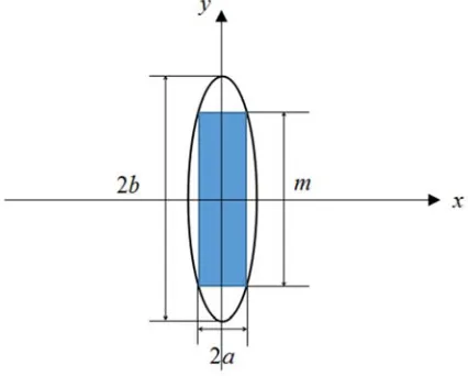
In a two-dimensional case, after a certain period of time, the contact surface of the wheel-rail is worn out, and the contact spot becomes a narrow oval. As shown in figure 1.
Figure 1. Two-dimensional Hertz contact calculation model.
Because the ellipse is long and narrow, therefore, the contact pressure of the two-dimensional wheel-rail contact can be expressed as
( )
0 1 22 1 2 xP x P
a
= −
(3)
maximum contact pressure is:
0 3 2 3 2 4 P P P m am a π π
= = (4)
4 3
m= b is the equivalent length of an elliptic contact spot.
z
P =P mrepresents the load of unit length inz-direction, equation(4)can be rewritten as
0 2Pz P
a
π
= (5)
Using the Hertz contact theory and elastic mechanics, the expression of the semi-axisais presented.
4RGPz
a
π
= (6)
where R is the wheel radius.
2 2 1 2 1 2 1 1 G E E ν ν − −
= + (7)
where E1 is the elastic modulus of the wheel, E2 is the elastic modulus of the rail,ν1is the poisson's ratio of the wheel, ν2is the poisson's ratio of the rail.
The equivalent stress at the contact spot center is written as
( )
2 2 20 2 2
3 6 3.16 1 3.16 6.32 1 6
1 1 e P φ σ φ φ φ φ φ φ = + + − + + + − + + (8) x a
φ
= (9)whereσeis the von Mise stress.
3. Finite Element Model and Material
Properties
3.1. Finite Element Model
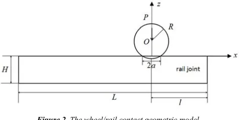
Figure 2. The wheel/rail contact geometric model.
The finite element model of wheel-rail contact is shown in figure 3. Figure 3(b)is the finite element model of resilient wheel-rail, and the rubber thickness is 60mm. The finite element grids adopt Plane183, and the contact between wheel and rail is simulated by two dimensional
surface-to-suface contact element. Method selects the extended Lagrange algorithm. The rail bottom is fully restrained while thexdirection of the center of the wheel and the x direction of the left end of the rail are restrained. Since this paper focuses on the wheel-rail contact, we do not consider contact of rubber and wheel. According to the principle of Saint Venant, the boundary constraint conditions adopted in the finite element models will not affect the stress and strain calculation results near the contact area. Since the contact area of the wheel-rail is far less than the radius of curvature of the contact surface, the stress of the contact area is far greater than that of the non-contact zone, that is, there is obvious stress concentration in the contact area. In this case, the meshing of the contact area is thicker, which can guarantee the high precision and the calculation speed. It can be seen from figure 3.
Figure 3. The finite element model.
3.2. Material Properties
Where Bi-linear Kinematic Hardening elastic-plastic material model is used for resilient wheel-rail, the material properties in Table 1.
Table 1. The properties of the materials.
Part name Modulus of elasticity(Gpa) Yield stress(Mpa) Modulus of plasticity(Gpa) Poission’s ration C10 C01
Rail 210 450 93 0.3 / /
Whell 210 450 93 0.3 / /
Rubber / / / 0.47 0.7 0.13
Figure 4. Stress-Strain curves for wheel and rail material model.
The stress-strain curves of wheel and rail are presented in figure 4, and the properties of rubber materials are determined through the Mooney-Rivilin model.
4. Results and Discussions
When P=12590N/mm, E1=E2=210Gpa, ν1=ν2=0.3, using
Hertz contact theory to calculate, we obtain a=7.64mm, P0=1049.62Mpa. In the following analysis results, the
4.1. Results of Contact Pressure
Figure 5. The distribution of contact pressure with rigid wheel-rail.
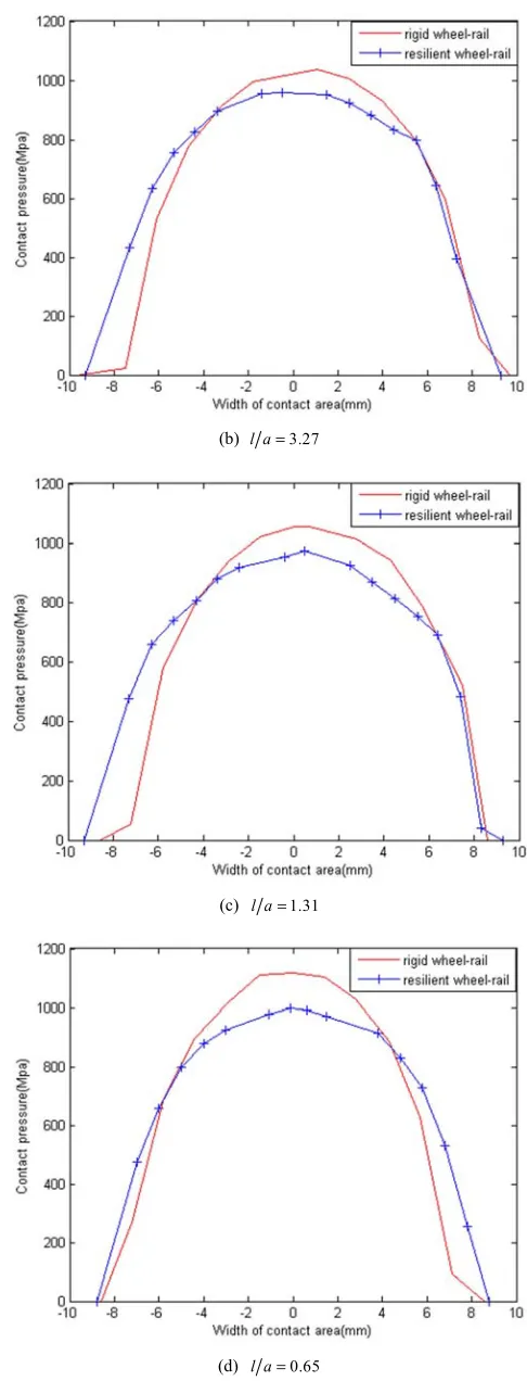
It can be seen from figure 5, when l/a=13.09, l/a=3.27 and l/a=1.31, the maximum contact pressure is 1035.47Mpa, 1035.75Mpa, 1054.73Mpa, respectively. The maximum contact pressure error is only 1.3 percent, which is consistent with Hertz contact theory, and this shows the reliability of the established finite element models. When l/a=0.65, the maximum contact pressure is 1118.18Mpa, and the error is 7 percent, which is not consistent with the Hertz contact theory. This is because the wheel-rail contact point is close to the rail joint, and the vertical contact rigidity of the rail to the free end is reduced, and the conditions does not meet the hypothesis of the Hertz contact theory, so the finite element method is used to investigate the contact analysis in rail joint. The maximum contact pressure occurred near the contact spot center, and the contact pressure increases as the distance decreasing between the contact point and the rail joint.
(a) l a=13.09
(b) l a=3.27
(c) l a=1.31
(d) l a=0.65
Figure 6. Comparison of contact pressure distribution.
rigid wheel-rail. As is seen in figure 6, the maximum contact pressure and minimum contact pressure are 999Mpa and 972Mpa, respectively, and the maximum contact pressure occurs at the contact spot center. The minimum contact pressure occurs at the periphery of the contact spot. By comparing rigid wheel-rail and resilient wheel-rail in the same conditions, it can be found that contact pressure of rigid wheel-rail is larger than resilient wheel-rail, and the contact spot width of resilient wheel-rail is basically same as rigid wheel-rail and the contact spot width above the yield limit is greater than the rigid wheel. This is due to the extrusion deformation of the rubber, absorbing part of the contact pressure and causes the wheel-rail contact pressure to be uniform.
4.2. Results of Von Mises Stress and Plastic Deformation Area
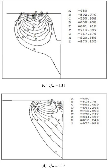
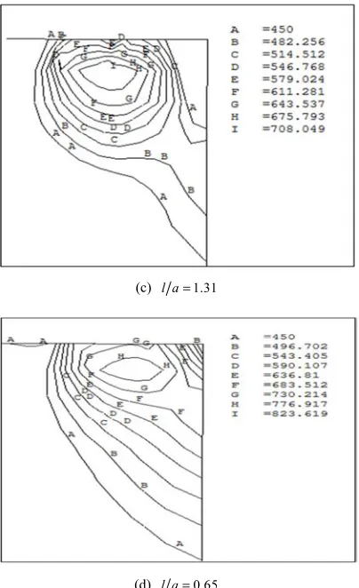
The distribution of Von Mises stress of rail for rigid and resilient wheel-rail contact model is shown in figure 7 and figure 8. It is shown that with the decrease of l, the maximum equivalent stress and the plastic deformation area of the rail increase, and the maximum equivalent stress value is closer to the rail surface, which aggravates the damage of the rail surface. As the wheel is closer to the rail joint. The equivalent stress exceeds the yield limit of the rail, and aggravates the fracture of the rail joint section. Comparing figure 7 and figure 8, the equivalent stress of the rail can be greatly reduced by using resilient wheel under the same working conditions than rigid wheel.
(a) l a=13.09
(b) l a=3.27
(c) l a=1.31
(d) l a=0.65
Figure 7. The distribution of Von Mises stress of rail for rigid wheel-rail contact model.
(a) l a=13.09
(c) l a=1.31
(d) l a=0.65
Figure 8. The distribution of Von Mises stress of rail for resilient wheel-rail contact model.
(a) l a=13.09
(b) l a=3.27
(c) l a=1.31
(d) l a=0.65
Figure 9. The distribution of Von Mises stress of rigid wheel.
The distribution of Von Mises stress of wheel for rigid and resilient wheel-rail contact model is shown in figure 9 and figure 10. Comparing figure 9 and figure 10, we obtain that using rigid wheel and using Bi-linear Kinematic Hardening elastic-plastic material model of resilient wheel, in the process of wheel-rail contact point near the rail joint, the maximum equivalent stress variation is not large. It is not difficult to find that the resilient wheel can reduce the equivalent stress and wear of the wheel.
(b) l a=3.27
(c) l a=1.31
(d) l a=0.65
Figure 10. The distribution of Von Mises stress of resilient wheel.
4.3.
σσσσ
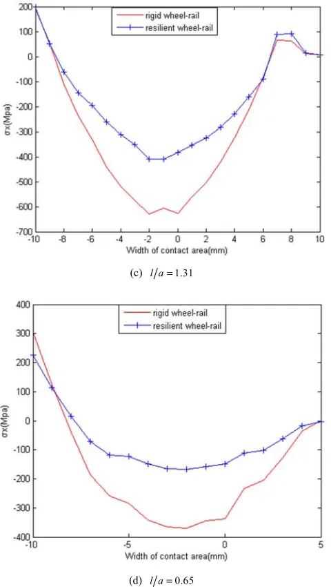
x Distribution of Rail Surface Along x AxisAs can be seen from figure 11, in the contact area of wheel - rail, σx is compressive stress, and the maximum compressive stress occurs near the center of the contact point of wheel -rail. As the distance away from the contact point, the compressive stress on both sides decreases sharply. It can be seen from figure 11 (a), (b), (c) and (d) that the compressive stress decreases with the decrease of the distance from the contact point of the wheel- rail to the rail joint. When l/a=13.09, theσxpeak value of rigid wheel along rail surface is -925.36MPa. When l/a=0.65, theσx peak value of rigid wheel along rail surface is only -345MPa, the peak value was 0.37 times the peak value of l/a=13.09. When using the resilient wheel rail contact model, compared with rigid wheel-rail contact model, the compressive stress decreases. When l/a=13.09, theσxpeak value of resilient wheel along rail surface is -750MPa. When l/a=0.65, theσxpeak value of resilient wheel along rail surface is only -168MPa. Its value is far less than the peak value of rigid wheel along the rail surface.
(a) l a=13.09
(c) l a=1.31
(d) l a=0.65
Figure 11. σx distribution of rail surface along x axis.
Outside the contact area, σxis the tensile stress. As is seen from figure 11 (a), (b), (c) and (d) that the tensile stress sharply increases with the decrease of the distance from the contact point of the wheel- rail to the rail joint. When l/a=13.09, the
x
σ peak value of rigid wheel along rail surface is 28.46MPa. When l/a=0.65, theσxpeak value of rigid wheel along rail surface is 305MPa, the peak value was 10.71 times the peak value of l/a=13.09. When using the resilient wheel rail contact model, compared with rigid wheel-rail contact model, the tensile stress decreases. When l/a=13.09, theσxpeak value of resilient wheel along rail surface is 27.97MPa. When l/a=0.65, the σxpeak value of resilient wheel along rail surface is 226MPa. Its value is far less than the peak value of rigid wheel along the rail surface.
In the contact area and outside the contact area, the distance between the contact point of the wheel-rail and the rail joint has a great impact. As the distance between the wheel-rail
contact point and the rail joint decreases gradually, the tensile stress increases sharply. Therefore, it is easy to see the collapse of the rail at the end of the rail. When the resilient wheel-rail contact model is used, the tensile stress decreases, which can reduce the damage at the rail joint.
5. Conclusions
In this study, Hertz contact theory and finite element method are used to investigate the two dimensional wheel-rail contact model, some useful results are obtained as follows:
(1)The contact pressure increases as the distance between the contact point and the rail joint decreases. Due to the existence of the rail joint, the geometrical conditions of the wheel-rail contact are not in accordance with the hypothesis of Hertz contact theory, so it cannot be solved by the Hertz contact theory.
(2)Maximum equivalent stress and the plastic deformation areas of the rail gradually increases with the distance decreasing of the contact point to the rail joint, while the equivalent stress variation of the wheel is not significant.
(3)As the distance between the wheel-rail contact point and the rail joint decreases gradually, the tensile stress increases sharply. Therefore, it is easy to see the collapse of the rail at the end of the rail. When the resilient wheel-rail contact model is used, the tensile stress decreases, which can reduce the damage at the rail joint.
Acknowledgements
The research is supported by the National Natural Science Foundation of China (No.11302159), the Young Talent Fund of University Association for Science and Technology in Shaanxi, China (No.20170519), and Basic Research Plan of Natural Science in Shannxi Province (No.2018JM5099).
References
[1] Ma C H, Shi S L, Wu Y P. Finite element analysis of the contact stress of wheel and rail [J]. Journal of shijiazhuang railway university (natural science edition), 2006, 19(3):32-35. [2] Huang L W, Zheng M L, Qi A. Mechanical property calculation
on wheel-rail linear rolling contact [J]. Chinese Journal of Construction Machinery, 2016, 14(5):403-408.
[3] K. L. Johnson, Contact Mechanics [M]. Cambridge University Press, Cambridge, UK, 1985.
[4] Kalker J J, Johnson K L. Three-Dimensional Elastic Bodies in Rolling Contact [M]. Kluwer Academic pub, 1990.
[5] Huang L, Li Z, Li L, et al. Methods to calculate accurate wheel/rail contact positions and static contact stress levels [J]. Proceedings of the Institution of Mechanical Engineers Part F Journal of Rail & Rapid Transit, 2016, 230(1):138-150. [6] Norton, RobertL. Machine design: an integrated approach /
[7] J. E. Shigley and C. R. Mischke, Mechanical Engineering Design, 6th edition [M]. Mc Graw Hill, 2001.
[8] Arslan M A, Kayabaşı O. 3-D Rail–Wheel contact analysis using FEA [J]. Advances in Engineering Software, 2012, 45(1):325-331.
[9] Aalami M R, Anari A, Shafighfard T, et al. A Robust Finite Element Analysis of the Rail-Wheel Rolling Contact [J]. Advances in Mechanical Engineering, 2013, 5(3):833-839. [10] Sharma S K, Sharma S K, Sharma S K. Dynamics analysis of
wheel-rail contact using FEA [C] International Conference on Vibration Problems. 2015.
[11] Gu S, Yang X, Zhou S, et al. An innovative contact partition model for wheel/rail normal contact [J]. Wear, 2016, s 366-367:38-48.
[12] Liu Y, Liu L, Mahadevan S. Analysis of subsurface crack propagation under rolling contact loading in railroad wheels using FEM [J]. Engineering Fracture Mechanics, 2007, 74(17):2659-2674.
[13] Farjoo M, Daniel W, Bellette P, et al. Field statistical and finite element analysis of rail squats [J]. Engineering Fracture Mechanics, 2013, 109(3):117-129.
[14] Wen Z F, Jin X S, Zhang W H. Finite element analysis of contact-impact of wheel/rail at rail gap [J]. Tribology, 2003, 23(3):240-244.