High Availability in WebSphere
Messaging Solutions
Bharat Bhushan
Sook Chua
Carolyn Elkins
Mark Scicluna
Wei-Dong Yang
Design WebSphere solutions for
high availability
Use WebSphere features to
increase availability
Use PowerHA clusters to
increase availability
High Availability in WebSphere Messaging
Solutions
April 2010
First Edition (April 2010)
This edition applies to WebSphere Message Broker V7, WebSphere MQ V7, IBM DataPower Appliance XI50 3.8.0.
Note: Before using this information and the product it supports, read the information in
Contents
Notices . . . ix
Trademarks . . . x
Preface . . . xi
The team who wrote this book . . . xi
Now you can become a published author, too! . . . xiii
Comments welcome . . . xiii
Stay connected to IBM Redbooks . . . xiv
Part 1. High availability concepts . . . 1
Chapter 1. Introduction to availability . . . 3
1.1 System availability terms and definitions . . . 4
1.1.1 Availability . . . 4 1.1.2 High availability . . . 4 1.1.3 Continuous availability . . . 4 1.2 Causes of downtime . . . 5 1.3 Availability classes . . . 5 1.4 Redundancy . . . 7 1.5 Failover strategies . . . 8 1.6 Software clustering . . . 9 1.7 Hardware redundancy . . . 11 1.7.1 Component redundancy . . . 12 1.7.2 Storage redundancy . . . 12 1.7.3 Server redundancy . . . 13
1.8 Cost of high availability . . . 13
Chapter 2. Application design for availability. . . 15
2.1 Introduction . . . 16
2.2 Message design and high availability . . . 17
2.2.1 Synchronous versus asynchronous messaging . . . 17
2.2.2 Affinity . . . 18
2.2.3 Sequencing . . . 21
2.2.4 Transactionality . . . 23
2.3 Data storage and high availability . . . 25
2.4 Cloud computing and high availability . . . 26
2.5 Keeping the network available . . . 27
2.6.2 Network patterns . . . 30
Chapter 3. Product technologies for high availability . . . 33
3.1 High availability and failover . . . 34
3.2 Hardware clustering . . . 34
3.2.1 IBM PowerHA cluster . . . 36
3.3 Multi-instance queue managers and brokers . . . 40
3.3.1 Multi-instance queue managers . . . 41
3.3.2 Multi-instance brokers . . . 41
3.3.3 Highly available hardware solutions versus multi-instance solutions . . . 41
3.4 Queue manager cluster . . . 42
3.4.1 Cluster queue managers and repositories . . . 42
3.4.2 Workload balancing. . . 43
3.5 Queue-sharing groups. . . 45
3.5.1 Benefits of shared message queues . . . 46
3.5.2 Benefits of shared channels . . . 46
3.5.3 Large messages on shared queues . . . 47
3.6 MQ clients . . . 48
3.6.1 Automatic client reconnection . . . 48
3.6.2 WebSphere MQ transactional client group unit of recovery . . . 50
3.6.3 Client connection balancing . . . 51
3.6.4 Network sprayers . . . 53
Chapter 4. Operational considerations . . . 55
4.1 Overview . . . 56
4.2 Monitoring and alerting . . . 56
4.3 Configuration management . . . 58
4.3.1 Deployment scenario 1: The big bang . . . 59
4.3.2 Deployment Scenario 2: Multiple deployment units . . . 60
4.3.3 Deciding how to break down the application into deployment units . . . 61
4.4 Capacity planning . . . 61
4.5 Hardware reliability . . . 62
4.6 Managing the application configuration . . . 62
4.7 General considerations . . . 63
4.7.1 Service support processes . . . 63
4.7.2 Testing . . . 63
5.1 Scenario overview . . . 70
5.2 High availability characteristics of the scenario . . . 71
5.3 PowerHA cluster . . . 73
5.3.1 HA cluster topology and configuration . . . 73
5.3.2 Topology and resource group . . . 76
5.3.3 Creating a cluster . . . 86
5.4 Integration of application components. . . 91
5.4.1 A solution using one resource group. . . 92
5.4.2 WebSphere MQ . . . 92
5.4.3 WebSphere MQ FTE. . . 94
5.4.4 Including WebSphere Message Broker. . . 97
5.5 Making file transfer highly available . . . 100
5.5.1 Testing the basic cluster functions . . . 100
5.5.2 File transfer tests in the cluster environment . . . 103
5.5.3 Cluster takeover tests during file transfer . . . 104
5.6 Summary . . . 105
Chapter 6. Using multi-instances queue managers and brokers for high availability . . . 107
6.1 Overview . . . 108
6.2 System environment and configuration . . . 109
6.2.1 Network plan . . . 109
6.2.2 High availability characteristics . . . 110
6.3 AIX configuration . . . 111
6.3.1 Software installed on the AIX systems . . . 112
6.3.2 Preparing the shared disk on AIX . . . 112
6.3.3 Exporting the file systems using NFS V4 mount . . . 114
6.4 Configuring the messaging components . . . 115
6.4.1 WebSphere MQ with multi-instances . . . 115
6.4.2 WebSphere Message Broker with multi-instances . . . 120
6.5 Publish/subscribe in MQ cluster test environment . . . 122
6.5.1 Setting up Queue manager cluster . . . 124
6.5.2 Creating the topic . . . 129
6.5.3 Creating the subscription . . . 134
6.6 Testing the topology . . . 136
6.6.1 Testing approach . . . 136
6.6.2 Verifying the status on the node . . . 138
6.6.3 Test cases and results . . . 139
6.7 Summary . . . 146
Chapter 7. High availability through redundancy. . . 147
7.1.2 High availability characteristics and actions . . . 151
7.1.3 Recovery . . . 155
7.2 Message Broker message flow design . . . 156
7.3 WebSphere Message Broker configuration. . . 158
7.3.1 Creating the brokers and queue managers. . . 159
7.3.2 Creating the execution groups . . . 159
7.3.3 Deploying the bar file on the server . . . 160
7.3.4 Build the second WebSphere Message Broker server . . . 162
7.3.5 Determining the URLs for the deployed Web services . . . 162
7.4 WebSphere MQ configuration . . . 163
7.5 DataPower configuration . . . 163
7.6 Operational considerations . . . 174
7.6.1 Capacity planning . . . 174
7.6.2 Message dependencies . . . 174
7.7 Testing the topology . . . 174
7.7.1 Testing approach . . . 174
7.7.2 Test cases and results . . . 175
Chapter 8. Duplexing WebSphere MQ structures . . . 183
8.1 Scenario overview . . . 185
8.1.1 Topology . . . 187
8.1.2 High availability characteristics and actions . . . 187
8.1.3 Recovery . . . 188
8.2 Coupling facility configuration . . . 188
8.3 WebSphere Message Broker configuration. . . 191
8.4 WebSphere MQ configuration . . . 192
8.4.1 Defining the coupling facility structures to WebSphere MQ . . . 192
8.4.2 Defining the shared queues . . . 194
8.5 Operational considerations . . . 195
8.5.1 Backing up WebSphere MQ structures . . . 195
8.5.2 Recovering a WebSphere MQ structure . . . 196
8.5.3 DB2 impact for large messages . . . 196
8.6 Testing the topology . . . 197
8.6.1 Testing tools . . . 197
8.6.2 Testing approach . . . 197
8.6.3 Test cases and results . . . 198
8.7 Summary . . . 211
9.2 WebSphere MQ configuration . . . 216
9.3 CICS definitions. . . 217
9.4 Testing the topology . . . 219
9.4.1 Test cases and results . . . 219
9.4.2 Test case 1: Automatic queue manager switch . . . 220
9.4.3 Test case 2: No automatic queue manager switch . . . 222
Part 3. Appendixes . . . 225
Appendix A. QPUB Transaction . . . 227
QPUBCBL program . . . 228
Trigger message . . . 228
Publish control message . . . 229
Status message . . . 229
QPUBCBL flow . . . 230
CICS definitions . . . 230
QPUB transaction definition . . . 231
QPUBCBL program definition . . . 232
Installing the definitions . . . 232
WebSphere MQ definitions . . . 233
Process definition . . . 234
Queue definitions . . . 234
Topic definitions . . . 236
Sample data . . . 236
QPUBCBL program code . . . 237
Related publications . . . 247
IBM Redbooks . . . 247
Other publications . . . 247
Online resources . . . 248
How to get Redbooks . . . 248
Notices
This information was developed for products and services offered in the U.S.A.
IBM may not offer the products, services, or features discussed in this document in other countries. Consult your local IBM representative for information on the products and services currently available in your area. Any reference to an IBM product, program, or service is not intended to state or imply that only that IBM product, program, or service may be used. Any functionally equivalent product, program, or service that does not infringe any IBM intellectual property right may be used instead. However, it is the user's responsibility to evaluate and verify the operation of any non-IBM product, program, or service.
IBM may have patents or pending patent applications covering subject matter described in this document. The furnishing of this document does not give you any license to these patents. You can send license inquiries, in writing, to:
IBM Director of Licensing, IBM Corporation, North Castle Drive, Armonk, NY 10504-1785 U.S.A.
The following paragraph does not apply to the United Kingdom or any other country where such provisions are inconsistent with local law: INTERNATIONAL BUSINESS MACHINES CORPORATION
PROVIDES THIS PUBLICATION "AS IS" WITHOUT WARRANTY OF ANY KIND, EITHER EXPRESS OR IMPLIED, INCLUDING, BUT NOT LIMITED TO, THE IMPLIED WARRANTIES OF NON-INFRINGEMENT, MERCHANTABILITY OR FITNESS FOR A PARTICULAR PURPOSE. Some states do not allow disclaimer of express or implied warranties in certain transactions, therefore, this statement may not apply to you. This information could include technical inaccuracies or typographical errors. Changes are periodically made to the information herein; these changes will be incorporated in new editions of the publication. IBM may make improvements and/or changes in the product(s) and/or the program(s) described in this publication at any time without notice.
Any references in this information to non-IBM Web sites are provided for convenience only and do not in any manner serve as an endorsement of those Web sites. The materials at those Web sites are not part of the materials for this IBM product and use of those Web sites is at your own risk.
IBM may use or distribute any of the information you supply in any way it believes appropriate without incurring any obligation to you.
Information concerning non-IBM products was obtained from the suppliers of those products, their published announcements or other publicly available sources. IBM has not tested those products and cannot confirm the accuracy of performance, compatibility or any other claims related to non-IBM products. Questions on the capabilities of non-IBM products should be addressed to the suppliers of those products.
This information contains examples of data and reports used in daily business operations. To illustrate them as completely as possible, the examples include the names of individuals, companies, brands, and products. All of these names are fictitious and any similarity to the names and addresses used by an actual business enterprise is entirely coincidental.
COPYRIGHT LICENSE:
This information contains sample application programs in source language, which illustrate programming techniques on various operating platforms. You may copy, modify, and distribute these sample programs in any form without payment to IBM, for the purposes of developing, using, marketing or distributing application programs conforming to the application programming interface for the operating platform for which the sample programs are written. These examples have not been thoroughly tested under all conditions. IBM, therefore, cannot guarantee or imply reliability, serviceability, or function of these programs.
Trademarks
IBM, the IBM logo, and ibm.com are trademarks or registered trademarks of International Business Machines Corporation in the United States, other countries, or both. These and other IBM trademarked terms are marked on their first occurrence in this information with the appropriate symbol (® or ™), indicating US registered or common law trademarks owned by IBM at the time this information was
published. Such trademarks may also be registered or common law trademarks in other countries. A current list of IBM trademarks is available on the Web at http://www.ibm.com/legal/copytrade.shtml
The following terms are trademarks of the International Business Machines Corporation in the United States, other countries, or both:
AIX® AppScan® CICS Connection® CICS® DataPower device® DataPower® DB2® developerWorks® HACMP™ IBM® OMEGAMON® Parallel Sysplex® PowerHA™ POWER® Rational® Redbooks® Redpaper™ Redbooks (logo) ® Solid® System Storage™ System z® Tivoli® TotalStorage® WebSphere® z/OS®
The following terms are trademarks of other companies:
ITIL is a registered trademark, and a registered community trademark of the Office of Government Commerce, and is registered in the U.S. Patent and Trademark Office.
Java, and all Java-based trademarks are trademarks of Sun Microsystems, Inc. in the United States, other countries, or both.
Preface
This IBM® Redbooks® publication is for anyone needing to increase WebSphere® messaging availability, especially people interested in the new capabilities of WebSphere MQ and WebSphere Message Broker. It discusses and demonstrates solutions to provide high availability for WebSphere
Messaging solutions. For the distributed platforms, this ranges from the
traditional PowerHA™ for AIX® to the new WebSphere MQ multi-instance queue managers and WebSphere Message Broker multi-instance brokers. For the appliance users, we included solutions for WebSphere DataPower®. For enterprises that need continuous availability of WebSphere MQ messages, MQ Queue Sharing Groups and the CICS® Group Attach features are demonstrated. The book includes guidance on HA options, such as when you might need PowerHA (or a similar solution for your platform), when the multi-instance features work for your applications, and when duplexing the coupling facility structures might be appropriate.
The team who wrote this book
This book was produced by a team of specialists from around the world working at the International Technical Support Organization, Raleigh Center.
Bharat Bhushan has over 13 years experience in the IT
industry, which includes design, development, and consulting of real-time, mission-critical applications. His interests include Information Security, Integration, Messaging, SOA, and Web 2.0-based technologies. Since joining IBM in July 2007, Bharat has lead complex and multifaceted programs of work for high profile clients. Before joining IBM, Bharat worked across Europe, the Middle East, and Africa in various technical and client management roles.
Sook Chua is a Senior Managing Consultant with IBM Business
Services. She has 16 years of technical and project management experiences in software development. Her
technical areas of expertise include object-oriented architectural design and leading custom application development using J2EE technologies. She holds a Master of Science in Software Engineering from the National University of Singapore.
Carolyn Elkins is an IT Specialist for Advanced Technical Skills
in the United States, with an emphasis on WebSphere MQ. WebSphere Message Broker and WebSphere MQ-FTE on System z® hardware. She has more than 25 years of experience in all phases of software design, development, testing, and operations. Lyn came to IBM as a professional hire, having experience at other software vendors and production environments. She has a degree in Computer Science from East Tennessee State University.
Mark Scicluna is an IT Specialist in the Application
Management Services Practice in Australia. He has 14 years of experience in the analysis, design, and implementation of software solutions, primarily in the integration of distributed systems. He has a broad range of expertise including
middleware technologies, Java/J2EE, XML, and Web Services but is primarily focussed on WebSphere MQ and WebSphere Message Broker. He holds a degree in Mathematical and Computer Science at the University of Adelaide.
Wei-Dong Yang is an IT Integration Architect in Germany. He
has worked in the IT industry for more than10 years.Since 2005, he has focused on WebSphere MQ and WebSphere Message Broker. His areas of expertise include solutions design and integration with WebSphere messaging products, HACMP™ in an AIX environment, and system implementation using
WebSphere Transformation Extender. He holds a Ph.D. in Solid® State Physics from the University of Augsburg, Germany.
Thanks to the project leader for this project: Carla Sadtler
International Technical Support Organization, Raleigh Center Thanks to the following people for their contributions to this project: Margaret Ticknor
Rich Conway
International Technical Support Organization, Raleigh Center Volker Daeschler
Hans Eisenmann IBM Germany
Mark E Taylor Andrew Schofield Jonathan Rumsey Brian Stewart IBM UK
Now you can become a published author, too!
Here's an opportunity to spotlight your skills, grow your career, and become a published author - all at the same time! Join an ITSO residency project and help write a book in your area of expertise, while honing your experience using leading-edge technologies. Your efforts will help to increase product acceptance and customer satisfaction, as you expand your network of technical contacts and relationships. Residencies run from two to six weeks in length, and you can participate either in person or as a remote resident working from your home base.
Find out more about the residency program, browse the residency index, and apply online at:
ibm.com/redbooks/residencies.html
Comments welcome
Your comments are important to us!
We want our books to be as helpful as possible. Send us your comments about this book or other IBM Redbooks publications in one of the following ways:
Use the online Contact us review Redbooks form found at:
ibm.com/redbooks
Send your comments in an e-mail to:
[email protected] Mail your comments to:
IBM Corporation, International Technical Support Organization Dept. HYTD Mail Station P099
2455 South Road
Stay connected to IBM Redbooks
Find us on Facebook:
http://www.facebook.com/pages/IBM-Redbooks/178023492563?ref=ts Follow us on twitter:
http://twitter.com/ibmredbooks Look for us on LinkedIn:
http://www.linkedin.com/groups?home=&gid=2130806
Explore new Redbooks publications, residencies, and workshops with the IBM Redbooks weekly newsletter:
https://www.redbooks.ibm.com/Redbooks.nsf/subscribe?OpenForm Stay current on recent Redbooks publications with RSS Feeds:
Part 1
High availability
concepts
This part provides information about high availability concepts and includes an overview of techniques and products that can be used to achieve high availability.
Chapter 1.
Introduction to availability
At one time or another, most of us have experienced an ATM service not being available to dispense cash or an online service being unavailable for access due to maintenance. Or a time when a customer service representative asks you to call back later because their system is down. Or you click a button and receive a
500 Internal Server Error response.
These scenarios are typical system outages. The ATM and online service examples are typically planned outages intended for maintenance work. These outages are usually scheduled at quiet times with low activity for a predetermined amount of time. The customer service representative (CSR) and transaction error examples, however, are unplanned outages due to hardware or software failures. Occurrences during peak time have significant impacts and serious consequences where critical systems are involved.
As IT becomes more pervasive in businesses and our daily lives, the impact of downtime is increasingly significant. Outages affect productivity, create
inconveniences, and result in loss of business. Increased dependence on IT increases needs for highly available systems. Globalization of business places a new demand for systems to be highly available and continuously operational. This 24X7 availability calls for the elimination of unplanned and planned outages. This chapter begins with definitions of system availability terms followed by causes of unplanned outages. It includes a discussion on high availability measurement, failover strategies, and software and hardware redundancies. The chapter concludes with a discussion on factors to consider in the design of a high
1.1 System availability terms and definitions
In this section, we define high availability and continuous availability as well as discussing the differences between these two availability concepts.
This IBM Redbooks publication focuses on high availability for IBM WebSphere Messaging products.
1.1.1 Availability
Availability in this context is a measure of the accessibility of a system or application, not including scheduled downtime. It can be measured as a ratio of expected system up-time relative to the total system time, which includes uptime and recovery time when the system is down. The following formula illustrates this concept:
A = [MTBF/(MTBF + MTTR)] x 100%
The following definitions apply to terms in the this equation:
MTBF: Mean Time Between Failure. This is the average elapsed time between failures
MTTR: Mean Time To Recover, This is the average time required to recover from a failure
1.1.2 High availability
High availability refers to the ability of a system or component to be operational and accessible when required for use for a specified period of time. The system or component is equipped to handle faults in an unplanned outage gracefully to continue providing the intended functionality.
1.1.3 Continuous availability
Continuous availability refers to the ability of a system or component to be operational and accessible when required for use at all times. The system or component is designed such that a user experiences zero downtime.
1.2 Causes of downtime
System downtime results from planned or unplanned events. Planned downtime can often account for a significant amount of the total downtime. The optimal situation is for systems to be in continuous operation without scheduled down time for maintenance work. However, a long running system is more prone to failures that result in unplanned outages. Such unplanned outages are costly, with significant impacts. Naturally, a user wants to reduce or eliminate these outages.
Studies show that software failures and human errors are the major causes of unplanned outages. Other causes include hardware or infrastructure failures, site disasters, and natural calamities.
The key to implementing a high availability system is to identify and eliminate single points of failure through redundancies, clustering, and failover
mechanisms.
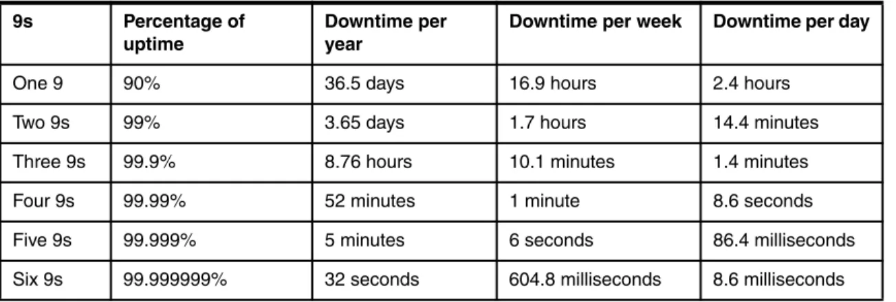
1.3 Availability classes
Availability is usually in “9s” notation. Table 1-1 shows six classes of “9s” and their corresponding downtime hours.
Table 1-1 Six classes using 9s notation
9s Percentage of
uptime
Downtime per year
Downtime per week Downtime per day
One 9 90% 36.5 days 16.9 hours 2.4 hours
Two 9s 99% 3.65 days 1.7 hours 14.4 minutes
Three 9s 99.9% 8.76 hours 10.1 minutes 1.4 minutes
Four 9s 99.99% 52 minutes 1 minute 8.6 seconds
Five 9s 99.999% 5 minutes 6 seconds 86.4 milliseconds
A 99% highly available system has a 1% of downtime in its useful life. A more accurate translation of downtime depends upon the system’s scheduled operational hours. For example:
System A is scheduled for 24 hours per day, 365 days per year. A 1% downtime equals 87.6 hours.
System B is scheduled for 8 hours per day, 5 days per week. A 1% downtime equals 20.8 hours.
These hours, however, do not indicate system’s maximum downtime at one time and frequency of downtime.
Continuing with these examples, we can calculate the potential downtime in terms of days:
System A’s 87.6 hours of downtime is equal to 3.65 days of unavailability at one time.
System B’s 20.8 hours of downtime is equal to 0.87 days of unavailability at one time.
Depending upon the business nature, these maximum downtime durations might not be acceptable.
Another important parameter is the frequency of downtime. Consider System C, which is allowed 2.4 hours downtime per day. If the system is down on average for one minute, this means it can go down 144 times a day. Reliability of this system can be considered questionable. As you can see, high availability does not imply reliability.
Understanding these distinctions is important when designing a system that satisfies agreements reached between clients and providers with regard to availability. As companies move towards a service-oriented architecture (SOA), the availability aspect of these service level agreements becomes critical. The ideal service is available to business processes at all times.
1.4 Redundancy
Consider a system made up of three serial components with two linkages, as shown in Figure 1-1.
Figure 1-1 System redundancy example
In Figure 1-1, the system = A1 + B1 + C1 + L1 + L2.
All components and links have 99.999% availability, except for B1 which has 90% availability. The system’s availability is calculated as shown in the following equation:
System Availability = (0.99999) * (0.99999) * (0.90) * (0.99999) * (0.99999) = 89.96%
The system availability drops drastically below 90%. All the “five 9s” components do not compensate for the single “one 9” component. The old saying that a chain is only as strong as its weakest link is certainly true of a system with serial components. Besides, each serial component is a single point of failure. Suppose the system configures a pair of B components in parallel fashion for redundancy, as in Figure 1-2.
Figure 1-2 System redundancy example
A1 L1 B1 L2 C1
A1 L1 C1
B1
L2
The availability of this parallel configuration is as shown in the following equation:
Availability of B1/B2 = 1 – [(1-0.90) * (1-0.90)] = 0.99
With the parallel configuration, the system availability is recalculated as shown in the following equation:
System Availability = (0.99999) * (0.99999) * (0.99) * (0.99999) * (0.99999) = 98.99%
Redundancy eliminates single points of failure and increases availability. It is a key design consideration in a highly available system. 1.5, “Failover strategies” on page 8 explores the failover strategies available in redundancy.
1.5 Failover strategies
Redundancies mask system and component failures from users. The
transparency of failure masking depends upon the following failover strategies:
Cold standby
In this failover strategy, the primary component runs actively while the secondary or backup component stays dormant. When the primary
component fails, the secondary component is activated to assume an active role. The interruption is visible to users.
Warm standby
In this failover strategy, the primary component runs actively with the secondary or backup component running without active participation in workload management. The secondary component receives frequent data updates from the primary component, which means that there are times when both components are not synchronized. When the primary component fails, the secondary component assumes an active role. Because the secondary component has been running passively with partial data, the fail over is faster than a cold standby, with minimal interruption to users.
Hot standby
In this failover strategy, the primary and secondary components are actively running as a single, unified system. Active data replication happens between the primary and secondary components. When the primary component fails, the secondary component continues functioning without interruption to users.
1.6 Software clustering
Clustering is a technique to create multiple copies of components running actively and collaborating seamlessly to present a single, unified system. There are three modes of clustering:
Vertical clustering
In vertical clustering (Figure 1-3), multiple copies of the components are running actively on the same physical machine. The components are hot standby or in active replication. This means that failure of one component presents no visible interruption to users. This clustering technique optimizes use of the machine. However, the single physical machine presents a single point of failure.
Figure 1-3 Vertical clustering
Vertical Clustering
Machine A Process
Horizontal clustering
In horizontal clustering (Figure 1-4), components are created on multiple physical machines. This clustering mode achieves similar software redundancy in vertical clustering with the additional benefit of hardware redundancy.
Figure 1-4 Horizontal clustering
Vertical and horizontal clustering
Combining vertical and horizontal clustering techniques maximizes use of individual physical machines to achieve high availability, performance throughput and scalability. See Figure 1-5.
Horizontal Clustering Machine A Machine B Process Process Horizontal Clustering Vertical Clustering Machine A Machine B Process Process Process Process
IBM WebSphere products have inherent support for clustering. The clustering techniques supported by the WebSphere products in this book are as shown in Table 1-2.
Table 1-2 Clustering techniques supported by IBM WebSphere products
Besides inherent clustering capability, IBM WebSphere products can also be used with external clustering software such as IBM PowerHA for AIX and IBM Tivoli® System Automation to achieve redundancy.
For more detailed information about PowerHA for AIX setup, see the PowerHA for AIX documentation available in the PowerHA for AIX library at the following Web page:
http://www.ibm.com/servers/eserver/pseries/library/hacmp_docs.html
For more information about Tivoli System Automation Resource Managers, see the IBM Tivoli System Automation for Multiplatforms Guide and Reference at the following Web page:
http://publib.boulder.ibm.com/tividd/td/ITSAFL/SC33-8210-03/en_US/PDF/h algre11.pdf
1.7 Hardware redundancy
Fault tolerance refers to the ability of a system to continue operation in case of failure of one or more of its components. This term is usually referenced with high availability, particularly at the hardware level. Hardware redundancy (the addition of extra hardware for fault detection and toleration) is commonly employed in fault tolerant systems. In this section, we address hardware redundancies at the component, storage, and server levels.
Clustering techniques
Product Vertical Horizontal Vertical + Horizontal
WebSphere Message Broker x x x
WebSphere MQ x x x
WebSphere Application Server x x x
1.7.1 Component redundancy
Component-level devices include, but are not limited to, processors, power supplies, network equipment, and so forth. The processor is the heart of an IT system and a failure constitutes a “machine stops” situation. Resilience can be achieved through multiple processors (SMP) and advanced coupled systems such as IBM Parallel Sysplex®.
An uninterruptible power supply (UPS) protects a system against power fluctuations and main power failure. It continues to supply power from a few minutes to several hours during a power outage. This increases system availability with minimal disruption to users.
Redundancies for network equipment is made through duplication. A backbone network can also be used to increase protection against hardware failures. The backbone network eliminates single point of failure by providing multiple, alternative traffic paths for communication. A redundant backbone further enhances high availability.
1.7.2 Storage redundancy
A system is rendered unusable without data, though it might be highly available or continuously operational. A comprehensive design for storage redundancy should be considered with the system’s data flows, data components, and data availability.
At a high level, storage redundancy can be achieved through the following approaches:
Disk mirroring and duplexing
Storage Area Network (SAN)
Redundant Arrays of Inexpensive Disks (RAID)
Duplicate data centers to avoid natural disasters.
IBM products such as IBM TotalStorage®, IBM System Storage™ provide solution offerings to develop resilient and secure infrastructures for data storage.
1.7.3 Server redundancy
Server redundancy through hardware clustering mitigates hardware and operating system-level failures. There are generally two modes of hardware clustering:
Active/active (also known as high availability clusters or HA clusters)
A HA cluster consists of redundant computer nodes that are used to provide service when the primary system component fails. HA clustering uses heartbeats to monitor the health and status of each computer node in the cluster. When a failure occurs, the application is restarted on the backup node automatically, a process known
failover
. The failover procedure generally involves reassignment of the failed server IP-Address to the backup server, setting file system access, and synchronization of state with the failed server before restarting the application on the backup server.There are extensive commercial implementations of HA cluster technologies, (such as IBM PowerHA for AIX) and those that are inherent with IBM Parallel Sysplex.
Active/passive (also known as load balancing clusters)
In a load balancing cluster, multiple, homogeneous computer nodes are linked to share computational workload. The cluster provides a logical view of a single virtual machine. It behaves like an HA cluster except that all computer nodes in the cluster are actively participating in the system’s workload. When a component fails, there is no failover process. Instead, the request is routed to a node in the cluster.
1.8 Cost of high availability
Enterprises increasingly demand systems and applications be highly available. Globalization of businesses has evolved this need into continuous availability. When enterprises invest in achieving high availability, the focus is on increasing redundancy in the infrastructure. However, component redundancy is only one variable in the equation. As mentioned in 1.2, “Causes of downtime” on page 5, software failures and human errors are the major causes of unplanned downtime. These can be mitigated through a series of IT management processes, such as the following examples:
Change management
This process improves system quality through better planning, testing, evaluating change impact, coordinating and scheduling of application, and IT infrastructure changes.
Problem management
This process facilitates problem logging, expedites problem identification, isolation, escalation, root cause determination with resolution, and prevention of future occurrence.
Configuration management
This process is a comprehensive understanding of relationships among IT infrastructure, applications, and business processes. Configuration management allows for a better understanding of a change's impact and facilitates problem identification and resolution.
Performance management
This process tracks end-to-end system’s health and performance. This knowledge provides faster turnaround time in problem diagnosis and resolution, thus reducing downtime.
Capacity planning
This process anticipates future IT resource needs to avoid shortages and satisfy its service-level objectives.
Availability Management
This process collects and correlates information from networks, systems, and applications to be proactive in identifying potential problems and fix them to avoid failures and downtime.
Help Desk Support system
This process provides a mechanism for users to seek assistance with system usage issues, problem reporting, problem tracking, and issue resolution.
Training
This process equips IT operational team with the skills and knowledge required to support systems. Operational team members can back up each other. Otherwise, reliance on a single resource constitutes a single point of failure.
Operational considerations are described in greater detail in Chapter 4, “Operational considerations” on page 55.
The costs for highly available systems include component redundancies and IT management processes. The cost increases with higher “9s”. It is important to understand the business needs and the impact of downtime to the business to
Chapter 2.
Application design for
availability
This chapter discusses aspects of application and infrastructure design that can affect high availability. The reader can then make an informed judgment on choosing a certain design, configuration, or deployment model to ensure the systems deliver their availability requirements.
2.1 Introduction
In Chapter 1, “Introduction to availability” on page 3, we introduced availability concepts, defined availability, and looked at the distinction between High Availability and Continuous Availability. In this chapter we expand on these concepts and consider design considerations for availability.
When designing a solution we need to consider the availability requirements of the system. This typically is derived by the business stakeholders after assessing the value of the service to the business, the impact on the business of an outage, legal or statutory requirements, and the impact on customers of an outage or poor quality of service.
Performance, quality, and availability criteria are documented as non-functional requirements (NFRs). NFRs include those attributes of an application other than its core function. The following list details attributes that might affect the
availability of an application: Security Performance Maintainability Scalability Compliance
Well-documented non-functional requirements are essential to the availability of the application, because they are key drivers for architecture and design decisions.
If performance or scalability requirements are not clearly understood and well-defined, there is a risk that the solution might not be able to handle the volume of requests. This might result in poor quality of service, slow response, or (in the worst case) an application outage.
In the rest of this chapter we expand on the concepts discussed in Chapter 1, including redundancy, workload balancing, failover, and message design and how these concepts impact high availability.
2.2 Message design and high availability
This section discusses considerations for message design with a focus on high availability. In particular, we discuss the impact of high availability designs on the following concepts:
Synchronous versus asynchronous messaging. See page 17.
Affinity. See page 18.
Sequencing. See page 21.
Transactionality. See page 23.
2.2.1 Synchronous versus asynchronous messaging
A synchronous request-reply pattern involves services that respond over the same network socket on which the request was received. The receiving application keeps the network socket open while it processes the request and when the request is ready, the receiving application responds using the same network socket.
The calling application might time out if no response is received. In this situation the network socket is closed at each end and might be reused by other
processes. Applications must resend the original request as required.
The advantage of synchronous processing is its simplicity, as there is no need to have special programming to handle asynchronous responses. This is shown in Figure 2-1. Requests that receive a response within the timeout period are processed. Any responses received after the timeout must be re-sent.
Figure 2-1 Synchronous messaging
Asynchronous messaging, on the other hand is a mechanism in which a user might submit a request but does not require an immediate response. The recipient system usually acknowledges receipt of the request message with a
Service User
Synchronous Request – Response pattern
Ti
m
e
Timeout Application
The advantage of asynchronous messaging is that it is more resilient to outages in certain parts of the architecture, as it decouples the sender from the receiver. For example, consider a service provided by an enterprise service bus (ESB) that must interface with several back-end systems. The consumer of the service can invoke the service by passing the request to the ESB. The ESB is then responsible for ensuring that the back-end system processing is performed. If there are outages in the back-end systems or network issues preventing communication, the ESB can queue the work to be performed when the interfacing systems are reachable. After processing is completed, the ESB can send an asynchronous reply to the consumer system if required.
The asynchronous request-response design pattern is shown in Figure 2-2.
Figure 2-2 Asynchronous request: Response pattern
2.2.2 Affinity
Affinity, often referred as stickiness, is the requirement to favor a particular cluster member after the first request. In a high availability solution with parallel redundant processing streams, affinity might be required to support maintenance of state information, transaction support, or in support of message sequencing. We discuss four types of affinities that might be relevant to your high availability solution:
Message affinity. See page 19.
Server affinity. See page 19.
Session affinity. See page 19.
Transaction affinity. See page 20.
Service User Message Acknowledgement Response Acknowledgement
Message affinity
When working with WebSphere MQ clusters with multiple definitions for the same queue manager, it is important to be aware of whether the application has any relationships between the messages that require message affinity. In clustered environments a message can be routed to any queue manager that has an instance of the queue.
Where possible, the application should be altered to remove the reliance on message affinities. This can be done, for example, by passing state information within the message body or by storing state information in persistent storage (such as a relational database). This improves the messaging applications scalability and availability. A group of related messages can lock resources at the destination queue manager until all of the messages have arrived and this has the effect of blocking the applications.
If it is not possible to remove message affinities, there are a number of techniques available in WebSphere MQ that support message affinity:
Specify the remote queue name and the queue manager on the MQOPEN call.
Use the reply-to queue manager field to specify the queue manager.
Specify the MQOO_BIND_ON_OPEN option in the MQOPEN call.
For more information about these options see the WebSphere MQ Information Center at the following Web page:
http://publib.boulder.ibm.com/infocenter/wmqv7/v7r0/index.jsp
Server affinity
Server affinity allows a load balancer to remember the server selected for a specific client at the initial request. Subsequent requests are routed to the same server. Although this might sound like it defeats the purpose of a load balancer, server affinity is essential to preserve state across distinct connections from a client (such as a stateful Web application).
To prevent single points of failure, redundancies of hardware load balancers and downstream servers are required. Server affinity configuration in a load balancer must be considered with session affinity for failover.
Session affinity
Session affinity is the preference of one server over others, by the load balancing mechanism in recognition of an existing session. Subsequent requests from the same client always get routed to the same server. This is typical of a Web server plug-in that always attempts to route a request that contains session information
application server is down, the plug-in attempts to route the request to an alternate application server in the cluster. The new application server makes use of memory-to-memory replication to retrieve the session information to process the request.
Session affinity is depicted in Figure 2-3. In this example, requests 1 and 2 from John are routed to Service Instance A. All requests from Bob are routed to Service Instance C.
Figure 2-3 Session affinity example
Transaction affinity
Transaction affinity is the preference of one server over others, by the load balancing mechanism in recognition of an existing transaction. An example of use is the entity bean. After an entity bean is instantiated in the EJB container, the workload management service directs all requests from the client towards that entity bean for the duration of the transaction.
For additional information about server affinity, session affinity, and transaction affinity for failover, see IBM Redbooks publication WebSphere Application Server
Network Deployment V6: High Availability Solutions, SG24-6688.
Component Service Instance A Service Instance B Service Instance C Service Instance D 1 2 1 2 John Bob 2 1 2 1
2.2.3 Sequencing
Asynchronous messaging decouples the sender from the recipient. A sender deposits a message and moves on rather than waiting for a response from the recipient. Messages that are assumed to be independent units can be consumed by any application tuned to listen for them. This allows for faster response time, higher throughput, and better scalability.
Certain business applications, however, require messages to arrive in exactly the same order as they were created and sent from the source system. For example, a banking system requires credits and debits from a bank account to arrive in the correct order to avoid the account becoming overdrawn in error.
In the case of a high availability architecture that has multiple parallel streams to process a request, it can be challenging to keep messages in sequence. Every component in the journey can affect the order in which messages arrive at their final destination, or if they arrive at all.
There are various ways to ensure that messages arrive in order. Sequencing can be provided through the messaging infrastructure or by the sending and
receiving applications.
Sequencing support within WebSphere MQ
Messages from a single application end up in the queue in the order in which they were put. However, messages can arrive out of sequence if they take seperate routes through the network, or if they are placed temporarily on a dead-letter queue. If sequencing is essential, WebSphere MQ provides support through message grouping. The sender application can specify that it is sending messages as part of a group. Within the group, messages are given a sequence number starting at 1. Message grouping can be used to ensure that a whole group of messages is available before processing starts. The receiving
application can then read the messages from the queue in the sequence order.
Sequencing support within WebSphere Message Broker
Sequencing support has been built into WebSphere Message Broker 7.0 with the introduction of the Sequence node and the Resequence node. The Sequence node provides the ability to add sequence numbers to messages belonging to a group to preserve the order in which the messages arrive. The node property
Path to sequence group identifier tells the node where to read the group identifier. All messages arriving with this group identifier are allocated a
sequence number, which is stored in the Path to store sequence number node property, for example, the LocalEnvironment, MQRFH2 header or the message body.
The Resequence node can be used to control the order in which messages are processed. Messages within a sequence group can arrive in any order and are stored by the Resequence node. Messages are then propagated in sequence. If there is a gap in the sequence, the Resequence node waits for the missing messages for a specified period.
To take advantage of this new functionality in a high availability scenario with multiple flow instances spread across multiple brokers, you need to ensure message flow affinity.
Application provided sequencing
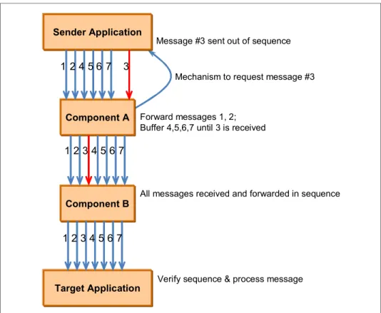
The sender and receiver applications can be responsible for message sequencing based on an agreed approach. This might include the sender application placing sequencing information in the message body. The receiving application is then responsible for processing the messages in the correct sequence. Any messages that arrive out of sequence must be buffered until the next message in the sequence is received. In more sophisticated variations on this approach, the sender and receiver might have a set of agreed protocols for handling missing messages including the use of acknowledgements, negative acknowledgements, and requests for a message to be resent.
Error handling and retry mechanisms might result in messages being resent. This can mean that requests are processed more than once. To avoid this, a form of message identification (such as a unique ID) should be built into the message structure. Messages that are resent due to errors retain the same unique identifier. It is the responsibility of the receiving system to monitor the identifiers of messages processed to ensure that messages are not processed twice. The flow of messages in such a design is shown in Figure 2-4 on page 23. In this figure, an intermediate component, Component A, is used to handle message sequencing.
Figure 2-4 Application design to handle message sequencing
2.2.4 Transactionality
Applications and systems transact with other applications and systems using messages containing data that might be proprietary or standards-based. The transaction might cover all parties involved or a sub-set. All applications involved in a transaction must ensure data consistency and integrity. In a transactional system, either all operations must succeed or there must be a way to rollback or undo partial transactions. When the transaction is completed, a commit might be issued that makes all data changes (insert, update, or delete) permanent. A business transaction might be different from a technical messaging transaction. A single business transaction involves at least one message exchange between two parties or systems.
Sender Application
Component A
Target Application Component B
Forward messages 1, 2; Buffer 4,5,6,7 until 3 is received
Message #3 sent out of sequence
Mechanism to request message #3
All messages received and forwarded in sequence
Verify sequence & process message
1 24 5 6 7 3
1 23 4 5 67
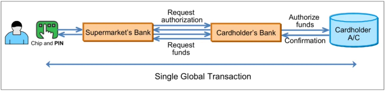
Figure 2-5 represents a simplified transactional model of a debit/credit card authorization.
Figure 2-5 Single global transaction
When a customer makes a purchase using a debit card and enters a personal identification number (pin) in the entry device, the transaction is handled by the supermarket’s bank which, using a service provider, connects to customer’s bank to request authorization of funds. Several small messages are exchanged between all parties and, depending on funds available, the customer’s bank makes the decision whether to accept the authorization or decline the payment. The message delivery mechanism can affect the transactionality. The following options are available for consideration and can be elected based on the criticality:
One-time delivery with no duplicates.
In Figure 2-5, an authorization request from the till must be sent only once and in a transactional fashion. A customeris not happy if he is charged twice for the same transaction.
Guaranteed delivery with the possibility of duplicates.
An example is a weather update application that issues storm warnings. The warnings must be delivered, but there is no harm if duplicate copies are received. In fact, in this particular example, duplicate messages might even be a good thing.
No delivery guarantee; the best effort only.
A Web-based instant messaging system can be designed using this option. If an instant message was lost or undelivered, the user can resend the
message instantly.
Application design for a highly available system can be complicated when
Single Global Transaction
Authorize funds Confirmation Request authorization Request funds
Chip and PIN
Supermarket’s Bank Cardholder
A/C Cardholder’s Bank
Transactions and HA can coexist in a solution. One exception is where two-phase (XA) commit and failover meet. You need to ensure that the transaction manager can contact the queue manager following a failover. It is vital to get the queue manager running again in these situations. Simple redundancy is not enough.
2.3 Data storage and high availability
Data is an integral part of every system, because without data a system’s usefulness diminishes. Many messaging applications make use of data in databases. Consider the availability of the databases as part of your overall high availability solution. In most situations this consists of a highly available database connected to the messaging applications across a network. This is not the only consideration, however. Data can be in-flight, stored on a file system, or stored in a database. In a high-volume, high-concurrency environment, maintaining data consistency and integrity is challenging.
The following list defines three classes of data. We look at ways in which these classes of data can be made highly available. Application data can be broadly classified as follows:
Static data
Data resides on a disk and is loaded into memory for caching purposes during the system’s operation. Modifications are planned and scheduled. Examples of static data include HTML pages, XSD schema files, and configuration files.
Transient data
Data is briefly at rest on a disk when the system is running. An example of transient data is a message briefly at rest in a WebSphere MQ queue before the next hop.
Volatile data
Data with frequent accesses and updates while system is running. This data might reside in memory (for example session data, entity bean data, and in-memory JNDI caches) or reside in a back-end database.
Resilience for static data stored on disk can be provided by the use of shared disks or RAID technology.
High availability can be provided for volatile in-memory data through
memory-to-memory replication to eliminate single point of failure. For further information about memory-to-memory replication see IBM Redbooks publication
WebSphere Application Server Network Deployment V6: High Availability Solutions, SG24-6688.
A highly available back-end database is crucial and can be made available through database clustering. Modern database solutions might employ parallel processing or hot standby with active data replication on a horizontal hardware cluster with heartbeat monitoring. The highly available database solution must also preserve transaction integrity during failover.
For details on IBM disk technologies with DB2® database for high availability, see IBM Redbooks publication High Availability and Disaster Recovery Options
for DB2 on Linux, UNIX, and Windows, SG24-7363.
2.4 Cloud computing and high availability
Many corporations have a strategy to move towards a cloud computing delivery model. Cloud computing provides a delivery and consumption model for IT services where the IT infrastructure is a managed service somewhere on the Internet (hence the cloud). Resources (including hardware, software, and business and Internet applications) can be dynamically allocated or de-allocated in minutes through virtualized environments based on use and demand. This eliminates the need for an organization to buy, maintain, and refresh expensive IT infrastructures (such as networks and servers).
There are pros and cons for cloud computing that are not debated here. From a high availability perspective, however, you must ensure that you are dealing with a reputable service provider that provides the following skill sets:
Demonstrates that they have the maturity and organizational mechanisms in place to support the infrastructure properly. This includes back-up and recovery, disaster recovery, and support processes.
Agrees to your organizations service level requirements.
Meets your organizations service level requirements.
For further information about IBM’s cloud offering see the following Web page:
2.5 Keeping the network available
All organizations have layers of networks protecting their key applications, systems, and data. These layers are often labeled as red, yellow. and green zones. These zones depict perimeters of networks, subnetworks, and associated levels of trust on the systems, connections, data, and users in a zone. Zones closer to the edge have lower levels of trust, so all connections and data are scrutinized. As you get closer to the green zone, there is higher level of trust. In the early 70’s networks were designed as castles; a huge wall (firewall) on the outside and freedom to move anywhere inside. The challenge with this design was that anyone who got past the big wall can do anything they want. They can weaken the wall from inside, steal information, or stay inside the wall and weaken systems and steal information for as long as possible.
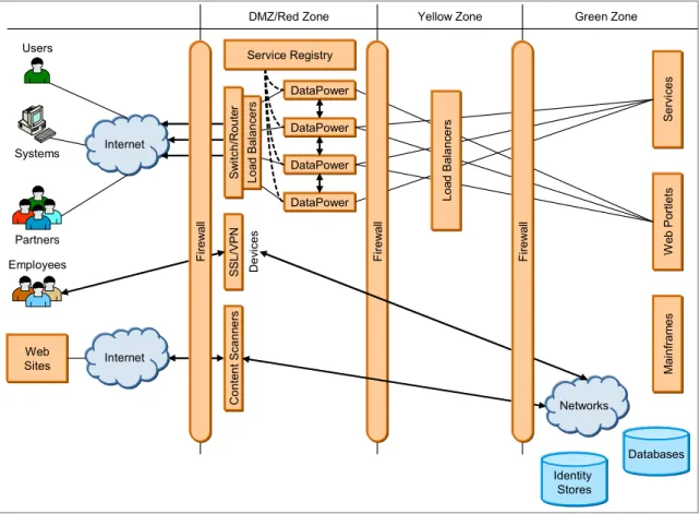
Modern networks, however, are designed like airports. There are checks and barriers at various stages of before you are allowed to board the airplane. This concept is illustrated in Figure 2-6 on page 28.
The DMZ (demilitarized zone) is often a part of the network that exposes an organization services to the outside world in such a manner that no one can bypass security policies and can only access exposed services. There are specialty devices (such as firewalls, switches, load balancers, XML firewalls, and anti-virus scanners) that inspect connections and content passing through the connection. Some devices are content-aware and some are stateless devices that check, detect, and stop any potential threats to the protected resources.
Figure 2-6 Network layers in a topology
Figure 2-6 shows a simplified version of a network topology. The DMZ contains specialist devices (such as DataPower) responsible for the following tasks:
Service virtualization
SSL connection initiation/termination
Cryptographic functions such as encryption, decryption, signature, verification
Message schema based checks
Security policy enforcement
Authentication, Authorization etc.,
XML threat protection
Other specialized content filters might be scanning for viruses and Trojans within
Conte n t S cann er s
DMZ/Red Zone Yellow Zone Green Zone
Identity Stores Networks M a in fr am es We b P or tle ts Se rv ic e s DataPower DataPower DataPower DataPower Service Registry SSL /VPN De vi ce s Internet Loa d B al anc er s S w itch/R oute r Web Sites Internet Users Partners Employees Systems Fi re w al l Fi re w al l Loa d B al a nc e rs Firew al l Databases
2.6 Infrastructure patterns
Most IT operations teams use design patterns for hardware and software deployment. These patterns are based on industry-accepted practices, individual experiences, project requirements and policy compliance. Sometimes the technologies used might also influence and dictate the pattern in which it is deployed and managed. Every new deployment must go through an exercise of vetting the applicable patterns and making a choice based on cost, risk, and the value of the service being hosted.
In this sections that follow, we examine infrastructure-related design patterns. In particular we look at the following topics:
“Cluster patterns”
“Network patterns” on page 30
2.6.1 Cluster patterns
Section 1.6, “Software clustering” on page 9 discusses software clustering. Software clustering is an important element in the design for redundancy, fault tolerance, resilience, and high availability. A cluster eliminates single points of failure. An important aspect, however, is whether to share state, context, and data between cluster nodes so that failure of a cluster node is invisible to the client applications and that from their point of view, everything continues as normal.
The following four patterns are found in cluster-based deployment:
Cluster members have their own data stores and file systems where they operate and the data is not shared with other cluster members.
In this scenario there is a possibility that data might not be recoverable from a failed node. For example, DataPower devices are typically deployed where each device has its own file system. In case of a device failure, all in-flight transactions are lost and any files or data kept on the local file system is also lost.
Cluster members share common storage (database or file systems) but work as independent nodes.
In this case, both nodes can be configured as active and they continue to use their own resources and use their own data sets. For example, two nodes might share a database but might have their own tables, views, and so forth.
Cluster members share common storage and data sets, so two or more nodes might update the same file, database table, or record at the same time. Appropriate logic needs to be in place to maintain data integrity and avoid file or record locking.
Cluster members are deployed in geographically dispersed locations to avoid natural or man-made disasters.
The distance between cluster nodes might be from a few miles to thousands of miles. Hardware- or software-level data replication technologies are employed to replicate data across sites.
2.6.2 Network patterns
Section 1.4, “Redundancy” on page 7 discusses redundancy and how adding redundant components in the network increases high availability. As shown in Figure 2-7, daisy-chained components represent a single point of failure as they do not allow for an alternative route in the event of a component failure. A failure of any individual component might result in an outage of the entire application infrastructure.
Figure 2-7 Daisy chains: Bad for high availability
To overcome this obstacle, we can employ redundant components (shown in Figure 2-8). Network connectivity between the redundant components ensures that all components in the architecture are reachable even if one or more components fail. Redundant components can be added in an active pattern where they are actively participating in processing transactions. For push-based technologies (such as HTTP), a load balancer can distribute the traffic equally on the available components.
Figure 2-8 Active–active configuration
Component B Component C Component A Component C Component B Component B Component A
Active – Active Configuration
L O A D B A L A N C E R
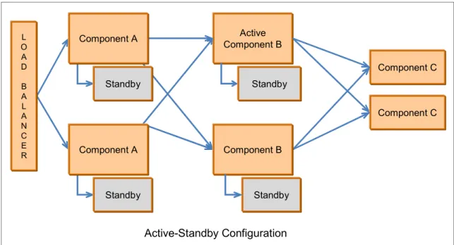
An active-passive deployment (shown in Figure 2-9) uses hot or cold standby components to take over in the event that the main component fails. The standby components often exchange heartbeat information with the active components at a configurable time. If a specific number of heartbeats are missed, the standby component takes over as the active component. Some hardware components can also take over the MAC addresses of the network interface card, which allows network switches and load balancers to function normally without having to change any network behavior.
Figure 2-9 Active-Standby configuration
This model also adds to the cost and is not as popular, because the standby component is often idle and waiting for the active component to fail. This might not be viewed as the best use of resources. This is why active-active
deployments are more common.
Component C Component C Standby Active Component B Active-Standby Configuration L O A D B A L A N C E R Component B Standby Standby Standby Component A Component A
Chapter 3.
Product technologies for
high availability
This chapter describes the product technologies that can be used to build a high availability topology. It discusses hardware clustering concepts and the high availability features of the WebSphere messaging products. This includes multi-instance queue manager and multi-instance broker capabilities, WebSphere MQ clusters, and queue sharing groups on z/OS®.
3.1 High availability and failover
High availability is one of the components that contributes to providing continuous service for the application clients. It ensures that the failure of any component of the solution, either hardware, software, or system management, does not cause the application and its data to become permanently unavailable to users.
Failover of an IT system is the capability to switch over automatically to a standby system upon the failure or abnormal termination of the previously active
application system.
High availability can be achieved by a combination of two technologies:
Hardware clustering (for example, PowerHA cluster)
Software clustering to provide high-service availability (WebSphere MQ with multi-instance queue manager and multi-instance broker) or load balancing (for example, WebSphere MQ cluster)
3.2 Hardware clustering
High-availability clusters are grouped computers in a network that provide high availability for application systems by using hardware redundancy and software monitoring. The cluster is configured with appropriate file systems on shared disk storage, with a heartbeat mechanism to detect a failure on the other system. When a hardware or software failure in the cluster is detected, the application can be restarted on another system.
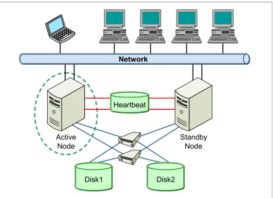
Figure 3-1 on page 35 illustrates a topology where two computers on a network are used as server nodes in a cluster. Client applications can use this network to communicate with the cluster and use the services provided by the highly available cluster. Highly available clusters often build redundancy into a cluster to eliminate single points of failure. For example, multiple network connections are often used and data storage is multiply connected through heartbeat disk storage.
Figure 3-1 Hardware clustering
Highly available clustering uses the concept of resource groups where applications, services IP labels, and even file systems on disk storage are grouped together. When a failure occurs in one of the applications in the group, the entire group is moved to a standby server by the use of cluster services. The heartbeat private network connection is an additional non-IP network. This is a key component used by the cluster to monitor the health and status of each node in the cluster.
The most commonly used highly available cluster is a two node cluster. The two common configurations are:
Active/Active
Traffic intended for the failed node is either passed to an existing node or load balanced across the remaining nodes.
Active/Passive
Provides a fully redundant instance of each node, which is only brought online when its associated primary node fails.
Active Node Standby Node Heartbeat Disk1 Disk2 Network
3.2.1 IBM PowerHA cluster
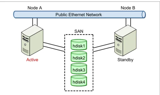
PowerHA for AIX is the IBM high availability solution for POWER® systems running AIX. Versions prior to PowerHA 5.5 are referred to as HACMP. A PowerHA cluster is illustrated in Figure 3-2.
Figure 3-2 PowerHA cluster
High availability and multi-processing components
In addition to providing high availability services, a PowerHA cluster provides multi-processing components (multiple applications running over a number of nodes with shared or concurrent access to the data on shared disk storage). The cluster topology describes the underlying framework: the nodes, networks, and storage, as shown in Figure 3-3 on page 37. PowerHA uses this framework to build up the cluster services to keep the cluster resources (such as the service IP) and application server and file systems highly available.
SAN Power Server Power Server Node A Node B hdisk1 hdisk2 hdisk3 hdisk4