24
Abstract
This paper includes the significant onsite experience of the authors related to problems faced in amine systems with fresh amine and their possible solutions in phases#2&3 of South Pars gas complex. The amine system was designed as a closed circuit system with the primary objective of removing H2S, CO2, and other acidic components from gaseous hydrocarbon streams. Amine plant operational problems such as excessive foaming, intense corrosion and capacity reduction are observed in gas sweetening unit. Heat stable salt (HSS) accumulations were found to be one of the main reasons for corrosions. Since there are no MDEA purification facilities in phase#2&3, it was decided to replace old MDEA solution with fresh MDEA. However, there are some problems that many plants have experienced after amine replacing or construction. In this paper, practical strate-gies with experimental data were proposed to overcome these problems.
Key words:
Amine Replacement, HSS, MDEA, Corrosion, Degradation, RegenerationIntroduction
The amine treating unit is of great importance in gas processing and refinery operations. The amine plant now attracts increasing attention due to high pressure for environmental compliance and quality of H2S and CO2 removal. Two major problems representing a significant threat to an amine gas treating plant are corrosion and instability of operation, resulting in unscheduled upsets and outages [1]. High corrosion rates, typical for a number of amine plants, as well as of stainless steel, usually attributed to chloride, create serious safety concerns. High corrosion leads to high repair costs, potential environmental implications, and lost production. The results of a survey conducted by the National Associa-tion of Corrosion Engineers (NACE) indicate that 60% of total 24 amine plants surveyed experience stress cor-rosion cracking in the amine absorbers [2]. A similar survey by the Japanese Petroleum Institute reported a 72% occurrence of cracking at amine gas treating facilities [2]. Carbon steel corrosion is often attributed to the amine contaminants, which cannot be stripped and thereby accumulate in the amine solution. These contaminants include metals from the unit equipment, specific ions that interfere with the absorption, amine
degradation products and amine by-products in the form of heat stable salts present. These heat stable amine salts in the solution reduce the amount of amine available for gas treatment, thereby reducing the unit’s productivity. Heat stable salts (HSS) also cause corrosion problems and lead to a higher foaming tendency of the solution [3]. Foaming in the absorber columns, higher amine losses, absorber tower pluggage, heat exchanger fouling, shortened amine filter life, and overall unit instability, affect performance of the sulfur recovery unit. Removal of the HSS from the circulating amine will help to improve the performance of the amine unit, decrease maintenance and filter replacement costs, and foaming [4]. Periodic amine clean-ups, either on-site or off-site, ion exchange, vacuum distillation, electro dialysis, and periodic reclaiming, are ways for providing a solution for HSS accumulation [5, 6].
Experimental
Amine plant operational problems, such as excessive foaming, intense corrosion and capacity reduction are observed in gas sweetening unit that lead to amine replacement (fig. 1).
Corrosion
The major problem with the amine unit was corrosion (fig. 2,3).
According to the inspection report, max corrosion rate of gas sweetening unit was 10.5 mpy in 2009, which was a very high corrosion rate compared with to previous years. It is noted that the refinery’s goal is to keep the corrosion rate below 10 mpy. Some samples were taken form used MDEA. Analysis results for these samples are given in Table 1.
Figure 1- Gas Sweetening Unit.
Figure 2- Corrosion sign in reboiler tarin#1
Figure 3- Corrosoin sign in reboiler train#2 Table 1- Old MDEA analyze results in gas train 1, 2
Test Unit Train1 Train2
MDEA wt% 44.9 45
Chloride g/l 0.4 0.2
Sulfate mg/l 41 32
Total Acidity mg KOH/ g sample 3 2.7 H2S as S ppm Trace<1.0 Trace<1.0
H2O mass% 36.6 40.1
Na ppm 51 39
Ca ppm 5.8 5.2
Fe ppm 1.6 3.4
Cr ppm <1.0 <1.0
S2-(W %) Trace Trace Trace
Na+ (W %) 0.2
CO32-(W %) Trace Trace
SO42-(W %) 20.98 41
Flash gas
Operation parameters have shown signs of excessive foaming. Amount of outlet flash gas from flash drum after absorber tower was high and opening of LV0026 (bottom absorber level valve) a sign of flash gas was increased, too. This is clearly shown below (fig.4).
Figure 4- Flash gas form flash drum and LV0026 opening
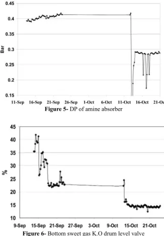
Absorber Differential Pressure (DP)
Before 2009 overhaul absorber DP in gas train was increasing gradually and caused amine carry over from absorber to treated gas K.O drum. This means there is foaming in absorber. Therefore, to prevent risk of tray failure, feed to absorber was reduced in order to meet max allowable DP across the tower. During overhaul lots of scale was found over trays. After overhaul opening of LV0036 (bottom sweet gas K.O drum level valve) a sign of carryover and PDI-0026 (Absorber DP) decreased (fig 5, 6). LV0036 opening reduction shows that amine carryover was reduced after overhaul. These indicate foaming has reduced in amine loop. DP reduction can be related to the cleaning of scales over the tower trays, too. DP of absorber before overhaul reached 0.41 barg and decreased down to 0.28 barg after overhaul and tray cleaning.
H2S of sweet gas
H2S content of sweet gas was whitin acceptable range before amine replacement, but it was high after MDEA replacing because H2S loading of fresh MDEA was considerably higher than that of old MDEA as a result of acid assisted regeneration phenomena. By taking some actions, such regeneration, top temp increasing and amine flow decreasing, sweet gas H2S content dropped back to the spec range (fig7).
H2S loading
After start up of the H2S unit loading of the lean fresh MDEA was considerably higher than old MDEA while all operating parameters were the same as before (Fig.8).
This is a problem many plants have experienced after amine replacing. What is happening is a result of loss of heat stable salts in old amine solution. Actually, the acids that make these salts improve the regeneration of the MDEA because they will preferentially drive off the H2S from the lean amine solution, leading to a lower lean loading than it would get with pure MDEA. This phenomenon is known as “acid assisted regeneration”. (fig.9).
Another reason for high H2S loading can be higher loading CO2 by fresh amine, which can affect the regenerator tower performance and lead to increased H2S loading. As the fresh amine begins to form heat stable amine salts, solvent starts to reach lower and lower lean loadings for the same regeneration conditions. It should just let natural incursion rate of salts solve the problem.
Figure 7- H2S in sweet gas
Figure 8- H2S loading in lean MDEA
Figure 9- HSS lean amine solution in gas sweetening unit
However, there are some actions that have been taken to decrease amine H2S loading. These actions are:
1. Decreasing amine flow rate from 155 down to 140 m3/h
in order to increase MDEA residence time in regenera-tor.
2. Increasing regenerator top temperature set point from 98 to 105 ºC in order to have better amine regeneration and H2S loading decrease.
Figure 10- Amine flow rate in gas sweetening unit
Regenerator Bottom Temperature
In order to prevent formation of primary or secondary amine in MDEA solution, the reboiler temperature shall not rise above 132 oC even for a short time [7],
while according to the trends of reboiler temperature, this value exceeds frequently before amine replacement. This high temperature could be due to the presence of MEG in amine loop. This event is very harmful. Because high temperature can cause amine degradation leading to acid causing corrosion. In fact, heat stable salts are formed when amines react with acidic components other than H2S and CO2 in the inlet gas to the amine absorber. According to the amine expert documents this problem can occur when the salt stability decreases in the point where some disassociations take place in a site specific location in the unit. Corrosion occurs when that disas-sociation creates a corrosion cell with metal in the system. Other problems are caused by chelating effect of some of the organic acids, which are formed. They can hold the iron in solution rather than allowing it to form a
protec-tive film on the metal, resulting in areas of fresh metal where corrosion is more likely [8]. As mentioned, to de-crease amine H2S loading, regenerator top temperature is increased from 98 to 110ºC to improve amine regenera-tion. However, top temperature increase aligns with bot-tom temperature increase. In order to prevent formation of primary or secondary amine in MDEA solution, the reboiler temperature shall not rise above 132oC because
this high temperature leads to amine degradation. Amine degradation products (results of chemical modification of alkanolamines) promote corrosion by complexing iron. That complex iron enhances the corrosion in amine systems in the same manner as HSS. Regenerator bot-tom temperature is kept below 132ºC by amine flow reducing from 155 to 140 m3/h. Lower amine flow rate
increases MDEA residence time in regeneration loop and as a result decreases H2S loading so that it could be possible to decrease top temperature from 110 to 105ºC and consequently bottom temperature to less than 132oC
in order to prevent degradation.
CO2% in Acid Gas to SRU
There was found a high MEG concentration in amine loop in lab tests. After amine replacement in constant amine concentration water was substituted for MEG. So, water content in fresh amine increased. The reaction be-tween the amine and CO2 is a bit more complex because CO2 absorption can occur via two different reaction mechanisms. When dissolved in water, CO2 hydrolyses to form carbonic acid, which in turn slowly dissociates to bicarbonate. The bicarbonate then undertakes an acid-base reaction with the amine to yield the overall reaction (Eq.1-4) shown below:
CO2 + H2O ↔ H2CO3 (Carbonic Acid) (1) H2CO3↔ H+ + HCO
3 (Bicarbonate) (2)
H+ + R
1R2R3N ↔R1R2R3NH (3)
CO2 + H2O + R1R2R3N ↔ R1R2R3N H+ HCO
3 (4)
Tertiary amines must react with CO2 via the slow CO2 hydrolysis mechanism discussed earlier [9]. For MDEA, since the CO2 reaction with water to form bicarbonate is slow while H2S reaction is fast, it is generally felt the H2S reaction is gas phase limited while the CO2 reac-tion is available for CO2 absorption, MDEA products yield significant selectivity toward H2S relative to CO2. It may be possible that water concentration increase in amine helps to increase CO2 reaction with amine. Thus,
CO2 concentration increases in acid gas and is followed by H2S by concentration decrease (Fig12). It has been shown that H2S concentration in acid gas was decreased after amine replacement which can confirm this hypoth esis. Also, this is possibly related to absorption increase with fresh MDEA compare with used MDEA. To de-crease CO2 absorption, it is recommended to change feed tray form 27 to 25.
TSS of lean amine solution
Trends in fig.13 show that Total Suspended Solid (TSS) has been increased after shut down and amine replace-ment. Because during overhaul cleaning and washing of gas sweetening unit equipments and piping were not done due to time limitation. It’s recommended to per form washing before loading new amine and put amine filtration packages in service before gas sweetening unit start up.
Antifoam consumption
After amine replacement, antifoam injection rate was decreased from 11 to 6 Lit/hr. Thus, antifoam consump-tion has decreased considerably with amine replacement.
Results and Discussion
Since amine plant operational problems, excessive foam-ing, and intense corrosion are observed in gas sweetening
Figure 12- H2S concentration in inlet sulfur recovery unit
degradation products (results of chemical modification of alkanolamines) promote corrosion by complexing iron. The complex iron enhances the corrosion in amine systems in the same manner as HSS. Regenerator bot-tom temperature is kept below 132 ºC by amine flow reducing from 155 to 140 m3/h. Lower amine flow rate
increases MDEA residence time in regeneration loop and as a result H2S loading decreases so that it would be possible to decrease top temperature from 110 to 105ºC and consequently bottom temperature less than 132oC in
order to prevent from degradation.
Conclusion
Amine degradation causes the formation of heat stable salts (HSS) that can lead to corrosion. The amine unit performance begins to deteriorate as the HSS level increases and the performance absorber and regenera-tor becomes less stable. Therefore, to overcome this problem, old amine was substituted with fresh amine in phases#2&3 of SPGC. Some useful suggestions can be used in other sweetening plants by replacing amine. One of the most important results of amine replacement is improvement performance of the unit, reduction of antifoam use, and probable decrease of maintenance cost because of severe corrosion. Although installation of a continuously operating HSS reclaimer allows amine plants to ensure consistent reliable gas treating.
lutions, Oil & Gas, Eco-Tec Inc, Canada, 2007.
[5] Simmons C.V., “Reclaiming Used Amine and Glycol
Solutions”, Proceedings of Laurance Reid Gas Condi-tioning Conference Norman, 1991.
[6] Burns D. & George R.A., Proceedings of the 74th
GPA Annual Convention, pp. 95-103.
[7] ELF EP, phase 2&3 gas sweetening unit-operating guidelines, South pars gas field development, Paris, 1998.
[8] Sheilan M.H., Spooner B.H., E.street D. & van Hoom E., Amine Treating and sour water stripping, amine expert Inc, 2005.
[9] Cummings A.L., Veatch F.C. & Keller A.E., Cor-rosion and corCor-rosion control methods in amine system containing H2S, 1000 South Pine Ponca City, Oklahoma, 2008.
[10] Verma N. & Verma A., Amine system problems arising from heat stable salts and solutions to improve
system performance, Saudi Aramco, Udhailiyah -31311,