T
HROTTLE
A
CTUATOR
C
ONTROLLER
F
OR
A
UTOMOTIVE
A
PPLICATIONS
(S
IMULATION
S
TUDY
)
N. H. Othman,
aK. B. Tawi
a,*, B. Supriyo,
bM. Salman Che Kob,
aI. I. Mazali,
aM. Sabri Che Kob,
aa
Faculty of Mechanical Engineering, Universiti Teknologi Malaysia,
81310 UTM Skudai, Johor.
b
Electronic Engineering Department,
Politeknik Negeri Semarang, Indonesia.
Article history Received 30 May 2015 Received in revised form
23 July 2015 Accepted 26 August 2015
*Corresponding author
[email protected]
K
EYWORDSThrottle Actuator Controller; PID Controller;
Ziegler-Nichols Method; Astrom-Hagglund
relay feedback Method
I
NTRODUCTIONThrottle is the mechanism by which the flow of a fluid is managed by opening and closing the valve.
This throttle body is mounted in the engine and used to control engine power by regulating the amount of airflow into the engine’s combustion chamber. In driving situation, the throttle valve is connected to the accelerator paddle, controlled by the driver through mechanical linkage which enables the driver to control the speed of the car [1].
Recent advance technologies have enabled the throttle valve to be operated by electric actuator and control system. Having an ability to control the opening plate automatically helps to control the amount of air that enters the combustion engine [2]. Hence, the air flow rate will directly control the torque output of the engine, and consequently the speed will be raised or lowered according to the demand.
There are many types of control system that can be used to control the throttle valve opening. One type of control system used in this project is by using PID (Proportional, Integral, and Derivative) controllers. PID controller is the most popular feedback controller that frequently used in process industries because it is robust, easy to understand and provides excellent control performance [3]. PID is used in a wide range of applications such as process control, motor drives and automotive.
Throttle controller is used for controlling the position of the valve opening and closing. Basically, this automobile technology is connected straight from the throttle to the accelerator paddle. However, in this study, it was electrically connected from the throttle to the accelerator paddle by using the throttle actuator test rig developed by Drivetrain Research Group (DRG) at
A
BSTRACTUniversity Teknologi Malaysia (UTM). As main components, a DC motor was installed with throttle actuator test rig as an actuator to move the system, and a linear actuator as the controller of the accelerator paddle.
In this project, the throttle actuator was used for the purpose of controlling the position of the throttle. Matlab SIMULINK was used to design the PC based controller for the throttle actuator controller system. The performance of this mechanism was then compared with the performance of different type of controller and in term of steady state error.
T
HROTTLEA
CTUATORM
ECHANISMThere are many components that are related to throttle actuator system. All the components that had been chosen represent the actual throttle system and had been simplified their complexity for easier understanding and utilization.
A common throttle actuator consists of DC motor, spur gears, return spring and position sensor. In this study, the throttle actuator system was equipped with DC motor as the actuator of the system. The DC motor was connected to the throttle plate via gear unit [4], which is also called gear reducer. The gear reducer functioned as speed reducer, torque multiplier and power screw mechanism [3] for pulling the throttle plate angle axially.
S
YSTEMM
ODELLINGThis section describes mathematically how the throttle actuator controller had been modelled.
Modelling of DC Motor
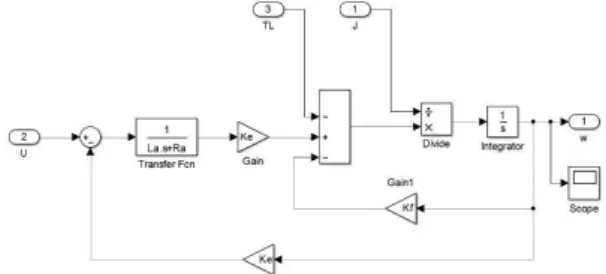
Figure 1 shows the DC motor Simulink Model. The DC motor was modelled by using Laplace operator s = d/dt, as follows:
Va = sLaia + Raia + Kaω (1)
Va – Kaω = sLaia + Raia (2)
Tm – TL =Jm.s.ω + Bm.s2.ω (3)
θ = sω (4)
Figure 1: Simulink Model of DC Motor
Gear Reducer
The function of a gear reducer is to reduce the speed of the throttle actuator system and as a torque multiplier. The input speed from a DC motor shaft is reduced via gear reducer which is connected to the output to the power screw mechanism for shifting the throttle plate angle in axially motion. The ratio of the gear reducer in this study was 5:1, where the speed would be reduced about five times slower compared to the input speed.Power Screw Mechanism
Power screw mechanism is a mechanism used to change angular motion into linear motion [5]. Reverse mechanism also can be done, by converting input linear motion into rotary motion as the output of the mechanism [6]. It converts every 360° of rotation into 5 millimeters of translation motion. Gear reducer and power screw mechanism are combined to help the motor in providing significant torque to turn the power screw [3], and the required torque of power screw mechanism (Figure 2) for both raising and lowering the load must be considered for this type of throttle actuator system. Torque for raising load is calculated as: ) ( 2 ) ( L d L d d F T m m m R (5)Torque for lowering load is calculated as: ) ( 2 ) ( L d L d d F T m m m R (6)
P
ROPOSEDC
ONTROLLERIn this study, a PID controller was used to control the set point of the throttle actuator to the optimum level. Besides, the controller helped in reducing the error in the simulation. The PID controller was placed before the plant so that it could control the input into the plant, which consisted of DC motor, gear reducer, power screw mechanism and the throttle (Figure 3). The input and the output from the system would give the set point error and that error would be controlled by the PID controller.
Figure 3: Block Diagram of PID Controller
Tuning PID Controller
The objective of applying tuning is to determine the suitable value of three parameters, which were Kp, Kd and Ki, to determine which could be the best PID controller. Before this initial PID parameter is determined, its variables must be obtained first by using Astrom-Hagglund relay-feedback method. By putting the relay block in the controller, a graph can be plotted to obtain the variables for PID parameter which are critical period of waveform oscillation, TC, amplitude of relay output, d and amplitude of waveform oscillation, a.
Figure 4: Result of Relay Feedback Controller
Based on Figure 4, all the variables values can be determine and the critical gain, KC also can be derived as follows:
a d Kc
4
(7)
By using Equation (7), the critical gain was found to be 1.018. By obtaining these two values (KC and TC), the PID parameters (Kp, Ti and Td) in Table 1 could be specified using Ziegler-Nichols formula.
Table 1: Ziegler-Nichols Parameter Tuning
Kp Ti Td
PID 0.6Kc 0.5Tc 0.125Tc
Manual Fine-Tuning Method
Manual fine-tuning is done to obtain the best performance of PID controllers. For simulation, the PID parameter was tuned from the value of Ziegler-Nichols PID parameter. Trial and error method was done to get the best performance PID parameter of the throttle actuator system as shown in Table 2.
Table 2: Best PID parameter
Kp Ki Kd
PID 0.245 0.015 0.0135
Simulation Study
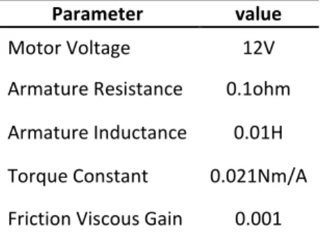
Simulation studies of the proposed PID controller were carried out in order to investigate the performance of the throttle actuator controller in terms of overshoot and steady-state error. The parameters for the DC motor are shown in Table 3.
Table 3: DC Motor Parameter
Parameter value
Motor Voltage 12V
Armature Resistance 0.1ohm
Armature Inductance 0.01H
Torque Constant 0.021Nm/A
Friction Viscous Gain 0.001
After all the Simulink block diagrams (Figure 5) of the DC motor, gear reducer, power screw mechanism and throttle had been completed, the blocks were combined to be one Simulink block model of throttle actuator controller.
Figure 5: Complete Model Simulink Block Diagram of Throttle Actuator Controller
From the simulation result for each setting position, all of the set points were then compared in terms of overshoot and steady-state error. The best set point should contain less both overshoot and steady-state error.
The controllers used in this simulation study were P, PD and PID controllers. From simulation of each controller, the best controller performance would be chosen for the next different set point of the throttle angle in terms of steady-state error and overshoot. To obtain the best PID controller parameters, the set point of the throttle plate was set to be 45°. Therefore, all parameters values were based on this set point because during tuning the best PID parameters, the 45° set point had been already used.
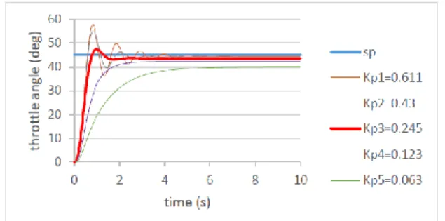
Figure 6: Controller performance with several Kp gains
From Figure 6 above, the highest value of Kp gain was 0.611, which was also the initial value of the gain. From this gain value, the performance of the controller was found very unstable compared to the other Kp gains, where the percent overshoot of this Kp gain was 28.04% but it exhibited the lowest steady-state error of about 1.28%. The lowest Kp gain was 0.063, which showed no overshoot detection and exhibited the highest steady-state error of 11.14%. The best Kp gain value for P controller performance was 0.245. Although it had steady-state error of 3.11%, this
Kp gain showed the most stable performance, in which the overshoot of the controller was only 5.22% from the set point.
Figure 7 shows the simulation performance of PD controller. As the value of Kp gain was constant, various Kd gains were used to achieve the desired result. The initial gain value of Kd was 0.27 and exhibited no overshoot although the controller performance was stable with the percent steady-state error of 3.19%. The lowest Kd gain used was 0.0034, whose overshoot percentage was the highest among the other gain, which was about 3.25% of throttle opening.
Figure 7: PD Controller Performance with Several of Kd Gain and Constant Kp Gain
The best Kd gain value for this PD controller was 0.0135, whose overshoot was the lowest percentage among the other Kd gains, which produced 1.43% and obtained similar percentages of steady-state error of 3.11%.
Figure 8: PID Controller Performance with Several Ki Gains and Constant Kp and Kd Gain
to the set point and its error was only 0.24; almost equal to zero in steady-state error of the set point of throttle actuator controller.
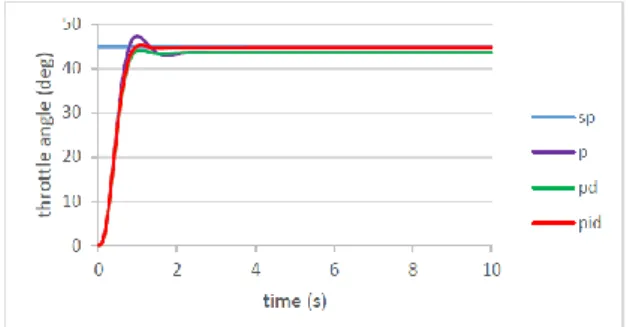
Figure 9 shows the performance for each controller where the best gain value was used in the simulation. For P controller, the best Kp gain reduced the overshooting but increased in steady-state error compared to other controllers. For PD controller, the overshoot of the controller performance had been reduced less than the set point, and the steady-state error also had decreased.
Figure 9: Best Performance for P, PD, PID Controller
The performance of the controller almost achieved the desired output when the PID controller was used, whose steady-state error was eliminated. For this PID controller, all the best gain values for each controller were used.
sp = 10º sp = 30º sp = 50º sp = 70º sp = 90º
Figure 10: Performance of the PID Controller for Each Set Point
Figure 10 shows the performance at each set point of throttle opening using the best PID controller. Almost all set points reached the desired result, where the steady-state error was nearly zero and there was low overshooting position of the throttle opening.
C
ONCLUSIONThe main function of this simulation study is to access the performance of the throttle actuator controller in term of steady-state error. In term of controller’s performance, PID controller gives the better result compared to P and PD controller, whose results would be more accurate as the
desired input if the PID parameters are finely tuned. To obtain the initial PID parameters, two methods have been conducted, which are the combination of Astrom-Hagglund relay-feedback method and Ziegler-Nichols methods. From these two methods, many variables of the PID parameters can be extracted to determine the parameters.
N
OMENCLATUREVa Motor Voltage [V] La Motor Inductance [H] ia Motor Current [A] Ra Motor Resistance [Ω]
Ka Back emf constant [mV/ (rad/sec)] ω Motor shaft angular velocity [rad/sec]
Angular displacement [rad]
Tm Motor Torque [Nm]
KT Torque Constant [Nm/A] TL Toque Lowering the Load [Nm] TR Toque Raising the Load [Nm]
Jm Total load and motor Inertia [Nm.sec2] Bm Viscous friction coefficient [Nm/
(rad/sec)]
dm mean diameter of power screw (0.0455 [m]) [5]
F Axial compressive force [N]
µ Friction of power screw surface contact (0.15) [7]
L power screw pitch (0.005 m)
R
EFERENCES[1] Song, J. and Byung, K., 1999.Throttle actuator control system for vehicle traction control. Mechatronics 9. 477-495.
[2]Al-Samarraie, S.A. and Abbas, Y.K., 2012. Design of
Electronic Throttle Valve Position Control System using Nonlinear PID Controller. International Journal of Computer Applications. 59.
[3]Supriyo, B., and Tawi, K.B., 2006. Position Control for
Pulley Axial Movement of Electro-Mechanical Dual Acting Pulley Continuously Variable Transmission System. Jurnal Mekanikal. No. 22. 89-102.
[4]Markus, R., and Horn, M., 2011. Robust Position
Control of an Electromechanical Actuator for Automotive Application. World Academy of Science, Engineering and Technology 59.
[5]Budynas, R.G. and Nisbett, J.K. Shigley’s Mechanical
Engineering Design. (9th Ed. in SI units). New York: Mc Graw Hill.
[6] February 1999. Power Screw, Chapter 15. Mechanical Design Data Manual.
[7] “Frictional Coefficients for some Common Materials
and Materials Combinations." from