PRODUCTION OF CATHODE MATERIAL FOR OXYGEN
ELECTRODES BY ANODIC OXIDIZATION OF MULTIWALL
CARBON NANOTUBES
M.O. Danilov
[a],*, I.A. Rusetskii
[a], I.A. Slobodyanyuk
[a], O.Y. Khyzhun
[b],
G.Ya. Kolbasov
[a]Keywords: Anodic oxidation of carbon nanotubes, Graphene oxide, Electrode materials, Oxygen electrode.
We report the synthesis of graphene oxide by the electrochemical method. The standard redox potentials of the carboxyl groups of carbon is used to select the oxidation potential. Graphene oxide obtained by anodic oxidation of multiwall carbon nanotubes in concentrated sulfuric acid, confirmed by electron microscopy, XRD, X-ray photoelectron spectroscopy, X-ray emission spectroscopy and Raman spectra, is a prospective electrode material for the chemical current sources. The oxidation potential in 96 % sulfuric acid is +3 V and the time of oxidation was 4 h. A good electrical conductivity is observed because of the presence of fragments of carbon nanotube in graphene oxide. Thus, this material is a very promising electrode material for oxygen electrodes. The current–voltage characteristics of the oxygen electrodes, based on electrochemically produced graphene oxide, is the graphene oxide produced by anodic oxidation of multiwall carbon nanotubes.
*Corresponding Author:
E-Mail: [email protected]
[a] Vernadskii Institute of General and Inorganic Chemistry, National Academy of Science of Ukraine, 32–34 Palladin Avenue, 03680 Kyiv, Ukraine.
[b] Frantsevych Institute for Problems of Materials Science, National Academy of Sciences of Ukraine, 3 Krzhyzhanivsky Street, 03142 Kyiv, Ukraine.
Introduction
Application of air or oxygen electrodes in devices generating electrical energy is useful; such application does cause environmental problems and allows to save nonrenewable natural resources. The air and oxygen electrode is a three-phase electrode–electrolyte–gas system, where the generation of electric current is localized at a phase boundary. The current magnitude generated at such gas diffusion electrode depends on the triple contact zone of these three phases. In its turn, the electrode itself is composed of catalyst and carrier. The interaction between them determines the quantity of generated current, which depends on catalyst being used. It is known that the most effective catalyst for oxygen recovery is platinum, which is a very expensive material. A great number of workers is forced to study other effective but less expensive catalysts.1
Another problem is catalytically active and stable carrier. The benefits of carbon nanotubes used as the carrier are shown. 2–4 Presently, a series of stuies have been reported
using graphene as an electrode material for lithium-ionic accumulators5 and also as a catalyst carrier for catalysts in
fuel cells.6–10
At the moment the methods known for the synthesis of graphene from carbon nanotubes are:11 intercalation of
alkaline earth elements and nitrogen; plasma etching; microwave unzipping; unzipping by catalytic metal nanoparticles; ultrasonic unzipping; opening-up by laser irradiation; electrical unzipping; hydrogenating at the
high-temperature; unzipping by influence of a scanning tunneling microscope; electrochemical unrolling; the redox chemical synthesis. Among most technologically advanced methods, in our opinion, electrochemical process is paid much attention because it has the ability to control the process by changing three parameters: voltage, current, and time of this process.
Although extensive studies have been performed to obtain graphene nanosheets via electrochemical exfoliation of graphite,12 Pillai and his group are unique who suggested
that in aqueous electrolytes using electrochemical oxidizing and reducing, longitudinal splitting and unzipping single13
and multiwall carbon nanotubes (MWNTs)14 are possible to
be synthesized. According to Pillai, inducing electric field at the phase boundary results in the cleavage of carbon-carbon, similar to the mechanism of oxidation of olefin to the diol,15,16 by forming the complex manganese ester.17,18
Further, the diol is oxidized to form keto groups and complete rupture of the C = C bonds. Experimental studies,19 as well as results obtained by Tour and
co-workers20–22 have shown that the unzipping of MWCNTs is
most likely due to the intercalation of oxidized molecules in the defects in multi-walled carbon nanotubes.
Formation of surface groups on highly oriented pyrolytic graphite (HOPG) by electrochemical oxidation and intercalation acid anions is described.23–27 Electro oxidation
mechanism was studied in sulfuric acid, and it shows the formation of alcohol and other functional groups on the basal plane of HOPG surface.25 As a result of oxidation, the
surface was hydrophilic for its nature.28 This phenomenon
has been useful for the dispersion of graphene oxide (GO) in deionized water.29 The use of sulfuric acid leads to a strong
oxidation of graphene surfaces to form thin sheets with a large number of the structure defects.30 High resistivity of
graphene oxide is due to defects caused by damages of sp2
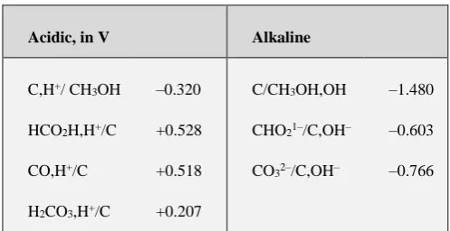
Graphene is usually obtained as a mixture of mono-, bi- and multilayer (3 – 10 monolayers) structured irregular flakes or plane sheets.32 Based on the standard redox
potentials of carbon33 (Table 1) the required oxidant
potential in acidic medium should be higher than + 0.528 V.
Table 1. Oxidant potentials in acidic and alkaline mediums
Acidic, in V Alkaline
C,H+/ CH 3OH
HCO2H,H+/C
CO,H+/C
H2CO3,H+/C
–0.320
+0.528
+0.518
+0.207
C/CH3OH,OH
CHO21–/C,OH–
CO32–/C,OH–
–1.480
–0.603
–0.766
At the electrochemical oxidation of multi-walled carbon nanotube, electrode potential is more electropositive because of the polarization of the electrode-collector material, the ohmic losses in the MWCNT and kinetic difficulties. This is confirmed by experimental data on the oxidation of MWCNTs in sulfuric acid at potentials between 0.7 and 4.8 V relative to the silver-chloride electrode.34 In a
review,19 numerous works on the anodic oxidation of
different forms of carbon in sulfuric acid at electrodes of various materials at a voltage of 1 to 10 V are discussed. Based on analysis of existing literature data, the possibility of obtaining the graphene oxide by anodic oxidation of multi-walled carbon nanotubes, to the best of our knowledge, has not been attempted as yet.
Based on the above studies it is clear that there is no consensus on the possibility of obtaining the graphene oxide by anodic oxidation of multi-walled carbon nanotubes. Therefore, the aim of this study was to investigate the possibility of obtaining graphene oxide, using carbon nanotubes as a starting material, by simple technology method for the production of the electrode material for the oxygen electrodes of the fuel cells.
Experimental
For the electrochemical production of graphene oxide, multi-walled carbon nanotubes were used. The outer diameter of MWCNTs was about 10 – 30 nm, the specific surface area was 230 m2 g–1, with a bulk density of 25 – 35 g
dm–3. The number of walls ranges from 8 to 15. Anodic oxidation of carbon nanotubes was conducted in a 150 ml glass beaker containing 96 % sulfuric acid solution, the weight of MWCNT was 1 g. The container for the oxidation of MWCNT is a bag that served as a membrane in lead accumulators, which is stable in acid, is used. For the firmly pressed MWCNTs to the anode electrodes, PTFE liners were used. Titanium and platinum electrodes are used as cathodes and the anodes respectively. Oxidation of carbon nanotubes was carried out in the galvanostatic mode. A silver-chloride electrode connected through a salt bridge was used as a reference electrode. The samples of graphene oxide (GO) obtained by the electrochemical oxidation of the
carbon nanotubes were examined with a JEM–100 CXII electron microscope. The X-ray phase analysis was performed using a DRON–4 X-ray diffractometer employing CuKα irradiation. Raman spectra of initial
MWCNTs and GO were registered by INVIA Raman microscope (Renishaw) under the excitation of He-Ne laser with ex = 0.6328 Å. The position of standard Si sample at
520 cm–1 was used as the reference for wavenumber calibration. WiRE 3.4 software was used for Raman data acquisition and data analysis. The presence of oxygen-containing groups in graphene oxide was analyzed employing the X-ray photoelectron spectroscopy (XPS) method. The XPS spectra of graphene oxide and, for comparison, pristine multiwall carbon nanotubes (MWCNTs) were recorded using the UHV-Analysis-System designed and assembled by SPECS Surface Nano Analysis Company (Berlin, Germany). The UHV-Analysis-System is supplied with a hemispherical PHOIBOS 150 analyzer. The XPS spectra of the graphene oxide and MWCNTs were recorded in an ion-pumped chamber at a base pressure less than 8 10–10 mbar. The XPS spectra of the above mentioned carbon materials were excited by a MgK source of X-ray irradiation (E = 1253.6 eV) and were measured at a constant pass energy of 30 eV. Furthermore, the X-ray emission spectroscopy (XES) method is recognized as a very powerful technique when studying carbon materials35,36
by measuring the XES CK band, which represents the energy distribution of the C 2p states. Technique of recording the XES CK band (K LII,III transition) was
similar to that described.37 Briefly, the XES CK bands of
graphene oxide and MWCNTs were acquired employing an RSM–500 spectrometer-monochromator equipped with a diffraction grating (600 groves / mm, radius of curvature of
R = 6026 mm). Secondary electron multiplier VEU–6 with a CsI photocathode was used as a detector. Working condition of a spectrometer electron gun when exciting the XES CK
bands was set as follows: Ua = 5.0 kV and Ia = 2.2 mA.
Energy resolution of the RSM–500 spectrometer was evaluated to be 0.25 eV when measuring the XES CK
bands of graphene oxide and MWCNTs.
The synthesized materials were prepared by pressing two-layer oxygen electrodes. The hydrophobic two-layer contained 0.07 g / cm2 acetylene black with 25 %
polytetrafluoroethylene, and the active layer contained 0.02 g / cm2 RGO, with 5 % polytetrafluoroethylene. The
studies were carried out on a fuel cell mockup, a zinc electrode being used as the anode. A mockup for the testing of gas-diffusion electrodes is described.38 The electrolyte
was a 6 M KOH solution. . A silver-chloride electrode connected through a salt bridge was used as a reference electrode. The electrochemical characteristics were recorded under galvanostatic conditions. The oxygen source was a U-shaped electrolyzer with alkaline electrolyte. Oxygen was supplied to the gas electrodes under an excess pressure of 0.01 MPa. Before measurements, the oxygen electrode was blown through with oxygen over an hour.
The characteristics of the oxygen electrode from the electrode materials obtained by the anodic oxidations of carbon nanotubes were compared with the characteristics of electrodes from the initial MWCNT with deposited platinum black. Platinum is deposited by electrochemical method from an aqueous solution containing 3 % H2PtCl6 and 0.2 %
Results and Discussion
We investigated the dependence of the electrochemical characteristics of oxygen electrodes based on the GO obtained by the oxidation of MWCNTs with various time. Anodic oxidation of MWCNT was performed at a potential + 3 V over 1.5, 4, and 5 h. As can be seen from the current– voltage curves plotted for the oxygen electrode (Figure 1), increasing the anodic oxidation time to 4 hours leads to increase of the electrochemical characteristics of the electrodes (Curve 2). With further increase of the time of oxidation the characteristics do not vary significantly (Curve 3).
Figure 1. Dependence of potential on current density for oxygen electrodes with the active layer in an amount of 0.02 g / cm2
consisting of graphene oxide prepared by electrochemical oxidation of MWCNTs at the potential + 3 V with different oxidation time: (1) 1.5, (2) 4 and (3) 5 h.
We have also carried out the oxidation of MWCNTs at the different potentials over 4 hours. Potential ranged from + 1.8 V to + 4.5 V. As shown in Figure 2, the anodic oxidation of multiwalled carbon nanotubes over 4 h at the potential of + 3.0 V produces the most catalytically active materials for oxygen electrode.
Figure 2. Dependence of potential on current density for oxygen electrodes with the active layer in an amount of 0.02 g / cm2
consisting of the graphene oxide prepared by electrochemical oxidation of MWNTs at various potentials (V): (1) initial MWCNTs, (2) + 1.8, (3) + 4.5, (4) + 2.5, and (5) + 3.0 V.
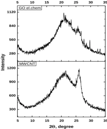
Materials obtained by anodic oxidation of MWCNTs were investigated by means of various physical and chemical methods. Figure 3 shows the XRD analysis of the obtained samples.
Figure 3. XRD patterns of the samples of initial MWCNTs (MWCNT, bottom panel) and graphene oxide (GO el.chem, upper panel) obtained by electrochemical oxidation of the multi-walled carbon nanotubes.
As one can see from the micrograph presented in Figure 4a, employing the anodic oxidation of carbon nanotubes, we have obtained samples of graphene oxide. Closely spaced tags of the carbon atoms in the diffraction ring, Figure 4b, show that the obtained sample consists of undulating planar multilayer’s of graphene oxide. The case of obtaining such graphene is reported. 32 From micrographs,
number of layers of graphene oxide was estimated that ranges from 3 to 10. Also, there are fragments of the original multi-walled carbon nanotubes into graphene oxide, which leads to good electrical conductivity of received materials, as opposed to pure graphene oxide. This is evidenced by good electrochemical characteristics of oxygen electrodes obtained in the present work based on graphene oxide (Figures 1 and 2). Figure 5 shows Raman spectra obtained at 633 nm and intensity of 50 % for the graphene oxide prepared by anodic oxidation of MWCNTs in the acidic medium. Analysis of Raman spectra confirms the presence of graphene oxide multilayers.
a b
Figure 4. (a) Electron micrograph of graphene oxide obtained by anodic oxidation of MWCNTs, and (b) the diffraction of this sample
-0.8
-0.6
-0.4
-0.2
0
0 200 400 600
Current density/ mA cm-2
Po
tentia
l (V)
1 2 3 4 5
5 1 / n m
5 1 / n m
1
23 4 5
6 7 8
5 10 15 20 25 30 35
300 600 900 1200 280 560 840 1120
5 10 15 20 25 30 35
MWCNT
In
ten
si
ty
2, degree
Figures 4a and b show an electron micrograph of graphene oxide obtained by electrochemical oxidation of carbon nanotubes and the diffraction of this sample, respectively.
Figure 5. Raman spectra obtained at 633 nm and intensity of 50 % for graphene oxide (GO el.chem, bottom panel) obtained by anodic oxidation of MWNTs and initial MWCNTs (MWCNT, upper panel).
Figure 6 presents the XPS spectra of the graphene oxide and MWCNTs under study. Results of the present XPS measurements indicate that the surface of the pristine MWCNTs reveals the presence of oxygen, with the binding energy of the O 1s core level electrons that is equal to 531.9 eV. This binding energy value corresponds to oxygen-containing species adsorbed on the MWCNTs surface due to exposure of the specimen to air for a long time (several weeks). When going from MWCNTs to graphene oxide, the relative intensity of the XPS O1s core-level spectrum
increases (Figure 6) and its binding energy decreases by about 0.5 eV (Figure 7). The later effect can be explained by the fact that the XPS O 1s core-level spectrum of graphene oxide is a superposition of the spectra of oxygen belonging to adsorbed oxygen-containing species and of oxygen binding with graphene. The precise measurements of the XPS C 1s core-level spectra (Figure 7a) allow for concluding that the maxima of the spectra coincide within accuracy of the present measurements ( 0.05 eV) for the both samples under study. Furthermore, it is worth mentioning that binding energies of the maxima of the XPS C1s core-level spectra of the graphene oxide and MWCNTs,
as it is evidenced from Figure 7a, are close to that of graphite, namely 284.4 eV.39
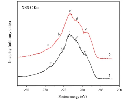
Figure 8 presents the XES CK bands measured for graphene oxide and MWCNTs. It has been reported40,41 that
in the high-energy portion of the XES С K band of MWSNTs the π- and π+σ-binding states are positioned.
These states correspond to the fine-structure peculiarities labeled as “с”, “d”, “е” of the XES СK band that are well resolved for the both samples under study (Figure 8). The mentioned states represent the energy distribution of the C2p
states involved in the mixed ррσ+ / ррπ and pure ррπ
interactions40 in the radial planes and along the axis of
Figure 6. Survey XPS spectra of (1) MWCNTs and (2) graphene oxide.
Figure 7. Detailed XPS (a) C 1s and (b) O 1s core-levels spectra of (1) MWCNTs and (2) graphene oxide
MWCNTs, respectively.40,41 It is worth indicating that the
XES С K band derived in the present work for MWCNTs, by its shape and energy positions of the fine-structure peculiarities, resembles the similar bands recorded in Ref.41
for 200-walled nanotubes with a diameter of 140 nm and double-walled nanotubes with a diameter of 4 nm obtained in arc discharge without catalysts by MER-corporation. In the latter work, it has been established that the bandwidth of the СK band of double-walled carbon nanotubes reduces in comparison with that of the 200-walled carbon nanotubes only near the band maximum (at I > 0.75 Imax).
0 1000 2000 3000
0 2700 5400 8100 108000 1600 3200 4800
64000 1000 2000 3000
In
ten
si
ty
Raman shift, cm-1
GO-el.chem MWCNT
1000 800 600 400 200 0
C KLL O KLL
O 1s
C 1s C 1s
O KLL
In
te
n
si
ty
(a
rb
itra
ry
u
n
its)
Binding energy (eV) C KLL
O 1s
1 2
540 535 530 525 520
2500 3000 3500 4000 4500 5000 5500 6000 6500
N
o
rma
li
ze
d
XPS
in
te
n
si
ty
(cp
s)
Binding energy (eV) O 1s
1 2
(b)
300 295 290 285 280 275 270
0 5000 10000 15000 20000 25000
N
o
rma
li
ze
d
XPS
in
te
n
si
ty
(cp
s)
Binding energy (eV) C 1s
1 2
.
Figure 8. The XES CK bands of (1) MWCNTs and (2) graphene oxide.
This effect is explained in Ref.41 as a result of a decrease
of the π+σ-overlapping in the radial plane inside the
200-walled carbon nanotubes with an increase in diameter of every following wall. As a consequence, the C 2p states involved in such bonds shift toward higher photon energies.41
As can be seen from Figure 8, when going from MWCNTs to graphene oxide synthesized in the present work, visible changes occur in the shape of the XES CK
band. In particular, the sub-band “e” of the XES СK band appearing due to the existence of the C 2p states involved in pure ррπ interactions increases its width in graphene oxide. Furthermore, the maximum “с” of the XES СK band, where mixed ррσ+ / ррπ interactions are located, becomes
narrower when going from MWCNTs to graphene oxide.
Figure 9. Dependence of potential on current density for oxygen electrodes with the active layer in an amount of 0.02 g / cm2
consisting of: (1) initial MWCNTs; (2) graphene oxide produced by oxidation of MWCNTs in sulfuric acid for 4 h at an anode potential of + 3.0; (3) MWCNTs with deposited platinum in an amount of 10 wt. %.
Figure 9 shows the comparative characteristics of the oxygen electrodes on the basis of initial MWCNTs (Curve 1), graphene oxide obtained by electrochemical oxidation of MWCNTs (Curve 2) and MWNTs with deposited platinum (curve 3). As one can see from Figure 9, the electrocatalytic characteristics of electrodes based on graphene oxide are close to the characteristics of electrodes based on platinum-containing materials. All examined graphene oxide materials were stable within six months when being tested in the galvanostatic regime in the fuel-element mockup at a current density of 200 mA / cm2 at oxygen electrodes.
Based on these results, we can conclude that using anodic electrochemical oxidation of multi-walled carbon nanotubes over 4 h in electrolyte of 96 % sulfuric acid at a potential of + 3 V, graphene oxide can be synthesized.
Conclusion
Graphene oxide was synthesized in the present work by anodic oxidation of multi-walled carbon nanotubes. We have determined that the most appropriate conditions for such a synthesis are as follows: oxidation potential in 96 % sulfuric acid is + 3 V and the oxidation duration is 4 h. The formation of well defined graphene oxide was confirmed by data of electron microscopy, X-ray diffraction, X-ray photoelectron spectroscopy, X-ray emission spectroscopy and Raman spectra. In particular, comparative XPS studies of graphene oxide and MWCNTs indicate that the surface of pristine MWCNTs reveals the presence of oxygen, with the binding energy that corresponds to oxygen-containing species adsorbed on the MWCNTs surface due to exposure of the specimen to air for a long time (several weeks). Our XPS data reveal that when going from MWCNTs to graphene oxide, the XPS O 1s core-level binding energy decreases by about 0.5 eV that can be explained by the fact that the XPS O 1s spectrum of graphene oxide is a superposition of the spectra of oxygen belonging to adsorbed oxygen-containing species and of oxygen binding with graphene. The maxima of the XPS C 1s core-level spectra coincide within accuracy of the present measurements ( 0.05 eV) for graphene oxide and MWCNTs under study. However, when going from MWCNTs to graphene oxide, visible changes occur in the shape of the XES CK band, representing the energy distribution of the C 2p states. In particular, the high-energy sub-band appearing due to the existence of the C 2p states involved in pure ррπ interactions increases its width in graphene oxide, while the main maximum of the XES СK
band, where mixed ррσ+ / ррπ states are located, becomes
narrower when going from MWCNTs to graphene oxide. Furthermore, due to the presence of fragments of carbon nanotubes in graphene oxide synthesized, the latter reveals good electrical conductivity. Therefore, this material is expected to be a very promising electrode material for oxygen electrodes of power sources.
Acknowledgement
This paper has been presented at the 4th International Conference “Nanotechnologies”, October 24 – 27, 2016, Tbilisi, Georgia (Nano – 2016).
265 270 275 280 285 290
e e
d d
c c
b b
a
In
ten
si
ty
(
arb
it
rary
u
n
it
s)
Photon energy (eV) a
XES C K
References
1Bidault, F., Brett, D. J. L., Middleton, P. H., Brandon, N. P., J.
Power Sources, 2009, 187, 39.
2Soehn, M., Lebert, M., Wirth, T., Hofmann, S., Nicoloso, N., J.
Power Sources, 2008, 176, 494.
3Hsieh, C-T., Lin, J-Yi., Wei, J.-L., Int. J. Hydrogen Energy, 2009, 34, 685.
4Wang, X., Waje, M., Yan, Y., Electrochem. Solid-State Lett., 2005,
8, A42.
5Wang, G., Shen, X., Yao, J., Park, J., Сarbon, 2009, 47, 2049.
6Xin, Y., Liu, J., Jie, X., Liu, W., Liu, F., Yin, Y., Gu, J., Zou, Z.,
Electrochim. Acta, 2012, 60, 354.
7Lin, Z., Waller, G., Liu, Y., Liu, M., Wong, C. P., Adv. Energy
Mater., 2012, 2, 884.
8Qu, L. T., Liu, Y., Baek, J. B., Dai, L. M., ACS Nano, 2010, 4,
1321.
9Lin, Z. Y., Song, M. K., Ding, Y., Liu, Y., Liu, M. L., Wong, C.
P. , Phys. Chem. Chem. Phys., 2012, 14, 3381.
10Shao, Y., Zhang, S., Wang, C., Nie, Z., Liu, J., Wang, Y., Lin, Y.,
J. Power Sources, 2010, 195, 4600.
11Danilov, M. O., Slobodyanyuk, I. A., Rusetskii, I. A., Kolbasov,
G. Ya., in: Aliofkhazraei, M., Ali, N., Milne, W. I., Ozkan, C. S., Mitura, S., Gervasoni J. L. (Eds.), Graphene Science
Handbook. Fabrication Methods, CRC Press/Taylor &
Francis, 2016, 205.
12Low, C. T. J., Walsh, F. C., Chakrabarti, M. H., Hashim, M. A.,
Hussain, M. A., Carbon, 2013, 54, 1.
13John, R., Shinde, D. B., Liu, L., Ding, F., Xu, Z., Vijayan, C.,
Pillai, V. K., Pradeep, T., ACS Nano, 2014, 8, 234.
14Shinde, D. B., Debgupta, J., Kushwaha, A., Aslam, M., Pillai, V.
K., J. Am. Chem. Soc., 2011, 133, 4168.
15Waters, W. A., Quart. Rev. Chem. Soc., 1958, 12, 277.
16Ohloff, G ., Giersch, W., Angew. Chem., Int. Ed. Engl., 1973, 12,
401.
17Kosynkin, D. V., Higginbotham, A. L., Sinitskii, A., Lomeda1, J.
R., Dimiev, A., Price, B. K., Tour, J. M., Nature, 2009, 458, 872.
18Higginbotham, A. L., Kosynkin, D. V., Sinitskii, A., Sun, Z.,
Tour, J. M., ACS Nano, 2010, 4, 2059.
19Low, C. T. J., Walsh, F. C., Chakrabarti, M. H., Hashim, M. A.,
Hussain, M.A., Carbon, 2013, 54, 1.
20Dimiev, A. M., Tour, J. M., ACS Nano, 2014, 8, 3060.
21James, D. K., Tour, J. M., Acc. Chem. Res., 2013, 46, 2307.
22James, D. K., Tour, J. M., Macromol. Chem. Phys., 2012, 213,
1033.
23Hathcock, K. W., Brumfield, J. C., Goss, C. A., Irene, E. A.,
Murray, R. W., Anal. Chem., 1995, 67, 2201.
24Skowronski, J. M., Synth. Metal., 1995, 73, 21.
25Bourelle, E., Claude-Montigny, B., Metrot, A., Mol. Cryst. Liq.
Cryst., 1998, 310, 321.
26Alliata, D., Haring, P., Haas, O., Kotz, R., Siegenthaler, H.,
Electrochem, Commun., 1999, 1, 5.
27Schnyder, B., Alliata, D., Kotz, R., Siegenthaler, H., Appl.
Surface Sci., 2001, 173, 221.
28Choo, H. S., Kinumoto, T., Jeong, S. K., Iriyama, Y., Abe, T.,
Ogumi, Z., J. Electrochem. Soc., 2007, 154, B1017.
29Dilimon, V. S., Sampath, S., Thin Solid Films, 2011, 519, 2323.
30Su, C. Y., Lu, A. Y., Xu, Y., Chen, F. R., Khlobystov, A. N., Li,
L. J., ACS Nano, 2011, 5, 2332.
31You, X., Chang, J. H., Ju, B. K., Pak, J. J., J. Nanosci.
Nanotechnol., 2011, 11, 5965.
32Yan, L., Zheng, Y. B., Zhao, F., Li, S., Gao, X., Xu, B., Weiss, P.
S., Zhao, Y., Chem. Soc. Rev., 2012, 41, 97.
33Bratsch, S. G., J. Phys. Chem., 1989, 18, 1.
34Zehtab, A. Y., Roberts, E. P. L., Sundararaj, U., Mat. Research
Bull., 2016, 80, 243.
35Meisel, A., Leonhardt, G., Szargan, R., X-Ray Spectra and
Chemical Binding, Springer-Verlag, Berlin/Heidelberg, 1989.
36Kurdyumov, A. V., Britun, V. F., Khyzhun, O. Y., Zaulychnyy,
Y. V., Bekenev, V. L., Dymarchuk, V. O., Danilenko, A. I.,
Diamond Relat. Mater., 2011, 20, 974.
37Khyzhun, O. Y., Zhurakovsky, E. A., Sinelnichenko, A. K.,
Kolyagin, V. A., J. Electron Spectrosc. Relat. Phenom., 1996,
82, 179.
38Danilov, M. O., Kolbasov, G. Ya., Rusetskii, I. A., Slobodyanyuk,
I. A., Russ. J. Appl. Chem., 2012, 85, 1536.
39Khyzhun, O. Y., J. Alloys Compd., 1997, 259, 47.
40Östling, D., Tománek, D., Rosén, A., Phys. Rev. B, 1997, 55,
13980.
41Zaulychnyy, Y.V., Solonin, Y.M., Foya, O.O., Khyzhun, O.Y.,
Vasylkiv, O., Metallofiz. Noveishie Tekhnol., 2008, 30, 169.