Research Article
a
August
2017
Computer Science and Software Engineering
ISSN: 2277-128X (Volume-7, Issue-8)
Flywheel Energy Storage System Using Magnetic
Levitation
Ramya V1, Naresh Kumar M2, Nanthine S3, Ramya Sri M4
1
Assistant professor, Electrical and Electronics Engineering, KCG College of Technology, Chennai, Tamil Nadu, India
2, 3, 4
Electrical and Electronics Engineering, KCG College of Technology, Chennai, Tamil Nadu, India
DOI: 10.23956/ijarcsse/V7I8/0123
Abstract— This paper deals with the voltage sag compensator in a system using flywheel energy storage system technology by using partial magnetic levitation. Voltage fluctuates in a generator from second to second and due to these fluctuations, it becomes difficult to meet the consumer demand since they account to high current losses. In such a case, Flywheels are used where energy is stored mechanically and transferred to and from the flywheel by an integrated motor/generator. Today flywheels are used as supplementary UPS storage at several industries world over. Future applications span a wide range including electric vehicles, intermediate storage for renewable energy generation and direct grid applications from power quality issues to offering an alternative to strengthening transmission. One of the key advantages of flywheel is that it compensates for the losses of the system by its storage mechanism and thus high overall efficiency is attained. When voltage is increased, current losses are reduced and transformer steps become redundant. Recent progress in semi-conductor technology enables faster switching and lower costs. Flywheel with magnetic bearings using magnetic levitation has been introduced for effectiveness of the system and to overcome frictional losses. The predominant parts of prior studies have been directed towards optimizing mechanical issues whereas the electro technical part now seems to show great potential for improvement. An overview of flywheel technology and previous projects are presented and moreover a 200kW flywheel using high voltage technology is simulated.
Keywords— voltage sag, flywheel energy storage, magnetic bearings,
I. INTRODUCTION
In the 1970s flywheel energy storage was proposed as a primary objective for electric vehicles and stationary power backup [1]. At the same time fiber composite rotors where built, and in the 1980s magnetic bearings started to appear [2]. Thus the potential for using flywheels as electric energy storage has long been established by extensive research.
Most recent trends in material, magnetic bearings and power electronics make flywheels a competitive choice for a number of energy storage applications. The progress in power electronics, IGBTs and FETs, makes it possible to operate flywheel at high power, with a power electronics unit comparable in size to the flywheel itself or smaller. The use of composite materials enables high rotational velocity with power density greater than that of chemical batteries. Magnetic bearings offer very low friction enabling low internal losses during long-term storage. High speed is desirable since the energy stored is proportional to the square of the speed but only linearly proportional to the mass.
There are a number of advantages which makes flywheel superior to other energy storage devices such as
Maximum power output.
High specific energy (100–130 Wh/kg, or 360–500 kJ/kg) [3].
Unaffected by ambient temperature extremes.
Long lifetime with little or no maintenance.
Rapid charging in less than 15 minutes [4].
The state of charge can easily be measured, since it is given by the rotational velocity.
No capacity degradation, the lifetime of the flywheel is almost independent of the depth of the discharge and discharge cycle. It can operate equally well on shallow and on deep discharges. Optimizing e.g. battery design for load variations is difficult.
Scalable technology and universal localization.
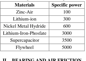
One of the major advantages of flywheels is the ability to handle high power levels as shown in table [1].
ISSN(E): 2277-128X, ISSN(P): 2277-6451, DOI: 10.23956/ijarcsse/V7I8/0123, pp. 90-95
The fast response time in flywheels makes them suitable to balance the grid frequency. As the energy contribution from more irregular renewable energy sources increases, this can be an important quality which will grow in importance.
Table 1. Specific Power comparison Materials Specific power
Zinc-Air 100
Lithium-ion 300 Nickel Metal Hydride 600 Lithium-Iron-Phosfate 3000
Supercapacitor 3500
Flywheel 5000
II. BEARING AND AIR FRICTION
• Friction is the biggest enemy to eat away, most of the energy stored in the flywheel. More over at very high speed of rotation, the friction is very high.
• Air friction at very high speed can increase to alarming levels. The rotating flywheel is preferably kept in a vacuum chamber or in a chamber at low air pressure.
III. REDUCING THE BEARING FRICTION
Bearing friction can be completely eliminated by using magnetic levitation technique. The shaft can be lifted away from the lower thrust bearing and also the guiding bearing. A passive magnetic levitation technique using super conductors is difficult to maintain due to need of liquid nitrogen to maintain the temperature. So electromagnets or permanent magnets are used.
IV. PARTIAL MAGNETIC LEVITATION TO REDUCE FRICTION
Magnetic bearings are very appealing for application to high rotating speeds and/or in severe environments such as low temperatures or vacuum due to the lack of mechanical contact between a rotor and a stator. The suspension of a rotor in a magnetic bearing is achieved by using interactions of an electromagnetic nature.
By the use of a permanent magnet to pull the shaft up, the force on the lower thrust bearing can be considerably reduced. A 10 Kg load on the thrust bearing can be reduced to only 1 Kg by using this technique. No electronic circuits are required but a little eddy currents are produced due to the permanent magnet used.
V. MAGNETIC BEARINGS
To overcome the drawback of high friction and short life in mechanical bearings, magnetic bearings came into use. A permanent or electro permanent magnetic bearing system is adaptable to modern high speed flywheels. Electro permanent magnetic bearings do not have any contact with the shaft, has no moving parts, experience little wear and require no lubrication. It consists of permanent magnets, which support the weight of the flywheel by repelling forces, and electromagnets are used to stabilize the flywheel, although it requires a complex guiding system. The best performing bearing is the high-temperature super-conducting (HTS) magnetic bearing, which can situate the flywheel automatically without need of electricity or positioning control system. This easily stabilizes the axle of the flywheel and reduces the friction.
ISSN(E): 2277-128X, ISSN(P): 2277-6451, DOI: 10.23956/ijarcsse/V7I8/0123, pp. 90-95
VI. FLYWHEEL BASICS
FEA model is described to achieve a better understanding of the mesh type, mesh size and boundary conditions applied to complete an effective FEA model. The fly wheel is modeled as a series of concentric rings through the software. The thickness within each ring varies linearly in the radial direction. A planar finite element model is used to represent a flywheel in which symmetry about the transverse direction and about the axis of rotation is used.
VII. STRUCTURAL ANALYSIS
Composite flywheels are being developed as an alternative to expensive and short-life chemical batteries. Flywheels promise orders of magnitude increases in performance and service life. It is the computation of deformation, internal forces and stresses. There are many methods for structural analysis. But here the structural analysis is done using finite element method (FEM).In FEA computer model of a material is stressed and analysed.There are two types of analysis. They are 2D and 3D analysis. Mesh analysis of flywheel can be done using free mesh and mapped mesh. With the help of solid works software the flywheel which was designed was analysed.The stress analysis was also done. The analysis has been tested on with mechanical bearings and same accounts also for magnetic bearings.
The energy stored in a flywheel can be measured from the moment of inertia which is dependent on the parameters of its rim. It is expressed as
MOMENT OF INERTIA = (Rim Density) (Rim Volume) (Rim Radius)2
ENERGY STORED = (1/2) (Moment of inertia) (Spin Speed)2
From the energy storage point of view, it is more advantageous to increase its angular velocity rather than its mass fig [1].
The main advantage of the flywheel material is the tensile strength which is maximum near its center and minimum at its periphery.
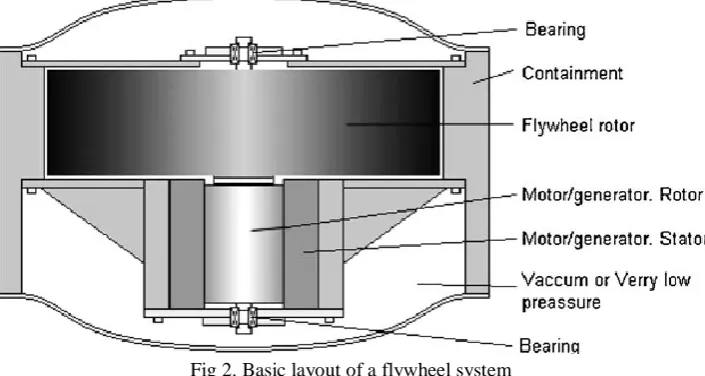
Fig 2. Basic layout of a flywheel system
In modern days, energy storage is required for stabilizing frequency of a grid against fluctuating demand and against fluctuating generation like that from wind, solar, tides and from many other renewable energy sources.
Storing the energy for a long time and making it available in a short period like for accelerating a car and also storing energy in a short period while braking the car are other requirements.
Making huge power of the order of a few gigawatts available within a short period to accelerate a car or an Aero-plane, for launching a satellite, or a missile are some other applications of flywheel storage system.
VIII. MATERIALS
Composite material having high tensile strength and low density for near centre and high density for periphery are preferred for the flywheel applications the flywheel applications [11-12]. Maximum energy density is provided by carbon reinforced composite materials.
IX. SECURITY ASPECTS
Flywheel spinning at a high speed could be a threat to personnel handling it. If the tensile force at any part of the flywheel exceeds its tensile strength, a fragment of the flywheel may get detached and fly out at very high speed. This can be a danger to life. It is not possible to make the entire flywheel uniformly at the crystal level.
ISSN(E): 2277-128X, ISSN(P): 2277-6451, DOI: 10.23956/ijarcsse/V7I8/0123, pp. 90-95
Fig 3.Gyro design and its components
X. MINIMIZATION OF GYROSCOPIC EFFECTS
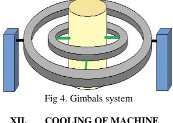
No problems due to gyroscopic effect are experienced when the flywheel is used on a stationary platform. However, problems are there when the flywheel is used on a moving platform like a ship, an aero-plane or a satellite. Some of these problems can be minimized by the use of two flywheels rotating in opposite directions. Flywheels need be mounted on a gimbal system to minimize other problems fig [2] .Gyroscope keeps the orientation of the flywheel fixed, regardless of the mounting platform’s motion, because the device mounted in the gimbals minimizes external torque. In the gyroscope flywheel the centre of gravity of the flywheel can be kept in fixed position. Design of a gyro and its components are as shown in fig [3].
XI. TYPE OF ELECTRICAL MACHINE
Permanent magnet synchronous machine or induction machines are used to input/output the electric power to a flywheel street. Due to its high power density, permanent magnet synchronous machine is more popular. A permanent magnet synchronous machine can be of Axial Field (AFPM) or a Radial Field (RFPM) type.
Fig 4. Gimbals system
XII. COOLING OF MACHINE
The AFPM fig [5a] can have two stators and one rotor (both sides of rotor are used) or two rotors and a single stator. Two stator and a single rotor type have better cooling due to more air-gap available. This feature is more important when less air is available for cooling.
As the electromagnetic machine used is operated under vacuum or under low air pressure, its cooling is a challenge. Heat produced in the stator can be better carried out using heat pipes.
XIII. HEAT PIPES
ISSN(E): 2277-128X, ISSN(P): 2277-6451, DOI: 10.23956/ijarcsse/V7I8/0123, pp. 90-95
XIV. POWER ELECTRONICS USED WITH FLYWHEEL
Two pole machines are generally used along with a flywheel. Frequency of input/output electric power is of the order of a few kilo hertz. If this power is used to be fed/removed to a grid for stabilizing the grid frequency, a power electronics circuit is required. The circuit should convert high frequency power from the flywheel system to D.C. by using a Rectifier/Inverter bridge. This DC is converted into grid frequency AC by another rectifier/inverter bridge.
Power can flow from flywheel to the grid if at the grid side; the voltage generated by the inverter leads the grid voltage. Reverse will happen for the power to flow from grid to the flywheel. On the flywheel side, power will flow into the flywheel when the inverter phase angle leads the shaft angle and vice versa. Phase angles of both side inverters should be so controlled that the power output from the flywheel is equal to the power fed to the grid plus losses. Or in other words, voltage of the D.C. supply should be kept constant.
XV. AXIAL AND RADIAL FIELD MACHINES
Fig 5. [a] shows an AFPM machine and [b] shows an RFPM machine arrangement
XVI. A FEW FLYWHEEL STORAGE SYSTEMS AVAILABLE
Small scale
Peak power buffers
Wind-Diesel system with flywheel storage
Flywheel with photovoltaic system
Harmonics
Flywheel in distribution network system
UPS System
Aerospace application
XVII. CONCLUSION
Flywheel storage system has its wide range of applications when used along with magnetic levitation. Material and semiconductor development are offering new possibilities and applications previously impossible for flywheels. Fast rotation of flywheel offer new possibilities of direct generation of high voltage. The motor/generator part has high possibilities of development.
REFERENCES
[1] Stodola A. Steam and gas turbines. New York: hMcGraw-Hill Book Company, Inc.; 1927.
[2] Bitterly JG. Flywheel technology: past, present, and 21st century projections. IEEE Aerospace Electron Syst Mag 1998;13:13–6.
[3] Storage Technology Report, ST6 Flywheel. "Next-gen Of Flywheel Energy Storage". Product Design & Development. Retrieved 2009-05-21.
[4] Vere, Henry. "A Primer of Flywheel Technology". Distributed Energy. Retrieved 2008-10-06. [5] Vattenkraften i Sverige Royal Swedish Academy of Engineering Sciences, IVA; 2002.
[6] Leijon M, Dahlgren M, Walfridsson L, Li Ming, Jaksts A. A recent development in the electrical insulation system of generators and transformers. IEEE Electrical Insulation Mag 2001;17(3):10–5.
ISSN(E): 2277-128X, ISSN(P): 2277-6451, DOI: 10.23956/ijarcsse/V7I8/0123, pp. 90-95
[8] Leijon M, Liu R. Energy technologies: electric power generators. vol. 3.: Landolt-Bo¨ rnstein; 2002 (Inbook 4) p. 151–164.
[9] Leijon M, Berggren B, Owman F, Karlsson T. High voltage power generators without transformers. J Hydropower Dams 1998;37(4):40.
[10] Johansson SG, Larsson B. Short circuit tests on a high voltage, cable wound hydropower generator. IEEE Trans Energy Convers 2004;19(1):28–33.
[11] 1.5kW Electromechanical battery system flywheel energy systems Inc. CETC-0100-01 Rev. 2.
![Fig 5. [a] shows an AFPM machine and [b] shows an RFPM machine arrangement](https://thumb-us.123doks.com/thumbv2/123dok_us/7813513.2086466/5.595.152.448.253.406/fig-shows-afpm-machine-shows-rfpm-machine-arrangement.webp)
