Comparative Study of Cable Stayed,
Suspension and Composite Bridge
Kumudbandhu Poddar
1, Dr. T. Rahman
2Assistant Professor, Dept. of Civil Engineering, C.I.T., Ranchi, India1
Associate Professor, Dept. of Civil Engineering, N.I.T.S., Silchar, India2
ABSTRACT: This study deals with the computational analysis of cable stayed bridge, suspension bridge and two types of composite type bridge. It also introduces a new composite bridge model where the long span deck is supported by stay cables and suspension cables at different portions along the whole longitudinal section of span. It includes comparative studies among these bridges. The Quincy Bayview Bridge located in Illinois, USA is taken as a reference for cable stayed bridge model. The geometries of these three bridges are same besides of some necessary structural components i.e. stay cables, suspension cables and hangers. For the comparison of these bridge models structural symmetries are considered. Static and dynamic effects of loads are taken into consideration for the analysis of these bridges. Analysis has been performed with the help of MIDAS CIVIL Software. Results indicate the changes come in performance and response of various members of bridge due to the change in hanging fashion of superstructure.
KEYWORDS: Cable Stayed Bridge, Suspension Bridge, Composite Bridge, Girder, Pylon, Nonlinear Static n Dynamic Analysis, Design guidelines.
I.INTRODUCTION
Long span bridges are widely used around the world. It might be chosen for the solution of huge and complicated traffic problems but it provides simultaneously a faster track of development to a country. Because of having lack of disturbance over the existing infrastructures and landscapes it has become a best selection for engineers, architects and government authorities also. Cable stayed and suspension bridge fulfils the requirements of long span bridge. Both types of bridge have non-linear structural behaviour. But they have their own structural limits, efficiencies, deficiencies and different ranges of limit of serviceability and durability for a particular geometry, loading and natural conditions. That’s why the analysis of these types of bridges is more complicated than conventional bridges. In these bridges, the stay cables or suspension cables are the main source of nonlinearity. So it’s a very tedious job for engineers to design and construct these bridges. The main issue of this paper is the mixing up of these two types of bridges in such a manner that it will provide better structural efficiencies and will become more economic and aesthetic.
II. MATHEMATICAL MODEL OF THE STUDIED BRIDGES II.I MODELING OF CABLE STAYED BRIDGE
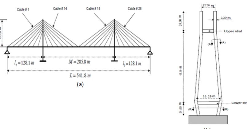
Fig 2.1: (a) front view of the cable stayed bridge model & (b) elevation of bridge pylon.
The bridge is composed of 56 nos. of staycables. The total length of the bridge L = 541.8 m with a main span length M = 285:6 m and two side spans l1 = l2 = 128.1 m as depicted in Fig. 2.1(a). The deck superstructure is supported by stay cables with a fan arrangement. The length of deck panel is 17.6 m whereas the middle deck panel length is 22.5 m. The middle deck panels are adjoined with pylons.
Fig 2.2: (a) cross section of bridge pylon & (b) cross section at mid span of cable stayed bridge model.
Fig 2.3: Sections of main girder, floor beam and stay cable.
The sections for main girder, floor beam, deck slab and pylon are taken as same that are used in reference bridge. Total depth of main girder is 3.16m and flange width is 1.5m. Width and depth of floor beam is 0.15m and 0.5m respectively. But the section for the stay cables has been assumed due to have the lack of data of the reference bridge. The stay cable of diameter 0.146m has taken.
Fig 2.4: Various fashions of arrangements of supports and bearings on bridge.
Now a days in most of the bridge engineers are using two types of fashion of placing bearing and supports into the bridge. These two type of arrangements of supports and bearings are shown in figure 2.4.In this comparative study the type 2 fashion has been taken for the bridge modelling because in this type we can avoid the issue of expansion joint by this we get a simpler form of bridge model.
II.II MODELLING OF SUSPENSION BRIDGE
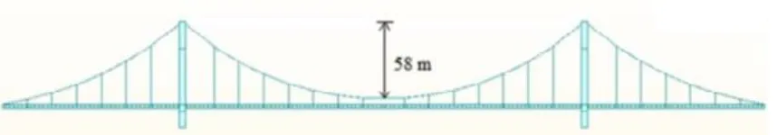
Fig 2.5: Front view of the suspension bridge model.
the suspension cable then transmit to the pylon. But in cable stay bridge the tension force directly transmit to the pylon after just flowing through the stay cable. That’s why we can notice that the suspension cable has the major role from the structural point of view. Here moving load also has been taken as the same of cable stayed bridge. The typical suspension bridge model is shown in fig 2.5.
Here girder, deck slab, pylon are taken same as like cable stayed bridge. Only two new structural sections had been added into this viz. suspension cable and hanger. The taken diameters of suspension cables and hangers are 0.47m and 0.155m.
II.III MODELLING OF COMPOSITE TYPE 1 BRIDGE
Fig 2.6: Front view of the composite type 1 bridge model.
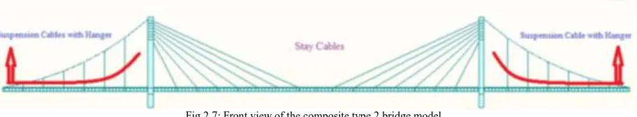
A new concept of bridge model for long span has been taken here. It’s a composite bridge model where stay cables as well as suspension cable are used. Here stay cables are used over the two cantilever spans and suspension cables with the hangers are used over middle span of the bridge. The middle span is hanging from suspension cables through the hangers and cantilever span is directly anchored to the pylon through the stay cables. So the transmission process of tension forces in left side and right side of every pylon are different. Here stay cables are playing two deferent roles i.e. it is acting as stiffener for the cantilever span and simultaneously anchoring the middle span. So it’s a self-anchored structure. Besides of stay cable, suspension cable and hangers all the structural components or geometry are kept same as like the cable stay bridge model or suspension bridge model. The deck panel length and section or diameter of stay cables are same as of cable stay bridge and the sections of suspension bridge and hangers are same as of suspension bridge. These structural components had been kept remain for comparison studies purpose. A typical composite type 1 bridge model is shown in fig 2.6.
II.IV MODELING OF COMPOSITE TYPE 2 BRIDGE
Fig 2.7: Front view of the composite type 2 bridge model.
II.V LOADING FOR ANALYSIS
Here the static load for the bridge is only the self weight of every structural member. The Quincy Bayview Bridge has taken as the reference bridge for this thesis. This bridge is located in Illinois, USA across the misicipy river. Hence the AASHTO LRFD code was referred for the moving load analysis for this cable stayed bridge model. The moving load analysis for this bridge included two lanes both way traffic flows . HL- 93TDM was assigned as the vehicle class for the both lanes .
III.ANALYZED RESULTS OF BRIDGE MODELS
Analyzed results of cable stayed, suspension, composite type 1 and type 2 bridges are given on the basis of displacements, axial force and bending moments over cantilever span and middle span of these bridges.
III.I DISPLACEMENTS IN STEEL GIRDER IN VERTICAL DIRECTION
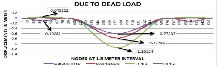
Here the displacements in vertical direction at various points of steel girder for every bridge model are given. Points are taken at a particular distance of 1.5 m. All the displacements are in meter.
Fig 3.1:Displacements in steel girder due to dead load.
Fig 3.2:Displacements in steel girder due to moving load.
As per IS code the maximum displacement limit for the main girder span of the bridge due to dead load is = Span length / 325 that is for this examined bridge model is 0.8772 m and for the cantilever span of the bridge due to dead load is = 2 X (span length / 325) that is for this examined bridge model is 0.7883 m. In middle span and cantilever span the maximum displacement for cable stayed, suspension, composite type 1 and type 2 bridge model are 0.05499m, -0.06139 m,-0.07263 m, -0.05081 m,-0.01192 m, -0.02268 m, -0.01192 m and - 0.02257 m respectively. Hence all the maximum displacements are under maximum permission limit.
III.IIDISPLACEMENTS OF CONCRETE PYLON IN LONGITUDINAL DIRECTION OF GIRDER OR IN X-DIRECTION
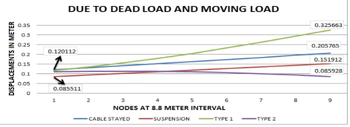
The displacements at various points of concrete pylon in longitudinal direction of girder for every types of bridge are given in graphical form in figure 3.3. Points are taken at a particular distance of 8.8 m. Points are taken from base to top of pylon. All the displacements are in meter unit.
Fig 3.3: Displacements in concrete pylon due to dead load and moving load.
III.III AXIAL FORCE ON STAY CABLES, SUSPENSION CABLES AND HANGERS OVER CANTILEVER SPAN
III.III.I AXIAL FORCE ON STAY CABLES OF CABLE STAYED AND COMPOSITE TYPE 1 BRIDGE
Cable stayed and composite type 1 bridge has same type geometry i.e. same nos. and size of stay cables over the cantilever span. Axial forces or tensile forces in stay cables are compared in between these two type of bridges. Graphs of these tensile forces for dead load and moving load are given fig. 3.4.
Fig 3.4: Tensile forces in stay cables due to dead load and moving load.
Due to dead load and moving load maximum tensile force which is 6128.08 kn ,has come in stay cable no. 1 for composite type 1 bridge. Whereas in cable stayed bridge maximum tensile force which is 4256.27 kn, has come in stay cable no. 3. In stay cable no. 6 & 7 tensile force is same for both type of bridge. Over all composite type 1 bridge has greater tensile forces in stay cables.
III.III.II AXIAL FORCE ON SUSPENSION CABLES OF SUSPENSION AND COMPOSITE TYPE 2 BRIDGE
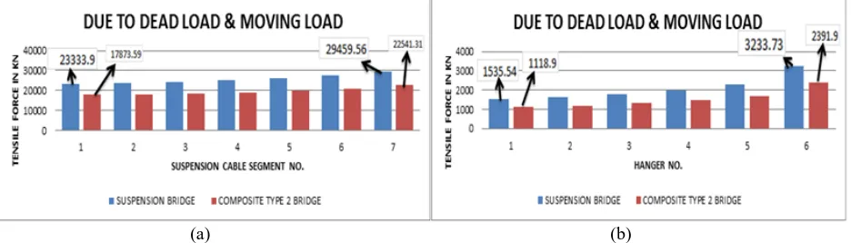
Axial forces or tensile forces in suspension cables are compared in between these two type of bridges. Graphs for these respective tensile forces for dead load and moving load are shown in fig. 3.5(a).
(a) (b)
Fig 3.5: Tensile forces in (a) suspension cables & (b) hangers due to dead load and moving load.
III.III.III AXIAL FORCE ON HANGERS OF SUSPENSION AND COMPOSITE TYPE 2 BRIDGE
Axial forces or tensile forces in hangers are compared in between suspension and composite type 2 bridge. Graphs for these respective tensile forces for dead load and moving load are shown in fig. 3.5(b).Due to dead load and moving load maximum tensile force which is 3233.73 kn, has come in hanger no.6 which is near by the pylon for suspension bridge and also for composite type 2 bridge the maximum tensile force which is 2391.9 kn, has come also in hanger no. 6. Over all suspension bridge has greater tensile forces in hangers.
III.IV AXIAL FORCE ON STAY CABLES, SUSPENSION CABLES AND HANGERS OVER MIDDLE SPAN III.IV.I AXIAL FORCE ON STAY CABLES OF CABLE STAYED AND COMPOSITE TYPE 2 BRIDGE
In middle span cable stayed and composite type 2 bridge has same type geometry i.e same number and size of stay cables are present. Axial forces or tensile forces in stay cables are compared in between these two types of bridges. Graphs for these respective tensile forces for dead load and moving load are shown in fig. 3.6.
Fig 3.6: Tensile forces in stay cables due to dead load and moving load.
Due to dead load and moving load in cable stayed bridge maximum tensile forces 4992.9 kn and 5010.95 kn has come in stay cable no. 5 & 10 respectively. And in composite type 2 bridge maximum tensile forces 4950.2 kn and 5000.35 kn has come in stay cable no. 5 & 10 respectively.Stay cables of cable stayed bridge has more tensile force than that of composite type 2 bridge besides stay cable no. 6, 7, 8 and 9 which are existed in the middle portion of middle span. So it can be said that stay cables of composite type 2 bridge carry less amount of tensile force.
III.IV.II AXIAL FORCE ON SUSPENSION CABLES OF SUSPENSION AND COMPOSITE TYPE 1 BRIDGE
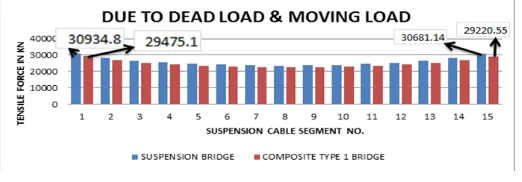
Axial forces or tensile forces in suspension cables are compared in suspension and composite type 1 bridge. Graphs for these respective tensile forces for dead load and moving load are shown in fig. 3.7.
Fig 3.7: Tensile forces in suspension cables to dead load and moving load.
suspension cable segment no. 1 & 15 which are near by the pylons of suspension bridge and for composite type 1 bridge the maximum tensile force which are 29475.1 kn and 29220.55 kn, have come also in suspension cable segment no. 1 & 15. Over all suspension bridge has greater tensile forces in suspension cables.
III.IV.III AXIAL FORCE ON HANGERS OF SUSPENSION AND COMPOSITE TYPE 1 BRIDGE
Fig 3.8: Tensile forces in hangers to dead load and moving load.
Axial forces or tensile forces in hangers are compared in between these two type of bridges. Graphs for these respective tensile forces for dead load and moving load are shown in fig. 3.8. Due to dead load and moving load maximum tensile forces which are 4140 kn and 2414 kn, have come in suspension cable segment no. 1 & 15 which are near by the pylons for suspension bridge and for composite type 1 bridge the maximum tensile forces which are 3926 kn and 2284.7 kn, have come also in suspension cable segment no. 1 & 15. Over all suspension bridge has greater tensile forces in hangers.
III.V BENDING MOMENT IN STEEL GIRDER
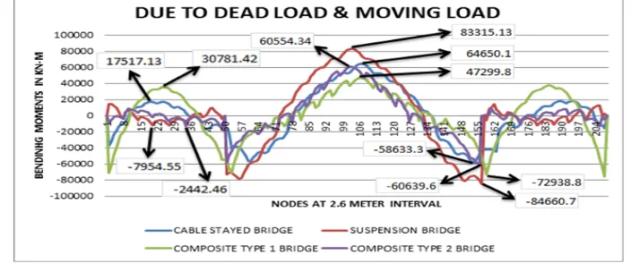
Here the bending moments at various points of steel girder for every type of bridge model are shown. Points are taken at a particular distance of 2.6 m. Here bending moments are shown in graphical form due to dead load and moving loads (see fig. 3.9).
Fig 3.9: Bending moments in steel girder due to dead load and moving load.
maximum positive bending moment that is 30781.42 kn-m. But in middle span composite type 1 has minimum positive bending moment that is 47299.8 kn-m. So over all composite type 2 bridge has lesser bending moments throughout the length of steel girder due to dead load.
III.VI BENDING MOMENT IN CONCRETE PYLON
Here the bending moments at various points of concrete pylon in longitudinal direction of girder direction for every types of bridge model are shown. Points are taken at a particular distance of 2.46 m. Points are taken from base to top of pylon. Bending moments are shownin graphical form in figure 3.10.
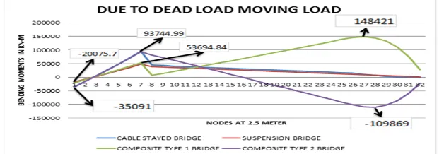
Fig 3.10: Bending moments in concrete pylon due to dead load and moving load.
At the base point of pylon every bridge model has negative bending moment. Values of these negative bending moments for cable stayed, suspension, composite type 1 and type 2 are -35860.6 kn-m, -17895 kn-m, -20075.7 kn-m and -35091 kn-m respectively. After that it reduces for every type of bridge model and got relative maximum positive bending moment, at the level where the girder is resting, are 95788.59 kn-m, 47881.8 kn-m, 53694.84 kn-m and 93744.99 kn-m. After just above the girder level bending moment is reducing for every type of bridge model. In cable stayed and suspension bridge this positive bending moment is reducing continuously to a lower value of positive bending moment. But in composite type 1 bridge after getting lower positive bending moment 6956.99 kn-m at node no. 8 the bending moment increase again very rapidly and gets a maximum positive bending moment 148421 kn-m at node no 27. After that it is decreased to28073.91 kn-m at the top point of pylon. In composite type 2 bridge after getting maximum value at node no. 7 the bending moment reduces very rapidly and gets the maximum negative bending moment -109869kn-m at node no. 28. After that it is increased to -21958.6kn-m at the top of pylon.
IV. CONCLUSIONS
The specific conclusions that can be drawn after comparing and judging displacements, tensile forces and bending moment’s value of every bridge models w.r.t. their structural components are numerated as follows:
1. Maximum displacements in steel girder for cable stayed and suspension bridge are under the maximum limit
of displacement. Composite type 1bridge has maximum displacement greater than the maximum limit of displacement. But the composite type 2 bridge model having displacements in steel girder are noticeably lesser than that of cable stayed and suspension bridge. So composite type 2 bridge has better structural stability than others.
2. In pylon the maximum and minimum displacement occurs at base point for cable stayed and suspension bridge
respectively.But the maximum and minimum displacement at top point is occurring in composite type 1 and type 2 bridges respectively. Among all these four types of bridge composite type 2 bridge has comparatively less displacement at base and top point or throughout the pylon length.
model is lesser than that of suspension cable.
4. In middle span, tensile force in stay cables of cable stayed bridge is more than that of composite type 2 bridge
besides of those stay cables which are existed at the middle portion of middle span. Whereas tensile force in suspension cables and hangers of composite type 1 bridge is less than that of suspension bridge throughout the middle span length.
5. Composite type 1 bridge has maximum positive bending moment at the center of cantilever span than other bridges. Whereas suspension bridge has maximum negative bending moment in that position.
6. In middle span, suspension bridge has maximum bending moment than other bridges. While composite type 1
bridge has minimum bending moment in middle span.
7. In pylon, below the girder level cable stayed and composite type 2 bridge has maximum positive bending
moment than other two bridges. But above the girder level composite type 1 bridge has maximum positive bending moment whereas composite type 2 bridge has maximum negative bending moment.
REFERENCES
[1] A. Baldomir, S. Henandez, F. Nieto, and A Jurado.Cable Optimization of a Long Span Cable-Stayed Bridge in La Coura (Spain). Journal of Advances in Engineering Software, 41:931–938, 2010.
[2] D. Jajnic, M. Pircher, and H Pircher. Optimization of Cable Tensioning in Cable- Stayed Bridges. Journal of Bridge Engineering, 8:131–137, 2003.
[3] H. Bernard, Isler Walmer, and Moia Pierre, editors. Cable Stayed Bridges. Presses PolytechniquesRomandes, Lausanne, Switserland, 1988.ISBN 0-7277-1321-3.
[4] John. Wilson and Wayne Gravelle. Modelling of A Cable-Stayed Bridge For Dynamic Analysis. Journal of Erthquake Engineering and Structural Dynamics, 20:707–771, 1991.
[5] K. Tori, K. Ikeda, and T Nagasaki. A Non-iterative Optimum Design Method for Cable-Stayed Bridges. In Proceedings of Japan Society of Civil Engineers, pages 115–123, 1968.
[6] LMC. Simoes and JHJO Negrao.Sizing and Geometry Optimization of Cable-stayed Bridges. Journal of Computer and Structure, 52:309–321, 1994.
[7] M.M. Hassan, A. A. El Damatty, and Nassef.Determination of Optimum Post- Tensioning Cable Forces for Cable-stayed Bridges.Journal of Engineering Structures, in press, 2012.
[8] PH. Wang, TC. Tseng, and CG Yang. Initial Shape of Cable Stayed Bridges. Journal of Computational Structure, (46):1095–1106, 1993. [9] Tao. Zhang and ZhiMin Wu.Dead Load Analysis of Cable-Stayed Bridge.In International Conference on Intelligent Building and Management (CSIT’11), pages 270–274, 2011.
[10] T.Y. Lee, Y.H. Kim, and S.W. Kang. Optimization of tensioning strategy for asymmetric cable-stayed bridge and its effect on construction process. Structural and Multidisciplinary Optimization, 35(6):623–629, 2008.