IPv6 Security Assessment and
Benchmarking
Abstract Test Suite
Version 1.0
2013-01-22
Copyright (C) 2012, 2013
EANTC European Advanced Networking Test Center Aktiengesellschaft This document is copyrighted by EANTC AG. It may not, in whole or in part, be reproduced, transmitted by any means or stored in any web site or electronic retrieval system without the prior written permission of EANTC AG. EANTC AG grants the receiving party of this test plan a non-transferrable right to use this document for internal purposes with regards to projects with EANTC.
All copies must retain and reproduce this copyright notice and all other copyright notices contained within the original material.
Salzufer 14 D–10587 Berlin Germany
Tel. +49. (0)30. 318 05 95–0 Fax +49. (0)30. 318 05 95–10
3
Introduction ... 5
Version History ... 6
Authors and Contributors ... 6
References ... 6
IPv6 Firewall Protocol Tests ... 9
Test Setup ... 10
ICMPv6 Filtering ... 11
IPv6 Routing Headers ... 12
IPv6 Header Chain Inspection ... 13
Filtering Packets According To IPv6 Headers ... 14
Overlapping IPv6 Fragments ... 15
Tiny IPv6 Fragments ... 16
Hop-by-Hop/Destination Options Policy... 17
Excessive Hop-by-Hop Options ... 18
PadN Covert Channel ... 19
Address Scopes... 20
Filtering IPv6 Tunneling... 21
IPv6 Firewall Load Test ... 22
Test Setup ... 23
Layer 3 Throughput ... 25
TCP Concurrent Connections ... 26
TCP Connection Setup Rate... 27
Application Layer Throughput... 28
Latency... 29
Layer 3 Throughput with IPv6 Extension Header Chain ... 30
IPv6 Fragmentation ... 32
Malicious IPv6 Fragmentation... 33
Reset Recovery ... 34
System Overload Recovery ... 35
IPv6 IDS Tests... 36
Test Setup ... 36
Spoofed Neighbor Discovery Messages ... 38
Duplicate Address Detection DoS... 39
Spoofed Redirect Message... 40
Spoofed Zero-Lifetime Router Advertisement Messages ... 41
Router Advertisements Flooding ... 42
5 This document details an abstract test suite for various aspects of IPv6 security: firewall protocol tests, firewall load test and IDS functionality tests. This abstract test suite is a product of the “IPv6 Intrusion Detection System” project, commissioned by the German Federal Ministry of Education and Research (Bundesministerium für Bildung und Forschung).
For more information on the project please refer to the project’s homepage at the following address: http://www.ipv6-ids.de
The following table shows the version history and change descriptions:
TABLE 1. Version History Overview
Version Date Author Changes
1.0 Jan 23, 2013 EANTC – Initial abstract test suite version.
Authors and Contributors
Universität Potsdam, Institut für Informatik, August-Bebel-Strasse 89, 14482 Potsdam
Prof. Dr. Bettina Schnor Klemens Kittan
Simon Kiertscher Oliver Eggert
Beuth-Hochschule Berlin,Luxemburger Straße 10, 13353 Berlin Prof. Dipl.-Inform. Thomas Scheffler,
Sven Schindler
EANTC AG, Salzufer 14, 10587 Berlin Herbert Almus, Supervisory Board Chairman Eldad Zack, Test Engineer
References
“Security Considerations for IP Fragment Filtering“, RFC 1858, October 1995
“Internet Protocol, Version 6 (IPv6)“, RFC 2460, December 1998 “Benchmarking Methodology for Network Interconnect Devices“, RFC 2544, March 1999
“Benchmarking Terminology for Firewall Performance“, RFC 2647, August 1999
“Benchmarking Methodology for Firewall Performance“, RFC 3511, April 2003
“IPv6 Neighbor Discovery (ND) Trust Models and Threats“, RFC 3756, May 2004
“Mobility Support in IPv6“, RFC 3775, June 2004
“Internet Control Message Protocol (ICMPv6) for the Internet Protocol Version 6 (IPv6) Specification“, RFC 4443, March 2006
7 “IPv6 Transition/Coexistence Security Considerations“, RFC 4942,
September 2007
“Deprecation of Type 0 Routing Headers in IPv6“, RFC 5095, December 2007
“IPv6 Benchmarking Methodology for Network Interconnect Devices“, RFC 5180, May 2008
“Handling of Overlapping IPv6 Fragments“, RFC 5722, December 2009 “Special Use IPv4 Addresses“, RFC 5735, January 2010
“Security and Interoperability Implications of Oversized IPv6 Header Chains“, Work in Progress, draft-gont-6man-oversized-header-chain-02, Expires December 15, 2012
“Security Implications of IPv6 on IPv4 Networks“, Work in Progress, draft-ietf-opsec-ipv6-implications-on-ipv4-nets-02, Expires July 1, 2013
“Tiny Fragments in IPv6“, Work in Progress, draft-manral-6man-tiny-frag-ments-issues-00, Expires August 5th, 2012
“RA-Guard Implementation Advice“, Work in Progress, draft-ietf-v6ops-ra-guard-implementation-07, Expires May 18, 2013
“The Rose IP Fragmentation Attack“, http://www.checkpoint.com/defense/ advisories/public/2004/cpai-2004-16.html, Retrieved March 6th, 2012 “Internet Protocol Version 6 (IPv6) Parameters“, http://www.iana.org/ assignments/ipv6-parameters/ipv6-parameters.xml, Retrieved March 19th, 2012
“Internet Control Message Protocol version 6 (ICMPv6) Parameters“, http:// www.iana.org/assignments/icmpv6-parameters, Retrieved April 20th, 2012
“IANA IPv4 Address Space Registry“, http://www.iana.org/assignments/ ipv4-address-space/ipv4-address-space.xml, Retrieved June 15th, 2012 “IANA IPv6 Special Purpose Address Registry“, http://www.iana.org/ assignments/iana-ipv6-special-registry/iana-ipv6-special-registry.xml, Retrieved May 14th, 2012
“ICMPv6 Router Announcement flooding denial of service affecting multiple systems“, http://www.mh-sec.de/downloads/mh-RA_flooding_CVE-2010-multiple.txt, Retrieved May 4th, 2012
CTP Coexistence Traffic Pattern DoS Denial of Service
DSTOPT Destination Options (IPv6 Header) DUT Device Under Test
HBH Hop-by-Hop (IPv6 Header)
ICMPv6 Internet Control Message Protocol for IPv6 IPS Intrusion Prevention System
IPv4 Internet Protocol, Version 4 IPv6 Internet Protocol, Version 6 MLD Multicast Listener Discovery MRD Multicast Router Discovery ND Neighbor Discovery
NUD Neighbor Unreachability Detection Pad1 Padding Options, Length 1 PadN Padding Options, Variable Length RFC Request For Comment
RH Routing Header
RH0 Routing Header Type 0 (Source Routing) RH2 Routing Header Type 2 (IPv6 Mobility)
9
Tests
This chapter is dedicated to testing the behavior of the reference firewall with respect to IPv6. The focus in this chapter will be the correct behavior, alerts generated by the firewall as well as the configuration of IPv6 security policy.
Test Setup
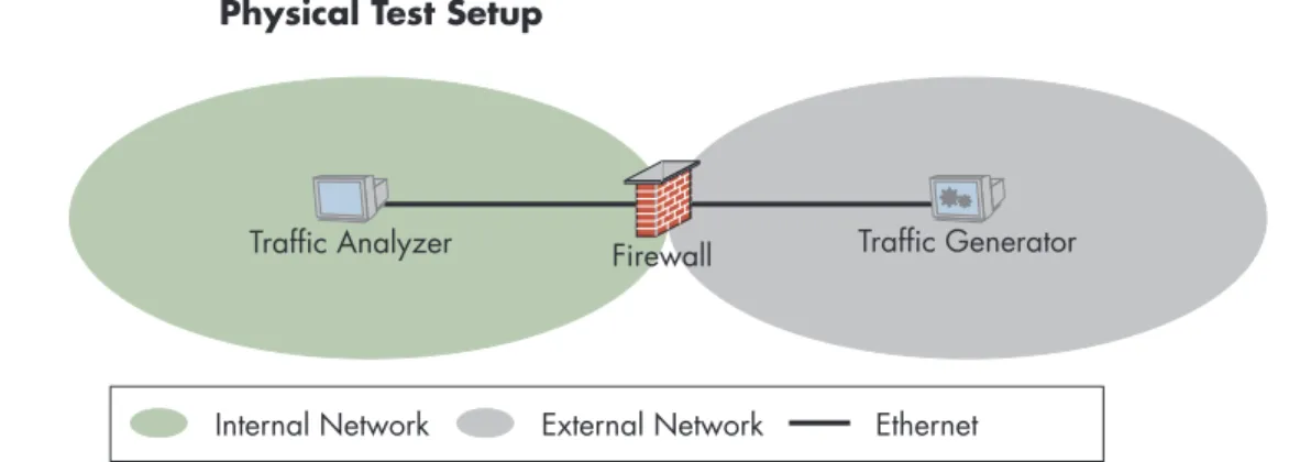
In this chapter we will used one test setup to run all the protocol tests. The traffic generator will be connected to the external facing interface and a traffic analyzer will be connected to the internal network interface.
FIGURE 1. Physical Test Setup
Internal Network External Network Ethernet Firewall Traffic Generator Traffic Analyzer
11
1.1 ICMPv6 Filtering
PURPOSE Verify the correct filtering of various ICMPv6 messages by the firewall. DESCRIPTION The IETF recommendation for filtering ICMPv6 messages in firewall is
speci-fied in the informational RFC 4890. This test will verify that the firewall can be configured with the corresponding policy and filters the ICMPv6 messages accordingly.
TEST PARAMETERS • Firewall policies according to RFC 4890, section 4.3, “Recommenda-tions for ICMPv6 Transit Traffic“.
TEST PROCEDURE & EXPECTED RESULTS
• Test shall be performed for each the firewall policies. • Apply the tested policy.
• Generate all possible ICMPv6 messages (and sub-codes where appli-cable).
• All allowed ICMPv6 types are expected to traverse the firewall. If the fire-wall performs stateful inspection on ICMPv6, error reports are expected to be filtered with a corresponding notification from the firewall.
REFERENCES “Recommendations for Filtering ICMPv6 Messages in Firewalls“, RFC 4890, May 2007
“Internet Control Message Protocol version 6 (ICMPv6) Parameters“, http:// www.iana.org/assignments/icmpv6-parameters, Retrieved April 20th, 2012
1.2 IPv6 Routing Headers
PURPOSE Verify that the firewall processes the deprecated Type 0 Routing Header (RH0) according to IETF standards. Verify that the firewall processes addi-tional types of routing headers according to IETF standards.
DESCRIPTION The Type 0 Routing Header (RH0) was deprecated by RFC 5095 due to security consideration and specifies the mandatory behavior of IPv6 node receiving packets with the RH0 header, which is to treat the RH0 header as an unknown routing header.
Since the usage of other routing headers, such as the Type 2 Routing Header used for IPv6 Mobility, might be desired, the firewall should allow filtering according to the routing header type. RFC 5095 mandates that the default configuration must permit forwarding traffic with a routing header other than the type 0 header. This test will verify that the firewall does not forward RH0 by default, and does forward other header types. It must be noted if addi-tional policy configuration is required for the firewall to do so.
Note that RFC 3775 sets requirements to the “Segments Left” field for Routing Header 2.
TEST PARAMETERS • List of routing header to be tested shall comprise of, at least: – The deprecated Type 0 Routing Header – RH0
– Mobility Routing Header – RH2
– An additional unallocated Routing Header
• The following list describes the minimal set of “Segments Left” field values to be tested:
– “0” – “1”
– A value in the range “1” to “255”. TEST PROCEDURE &
EXPECTED RESULTS
• Verify that the currently applied firewall policy contain no rules appli-cable to IPv6 routing headers.
• Test shall be performed for each of the routing headers and possible “Segments Left” values per test parameters.
• Generate traffic with the selected routing header and “Segments Left” value.
• All of the generated Traffic shall be either dropped or forwarded, conforming to IETF standards.
REFERENCES “Internet Protocol, Version 6 (IPv6)“, RFC 2460, December 1998 “Mobility Support in IPv6“, RFC 3775, June 2004
“Internet Control Message Protocol (ICMPv6) for the Internet Protocol Version 6 (IPv6) Specification“, RFC 4443, March 2006
“Deprecation of Type 0 Routing Headers in IPv6“, RFC 5095, December 2007
“Internet Protocol Version 6 (IPv6) Parameters“, http://www.iana.org/ assignments/ipv6-parameters/ipv6-parameters.xml, Retrieved March 19th, 2012
13
1.3 IPv6 Header Chain Inspection
PURPOSE Verify that the firewall inspects the IPv6 header chain correctly according to the IPv6 base specification and blocks invalid header chains.
DESCRIPTION The base IPv6 specification specifies a valid IPv6 header chain:
• Destination Options header should occur at most twice (once before a Routing header and once before the upper-layer header).
• All other extension headers should occur at most once.
• The Hop-by-Hop Options header is restricted to appear only immediately after the base IPv6 header.
TEST PARAMETERS • The minimal List of IPv6 header chains to be tested shall comprise of: – Valid header chain including a “Destination Options” header. – Valid header chain including a “Hop-by-Hop Option” header. – Invalid header chain, which includes more than 2 occurrences of the “Destination Options” header.
– Invalid header chain, which includes a “Hop-by-Hop Options” header after a header other than the IPv6 base header
– For all other standardized headers: invalid header chains, which includes double occurrence of each of the standardized headers (excluding “Hop-by-Hop Options” and “Destination Options” types). TEST PROCEDURE &
EXPECTED RESULTS
• Verify that the currently applied firewall policy contain no rules appli-cable to IPv6 extension headers.
• Generate traffic with the selected chain.
• Traffic with valid header chains shall undergo no traffic loss. Conversely, traffic with invalid header chains shall not be forwarded.
1.4 Filtering Packets According To IPv6
Headers
PURPOSE Verify that the firewall inspects the IPv6 header chain and filters packets correctly according to the configured policy.
DESCRIPTION The IPv6 Extension Headers may introduce functionality that is risk prone or undesired according to the security policy of the organization. An IPv6 fire-wall must be able to inspect the IPv6 header chain and apply the policy as configured.
RFC 4942 section 2.1.9 discusses processing header chains in “middle-boxes” such as Firewall.
TEST PARAMETERS • A list of at least 2 valid extension header chains. TEST PROCEDURE &
EXPECTED RESULTS
• Apply a policy to allow all of the extension header chains defined in the test parameters and generate traffic. No traffic loss is expected.
• Apply a policy to deny all of the extension header chains defined in the test parameters and generate traffic. 100% traffic loss is expected. REFERENCES “IPv6 Transition/Coexistence Security Considerations”, RFC 4942
15
1.5 Overlapping IPv6 Fragments
PURPOSE Verify that the firewall, upon receipt of overlapping IPv6 fragmented packets, silently discards the entire datagram.
DESCRIPTION The security consideration for IPv4 fragmented traffic is well-known and documented in the informational RFC 1858. This issue seems to be more complex in IPv6, since the fragmentable part can contain more headers before the upper layer header. Furthermore, using overlapping fragments may allow an attack to rewrite the upper layer header, especially port numbers and flags. RFC 5722 describes the attack vector in section 3 and the expected node behavior in section 4 – a datagram with overlapping fragments must be silently dropped.
TEST PARAMETERS • The minimal list of overlapping IPv6 fragments patterns shall contain: – Traffic with overlapping fragments which rewrite a part of the upper layer protocol header.
– Traffic with overlapping fragments which does not rewrite the upper layer protocol header, but rewrite a part of the payload.
• The patterns shall be not contain gaps, i.e., reassembly shall be always possible.
TEST PROCEDURE & EXPECTED RESULTS
• Generate traffic with non-overlapping fragments. No traffic loss is expected.
• Generate traffic with each of the IPv6 fragments patterns. 100% traffic loss is expected.
REFERENCES “Security Considerations for IP Fragment Filtering“, RFC 1858, October 1995
1.6 Tiny IPv6 Fragments
PURPOSE Verify that the firewall processes tiny IPv6 fragments correctly and drops the datagram after a time out if not all fragments were received.
DESCRIPTION Tiny fragments are fragments which do not contain the upper layer header in the first fragment. One can also apply an oversized header chain in order to force the upper layer header to the second fragment.
Using such fragments one can attack a node in a similar way to the “IP Rose Attack”.
TEST PARAMETERS • No specific parameters. TEST PROCEDURE &
EXPECTED RESULTS
• Generate valid traffic with tiny fragments. No traffic loss is expected. • Generate only the first fragment of a tiny fragment stream. Wait for the
timeout value set in the firewall policy, but not exceeding the require-ments set by RFC 2460. Generate the rest of the fragrequire-ments. 100% traffic loss is expected.
REFERENCES “Internet Protocol, Version 6 (IPv6)“, RFC 2460, December 1998 “Tiny Fragments in IPv6”, Work in Progress, draft-manral-6man-tiny-frag-ments-issues-00, Expires August 5th, 2012
“Security and Interoperability Implications of Oversized IPv6 Header Chains“, Work in Progress, draft-gont-6man-oversized-header-chain-02, Expires December 15, 2012
“The Rose IP Fragmentation Attack”, http://www.checkpoint.com/defense/ advisories/public/2004/cpai-2004-16.html, Retrieved March 6th, 2012
17
1.7 Hop-by-Hop/Destination Options Policy
PURPOSE Verify that the firewall processes Hop-by-hop/Destination options and filters packets that contain such options according to the configured policy. DESCRIPTION While some IPv6 options, such as IP Mobility and tunnel encapsulation, may
be allowed, other may be need to be filtered, as required by the security policy. As the options are structured in a TLV form, it is also possible to define a policy for unknown options, as discussed in RFC 4942 section 2.1.9.3. This test will verify that a policy can be configured on the firewall to forward or block packets carrying specific options either in the Hop-by-Hop header or in the Destination Options header.
TEST PARAMETERS • The minimal list of Hop-by-Hop/Destination Options types shall contain: – Jumbo Payload
– Tunnel Encapsulation Limit – Router Alert
– Home Address
– Unassigned option with the “act” field set to 00.
• The minimal list of Hop-by-Hop/Destination Options profiles shall contain:
– For each member of the types list above, a profile containing only the option (and additional padding if needed).
– At least 4 of the possible option types permutations. Each option type shall appear in at least one profile and once per profile.
TEST PROCEDURE & EXPECTED RESULTS
• Configure firewall policy to allow traffic matching the profiles in the test parameters. Generate traffic according to the profile. No traffic loss is expected.
• For each of the profiles, modify firewall policy to drop matching traffic. Generate traffic according to the profile. 100% traffic loss is expected. REFERENCES “IPv6 Transition/Coexistence Security Considerations“, RFC 4942,
September 2007
“Internet Protocol Version 6 (IPv6) Parameters“, http://www.iana.org/ assignments/ipv6-parameters/ipv6-parameters.xml, Retrieved March 19th, 2012
1.8 Excessive Hop-by-Hop Options
PURPOSE Verify that the firewall detects IPv6 packets with excessive number of hop-by-hop options and applies the security policy.
DESCRIPTION With the possible exception of the padding options (Pad1, PadN), options should not appear more than once in any given IPv6 packet, as discussed in RFC 4942 section 2.1.9.4. This test verifies that the firewall detects and can filter such packets. It must be noted if additional policy configuration is required for the firewall to do so.
TEST PARAMETERS • The minimal list of Hop-by-Hop/Destination Options types shall contain: – Jumbo Payload
– Tunnel Encapsulation Limit – Router Alert
– Home Address
– Unassigned option with the “act” field set to 00.
• The minimal list of Hop-by-Hop/Destination Options profiles shall contain:
– For each member of the types list above, a profile containing only the option repeated twice (and additional padding if needed).
– At least 4 of the possible option types permutations. Each option type shall appear twice in at least one profile. Only one option shall appear twice in a single profile.
TEST PROCEDURE & EXPECTED RESULTS
• Verify the currently applied policy contain no rules applying to Hop-by-Hop/Destination Options.
• Generate traffic according to each of the defined profile in a Hop-by-Hop options header. 100% traffic loss is expected.
• Generate traffic according to each of the defined profile in a Destination Options header. 100% traffic loss is expected.
REFERENCES “IPv6 Transition/Coexistence Security Considerations“, RFC 4942, September 2007
19
1.9 PadN Covert Channel
PURPOSE Verify that the firewall detects and can block packets with non-zero padding in the IPv6 header.
DESCRIPTION The PadN option is used to insert two or more octets of padding into the Option area of a header, in order to align the headers to multiples of 8 bytes. This is required since the length of the Hop-by-Hop header and the Destination Options header is specified is multiples of 8 bytes. The PadN header can also be used as a covert channel using a the option data field. RFC 4942 discusses this issue in section 2.1.9.5 and recommends that the firewall should verify that the PadN option payload contains only zeroes. This test will be performed with the Hop-by-Hop header, which should be examined by any IPv6 node forwarding the packet, as well as the Destina-tion OpDestina-tions header.
TEST PARAMETERS • One valid set of Hop-by-Hop/Destination options, excluding padding. • The minimal list of PadN payload values shall contain:
– A non-zero value TEST PROCEDURE &
EXPECTED RESULTS
• Test shall be performed at least once using a Hop-by-Hop Options header and once using a Destination Options header. The number of test runs for each enclosing header type shall match.
• Generate traffic using the valid set of options and PadN with zero payload. No traffic loss is expected.
• Generate traffic using the valid set of options and PadN with payload values according to the test parameters. 100% traffic loss is expected. REFERENCES “Internet Protocol, Version 6 (IPv6)“, RFC 2460, December 1998
“IPv6 Transition/Coexistence Security Considerations“, RFC 4942, September 2007
1.10 Address Scopes
PURPOSE Verify that the firewall does not route IPv6 packets matching an inappro-priate scope.
DESCRIPTION In this test, we will verify that the firewall accounts for packets containing addresses with inappropriate scope. We will test two scopes:
• Multicast addresses
Addresses from ff00::/16 are used for multicast and are not to be used as source addresses.
• Link-local addresses
Addresses from fe80::/10 are used for link-local scoped addresses. This scope is sometimes specified as fe80::/64. IPv6 nodes should not forward any packets with source or destination address from the link-local scope.
TEST PARAMETERS • Valid destination address prefix (may also be a single host). • One valid unicast-scoped source address.
• The minimal list of tested source addresses shall contain: – An address from the multicast scope.
– An address from the “Link-Local” scope. TEST PROCEDURE &
EXPECTED RESULTS
• Configure firewall policy to allow any address to communicate with the valid destination address prefix.
• Generate traffic with the valid unicast-scoped source address to the valid destination address prefix. No traffic loss is expected.
• Generate traffic for each of the source addresses in the test parameters to the valid destination address prefix. 100% traffic loss is expected. REFERENCES “Internet Protocol, Version 6 (IPv6)“, RFC 2460, December 1998
21
1.11 Filtering IPv6 Tunneling
PURPOSE Verify that the firewall allows filtering tunneled traffic according to the configured policy.
DESCRIPTION Since tunneled traffic behind the perimeter will effectively bypass the fire-wall, it may give rise to security implications. It is important for firewalls to allow filtering of such traffic.
In this test, we configure a policy to filter IPv6 traffic tunneled within IPv4 and verify the filtering of this traffic.
The following tunneling mechanisms use IP protocol 41: • 6in4
• 6over4 • 6rd • 6to4 • ISATAP
The following tunneling mechanisms use UDP: • Teredo - UDP port 3544
• TSP - UDP port 3653
TEST PARAMETERS • List of IPv6 tunneling mechanisms (see description and IETF draft). TEST PROCEDURE &
EXPECTED RESULTS
• If no deep packet inspection is available on the firewall:
– Configure packet filtering policy to block all IPv6 tunneling mecha-nisms.
– Generate traffic emulating each of the tunneling mechanisms. 100% packet loss is expected.
• If deep packet inspection is available:
– Verify that the current firewall policy has no packet filtering rules applying to IPv6 tunneling mechanisms.
– Enable filtering of all IPv6 tunneling mechanisms via deep packet inspection.
– Generate traffic emulating each of the tunneling mechanisms. 100% packet loss is expected.
– For tunneling mechanisms which use UDP, generate traffic emulating the tunneling mechanism using a non-default UDP port. 100% packet loss is expected.
REFERENCES “Security Implications of IPv6 on IPv4 Networks“, Work in Progress, draft-ietf-opsec-ipv6-implications-on-ipv4-nets-02, Expires July 1, 2013
Test
The perimeter firewall is often the first line of defence and as such, a common target to attack - and when other methods fails, attackers may resort to perform Denial of Service (DoS) attacks. In light thereof it is imperative to test the performance of the firewall element in handling IPv4 and IPv6 traffic and verify that it is matches the vendor’s specifications.
23
Test Setup
In this chapter we will used one test setup to run all the load tests. The test generator will be connected to all ports of the firewall. The ports will be configured as upstream toward the external network and downstream toward the internal network.
FIGURE 2. Physical Test Setup
Internal Network External Network 1 Gbps Ethernet Firewall
Emulator Emulator
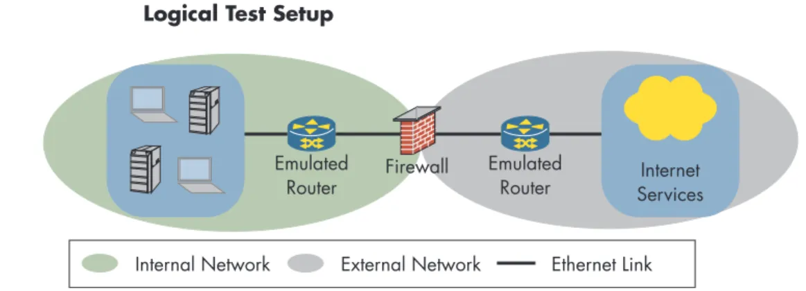
In order to avoid issues pertaining to the neighbor unreachability detection (NUD) mechanism, as mentioned in RFC 5180 section 4, the tester will emulate the subscribers and servers as being one hop beyond the firewall. The following figure shows the logical setup of the test network:
FIGURE 3. Logical Test Setup
Firewall Emulated Router Emulated
Router ServicesInternet
Internal Network External Network Ethernet Link
COEXISTENCE TRAFFIC PATTERNS (CTP)
Throughout this chapter, we will use different ratios of IPv4 and IPv6 traffic, as specified in RFC 5180 section 7. These ratios will be referred to as coexistence traffic patterns or CTP.
TABLE 3. General Parameters – Coexistence Traffic
Coexistence Traffic
Pattern IPv4 Traffic Percentage IPv6 Traffic Percentage
#1 (All IPv4) 100% 0%
#2 90% 10%
#3 50% 50%
#4 10% 90%
IP ADDRESSES The addresses for the testing will be configured from the IANA allocated prefixes for benchmarking: 198.18.0.0/151 and 2001:2/482.
The following table specifies the client and server IP address blocks to be used for load tests.
TABLE 4. General Parameters – IP Addresses
Address Family Client Addresses Server Addresses
IPv4 198.18.128.0/17 198.19.128.0/17 IPv6 2001:2:1::/48 2001:2:2::/48
FILTER LIST The firewall shall be configured with the same rule base for all the tests. The rule base shall contain at least 25 IPv4 and IPv6 rules with the drop action that does not match the generated traffic.
The rule base shall contain one IPv4 and IPv6 rule to allow communication between “Client Addresses” and “Server Addresses”.
REFERENCES “IPv6 Benchmarking Methodology for Network Interconnect Devices”, RFC 5180, May 2008
“Special Use IPv4 Addresses“, RFC 5735, January 2010
“IANA IPv4 Address Space Registry“, http://www.iana.org/assignments/ ipv4-address-space/ipv4-address-space.xml, Retrieved June 15th, 2012 “IANA IPv6 Special Purpose Address Registry“, http://www.iana.org/ assignments/iana-ipv6-special-registry/iana-ipv6-special-registry.xml, Retrieved May 14th, 2012
25
2.1 Layer 3 Throughput
PURPOSE Verify that the maximum throughput of the firewall with each coexistence traffic pattern matches the vendor’s specifications.
DESCRIPTION This test will verify if there are performance differences with respect to layer 3 throughput between IPv4 and IPv6 forwarding. To that end we will use a stateless transport protocol, which doesn’t require additional state tracking by the firewall. Throughput is defined by RFC 2544 as the fastest rate (band-width) at which there is no frame loss observed.
The test equipment will perform binary search to find the maximum throughput which the firewall can forward without dropping packets and measure the latency by maximum throughput.
TEST PARAMETERS • Minimum steady time duration per iteration shall be 60 seconds. • Frame size distribution based on RFC 5180.
• Transport protocol – UDP (or other connectionless transport protocol). • Number of emulated clients.
• Number of emulated servers. TEST PROCEDURE &
EXPECTED RESULTS
• Generate a traffic mix of IPv4 and IPv6 with each of the coexistence traffic patterns according to the vendor specified rate and record packet loss rate.
• Perform binary search to find the highest possible traffic rate without packet loss for each of the coexistence traffic patterns.
REFERENCES “Benchmarking Methodology for Network Interconnect Devices”, RFC 2544, March 1999
“Benchmarking Methodology for Firewall Performance”, RFC 3511, April 2003
“IPv6 Benchmarking Methodology for Network Interconnect Devices“, RFC 5180, May 2008
2.2 TCP Concurrent Connections
PURPOSE Verify that the maximum TCP concurrent connections that the firewall support with each of the coexistence traffic patterns match the vendor’s specifica-tions.
DESCRIPTION The capacity to maintain TCP connections is heavily dependant on the avail-able memory resources. Since IPv6 addresses are 4 times longer than IPv4 addresses, IPv6 connection tracking may impose more stress on the fire-wall’s resources.
TEST PARAMETERS • Steady time duration
• Number of connections per client
• Rate of attempted connections per second • Number of connections per client.
• Number of emulated clients. • Number of emulated servers. • TCP source port range • TCP destination port number TEST PROCEDURE &
EXPECTED RESULTS
• This test shall be performed with each of the coexistence traffic patterns. • Establish TCP connections at the rate specified in the parameters until the
maximum number of concurrent sessions as specified by the vendor are established with each of the coexistence traffic patterns. Record TCP errors such as time outs and retransmissions.
REFERENCES “Benchmarking Methodology for Firewall Performance”, RFC 3511, April 2003
27
2.3 TCP Connection Setup Rate
PURPOSE Determine the maximum supported TCP connection setup rate that the fire-wall supports with each of the coexistence traffic patterns.
DESCRIPTION Establishing new connections with a a high rate is a CPU intensive opera-tion, which requires the firewall to use its resources efficiently. IPv6
processing may impose additional overhead and the implementation might not be as optimized as for IPv4.
TEST PARAMETERS • Steady time duration
• Ramp up and ramp down time.
• Target rate of connections per second. This parameter shall be exceed the vendor’s specifications.
• Number of connections per client. • Number of emulated clients. • Number of emulated servers. • TCP source port range • TCP destination port number TEST PROCEDURE &
EXPECTED RESULTS
• This test shall be performed with each of the coexistence traffic patterns. • Start establishing TCP connections. The attempted rate of connection
shall be determined by the ramp up time and the target rate of connec-tions per second:
– At time t=0, the rate shall be 0 connections/second.
– At time t=[ramp up time] seconds, the rate shall be the target at the rate specified in the parameters.
– During the ramp up period, the attempted rate of connection shall scale linearly. Other scaling may be used – in that case, it must be noted in the test results.
• Record the minimum, maximum and average connection setup rate for the steady duration. If target rate of connections was reached only after the steady duration begun, it must be noted in the test results.
REFERENCES “Benchmarking Methodology for Firewall Performance”, RFC 3511, April 2003
2.4 Application Layer Throughput
PURPOSE Determine the maximum application layer throughput of the firewall with each coexistence traffic pattern.
DESCRIPTION In this test we will emulate a large number of clients and servers using stateful TCP connections in order to assess the application layer throughput of the firewall.
Note, this test requires the prior execution of test case “Layer 3 Throughput“ on page25.
TEST PARAMETERS • Steady time duration
• Ramp up and ramp down time.
• Target throughput rate shall be set according to the results obtained in test case “Layer 3 Throughput“ on page25. Vendor’s specifications shall be used if they are lower that the results obtained in the aforementioned test.
• Number of connections per client. • Number of emulated clients. • Number of emulated servers.
• Application layer protocol (e.g., HTTP) • Transaction size
• TCP source port range • TCP destination port number TEST PROCEDURE &
EXPECTED RESULTS
• This test shall be performed with each of the coexistence traffic patterns. • Generate transactions from the emulated clients to the emulated servers using the application layer protocol defined in the test parameters and the transaction size. Scale the number of transactions to be generated, such that the application layer throughput shall reach the target throughput at t=[ramp up time]:
– At time t=0, the rate shall be 0 bits/second.
– At time t=[ramp up time] seconds, the rate shall be the target at the rate specified in the parameters.
– During the ramp up period, the attempted throughput rate shall scale linearly. Other scaling may be used – in that case, it must be noted in the test results.
• Record the minimum, maximum and average connection setup rate for the steady duration. If target throughput rate was reached only after the steady duration begun, it must be noted in the test results.
• Record TCP errors such as time outs and retransmissions.
REFERENCES “Benchmarking Methodology for Firewall Performance”, RFC 3511, April 2003
29
2.5 Latency
PURPOSE Determine the latency introduced for UDP traffic with each coexistence traffic pattern.
DESCRIPTION While the device is under maximum throughput load, as will be determined by test case 2.4 Application Layer Throughput, additional UDP traffic will be sent and the introduced latency will be measured.
Latency is of special significance to voice and other real time applications. This test will assess the effect IPv6 processing has on the introduced latency. TEST PARAMETERS • Minimum steady time duration per iteration shall be 60 seconds.
• Frame size distribution based on RFC 5180.
• Transport protocol – UDP (or other connectionless transport protocol). • Number of emulated clients.
• Number of emulated servers.
• Maximum throughput load shall be 99% of the maximum observed rate in test case 2.1 Layer 3 Throughput, according to each of the coexis-tence traffic patterns.
• Maximum throughput UDP port numbers/range.
• Extra throughput rate shall be 1% of the maximum observed rate in test case 2.1 Layer 3 Throughput, according to each of the coexistence traffic patterns.
• Extra throughput UDP port numbers/range. This shall differ from
maximum throughput UDP port numbers/range to allow measurement of latency incurred to this stream. Alternatively, an identification of the stream in the payload may be used with the same maximum throughput UDP port numbers/range.
TEST PROCEDURE & EXPECTED RESULTS
• Generate a traffic mix of IPv4 and IPv6 with each of the coexistence traffic patterns according to the maximum throughput load set in the test parameters.
• Generate a traffic mix of IPv4 and IPv6 with each of the coexistence traffic patterns according to the extra throughput rate set in the test parameters. Record minimum, maximum and average latency for the extra throughput rate traffic stream.
REFERENCES “Benchmarking Methodology for Firewall Performance”, RFC 3511, April 2003
2.6 Layer 3 Throughput with IPv6 Extension
Header Chain
PURPOSE Verify that the layer 3 throughput of the firewall when processing various IPv6 extension header chains matches the vendor’s specifications.
DESCRIPTION Extension Headers are an integral part of the IPv6 base specification and processing these headers may require additional resources by the firewall. TEST PARAMETERS • This test shall use the same test parameters as test case 2.1 Layer 3
Throughput.
• The minimal extension header chain list to be tested shall contain: – RFC 5180 recommended header chain (see section 5.3 to RFC 5180) • Hop-by-Hop Options extension header is excluded from this test. • The minimal coexistence traffic patterns list to be used shall contain:
– 100% IPv6 traffic (CTP#5) TEST PROCEDURE &
EXPECTED RESULTS
• For each of the extension header chains used, generate a traffic mix of IPv4 and IPv6 with each of the coexistence traffic patterns defined in the test parameters. Rate shall match the results observed in test case 2.1 Layer 3 Throughput for the particular coexistence traffic pattern. • Perform binary search to find the highest possible traffic rate without
packet loss for each of the coexistence traffic patterns. REFERENCES “Internet Protocol, Version 6 (IPv6)”, RFC 2460, December 1998
“Benchmarking Methodology for Firewall Performance”, RFC 3511, April 2003
“IPv6 Benchmarking Methodology for Network Interconnect Devices“, RFC 5180, May 2008
31
2.7 IPv6 Hop-by-Hop Extension Header
Processing
PURPOSE Verify that the layer 3 throughput of the firewall when processing the Hop-by-Hop IPv6 Next-Header match the vendor’s specifications.
DESCRIPTION The Hop-by-Hop Extension Header requires special processing, as RFC 5180 discusses, and requires therefore separate benchmarking. RFC 5180 states that traffic with the Hop-by-Hop Extension Header could have negative impact on the forwarding node.
TEST PARAMETERS • This test shall use the same test parameters as test case 2.1 Layer 3 Throughput.
• The minimal list for the tested ratios of IPv6 traffic with the Hop-by-Hop options shall be as specified in RFC 5180:
– No IPv6 traffic with Hop-by-Hop extension header (reference test) – 1% of IPv6 traffic with Hop-by-Hop extension header
– 10% of IPv6 traffic with Hop-by-Hop extension header – 50% of IPv6 traffic with Hop-by-Hop extension header
• The minimal coexistence traffic patterns list to be used shall contain: – 100% IPv6 traffic (CTP#5)
TEST PROCEDURE & EXPECTED RESULTS
• For each of the tested ratios used, generate a traffic mix of IPv4 and IPv6 with each of the coexistence traffic patterns defined in the test parame-ters. Rate shall match the results observed in test case 2.1 Layer 3 Throughput for the particular coexistence traffic pattern.
• Perform binary search to find the highest possible traffic rate without packet loss for each of the coexistence traffic patterns and ratios. • Monitor resource utilization (at minimum, CPU and memory utilization) of
the firewall.
REFERENCES “IPv6 Benchmarking Methodology for Network Interconnect Devices“, RFC 5180, May 2008
2.8 IPv6 Fragmentation
PURPOSE Verify that the layer 3 throughput of the firewall when processing valid IPv6 fragmented traffic match the vendor’s specifications.
DESCRIPTION The IPv6 base specification in contrast to the IPv4 base specification does not require special processing of fragments from forwarding IPv6 nodes, an IPv6 firewall. However, as RFC 4942 discusses in section 2, a firewall may collect the fragments before forwarding them for the purpose of deep packet inspection, which may require additional resources from the firewall.
TEST PARAMETERS • Fragmentation profiles, for each profile specifying:
– Number of fragments – may also be specified by a simple distribution/ function or reproducible pseudo-random function.
– Maximum fragment sizes.
• The minimal list of fragmentation profiles shall consist of: – 2 fragments, maximum fragment size of 1280 bytes.
• This test shall use the same test parameters as test case 2.1 Layer 3 Throughput. Frame size distribution may require adjustment based on the list of tested fragmentation types.
• The minimal list for the tested ratios of IPv6 traffic with the Hop-by-Hop options shall be as specified in RFC 5180:
– No IPv6 traffic with fragmentation (reference test) – 1% of IPv6 traffic with fragmentation
– 10% of IPv6 traffic with fragmentation – 50% of IPv6 traffic with fragmentation
• The minimal coexistence traffic patterns list to be used shall contain: – 100% IPv6 traffic (CTP#5)
TEST PROCEDURE & EXPECTED RESULTS
• Perform binary search to find the highest possible traffic rate without packet loss for each of the forwarded fragmentation profiles, tested ratios and coexistence traffic patterns in the test parameters.
REFERENCES “Internet Protocol, Version 6 (IPv6)“, RFC 2460, December 1998 “IPv6 Transition/Coexistence Security Considerations“, RFC 4942, September 2007
“IPv6 Benchmarking Methodology for Network Interconnect Devices“, RFC 5180, May 2008
33
2.9 Malicious IPv6 Fragmentation
PURPOSE Verify that the layer 3 throughput of the firewall when processing valid and invalid (malicious) IPv6 fragmented traffic match the vendor’s specifications and that the invalid traffic is dropped.
DESCRIPTION The firewall must be able to detect and accordingly drop invalid (malicious) traffic also under full load.
TEST PARAMETERS • The minimal list of fragmentation types shall consist of:
– Overlapping fragments; should be dropped, may be forwarded1 – Partial set of fragments; should be dropped.
– Nested fragments; should be dropped. – Tiny fragments; should be forwarded.
• This test shall use the same test parameters as test case 2.1 Layer 3 Throughput. Frame size distribution may require adjustment based on the list of tested fragmentation types.
• The minimal list for the tested ratios of IPv6 traffic with the Hop-by-Hop options shall be as specified in RFC 5180:
– No IPv6 traffic with fragmentation (reference test) – 1% of IPv6 traffic with fragmentation
– 10% of IPv6 traffic with fragmentation – 50% of IPv6 traffic with fragmentation
• The minimal coexistence traffic patterns list to be used shall contain: – 100% IPv6 traffic (CTP#5)
TEST PROCEDURE & EXPECTED RESULTS
• Perform binary search to find the highest possible non-fragmented traffic rate without packet loss for each of the forwarded fragmentation types, tested ratios and coexistence traffic patterns in the test parameters. • 100% traffic loss is expected for fragmented traffic that should be
dropped.
• For fragmented traffic that should be forwarded, note the resulting traffic loss for the fragmented traffic each test permutation.
REFERENCES “Internet Protocol, Version 6 (IPv6)“, RFC 2460, December 1998 “IPv6 Transition/Coexistence Security Considerations“, RFC 4942, September 2007
“IPv6 Benchmarking Methodology for Network Interconnect Devices“, RFC 5180, May 2008.
1. Depending on the overlap pattern and whether the firewall reassembles frag-ments.
2.10 Reset Recovery
PURPOSE Measure the reset recovery time of the firewall for IPv4 and IPv6 traffic. DESCRIPTION To establish that the device restores IPv4 and IPv6 traffic forwarding at the
same time, a reset test as described in RFC 2544 section 26.6 will be performed. The timestamps for the recovery of IPv4 and IPv6 traffic will be recorded separately and compared. In the first part, a software reset test will be performed if applicable. In the second part, a hardware reset will be performed by interrupting the power supply to the firewall.
TEST PARAMETERS • Steady state period duration • Power interruption duration
• Transport protocol – UDP (or other connectionless transport protocol). • Frame size – constant.
TEST PROCEDURE & EXPECTED RESULTS
• Using the results observed in test case 2.1 “Layer 3 Throughput“ for coexistence traffic pattern #3 (50% IPv4, 50% IPv6), generate a traffic mix of 50% IPv4 and 50% IPv6 for the steady state period duration. • Perform software reset on the device.
• Note the timestamp for of the arrival of the first IPv4 and IPv6 packets following the reset.
• Note the timestamp of full recovery (0% traffic loss) for IPv4 and IPv6 packets following the reset.
• The difference between the timestamp of the first packet and full recovery is expected to be 0.
• Compare the difference between IPv4 and IPv6 timestamps of the arrival of the first packet following the reset.
• Perform test again, using hardware reset instead of software reset. REFERENCES “Benchmarking Methodology for Network Interconnect Devices”, RFC
35
2.11 System Overload Recovery
PURPOSE Observe the time the firewall requires to recover from an overload condi-tion.
DESCRIPTION In this test we will overload the firewall with traffic exceeding the processing capability by sending traffic at 110% of the maximum throughput rate as determined by test case 2.1 “Layer 3 Throughput“ for 60 seconds. We will then reduce the rate to 50% and record the time of the last frame loss. See also RFC 2544, section 26.5.
TEST PARAMETERS • Overload period duration • Recovery period duration
• Transport protocol – UDP (or other connectionless transport protocol). • Frame size – constant
• Overload period traffic rate – 110% of observed maximum throughput rate.
• Recovery period traffic rate – 50% of observed maximum throughput rate.
TEST PROCEDURE & EXPECTED RESULTS
• Using the results observed in test case 2.1 “Layer 3 Throughput“, generate a traffic mix of IPv4 and IPv6 with each of the coexistence traffic patterns at the overload period traffic rate for the overload period duration.
• Traffic loss during the overload period is expected to be at least 9%. • After the overload period duration expired, reduce traffic instantaneously
to the rate matching the recovery period traffic rate. Stop traffic after the recovery period duration expired.
• Note the first timestamp in the recovery period where no traffic loss is observed. No traffic loss is expected following this event. The timestamps may differ between IPv4 traffic and IPv6 traffic.
• Time to recovery shall be calculated as the difference between the begin-ning of the recovery period and the timestamp noted for each address family and for each coexistence traffic pattern.
REFERENCES “Benchmarking Methodology for Network Interconnect Devices”, RFC 2544, March 1999
This chapter is dedicated to the verification of the IDS’ ability to detect various IPv6 attacks performed on the LAN.
Test Setup
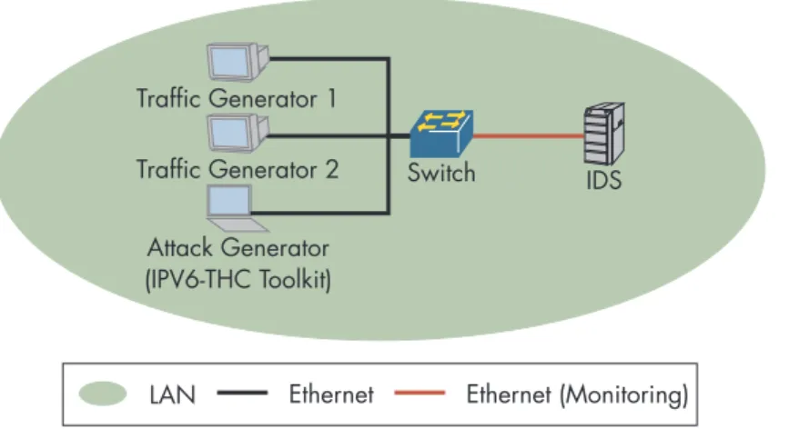
In this chapter we will used one test setup to run all of the IPv6 IDS tests.The attack and traffic generators will be connected to the switch, with all the ports configured without tagging on the same VLAN (access ports). The IDS sensor will be connected to a monitoring port configured to mirror all the traffic from the ports connecting the attack and traffic generators.
FIGURE 4. Physical Test Setup
LAN Ethernet Attack Generator (IPV6-THC Toolkit) IDS Traffic Generator 2 Traffic Generator 1 Switch Ethernet (Monitoring)
37 HEADER PROFILES The IDS should be able to detect the attacks, even if the attacker attempts to
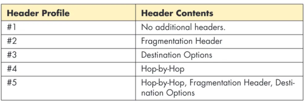
conceal them using additional headers as discussed in draft-ietf-v6ops-ra-guard-implementation-02 section 2. The following table specifies the header profiles to be used with tests in this chapter. The header contents exclude the base IPv6 header and the last next-header (upper layer) which will be speci-fied in each test.
TABLE 5. Header Profiles
Header Profile Header Contents
#1 No additional headers. #2 Fragmentation Header #3 Destination Options #4 Hop-by-Hop
#5 Hop-by-Hop, Fragmentation Header, Desti-nation Options
REFERENCES “RA-Guard Implementation Advice“, Work in Progress, draft-ietf-v6ops-ra-guard-implementation-07, Expires May 18, 2013
3.1 Spoofed Neighbor Discovery Messages
PURPOSE Verify that the IDS is able to detect spoofed Neighbor Discovery (NA) messages.
DESCRIPTION By spoofing Neighbor Discovery (NA) messages, an attacker can redirect all the traffic on the local network to an arbitrary layer 2 destination. This test will verify that the IDS detects the attack and generates an alarm in response. This attack may be performed using the “parasite6” tool from the IPV6-THC toolbox.
TEST PARAMETERS • Destination MAC address (i.e. “fake MAC”) shall be set to the attack generator’s MAC address.
• Minimal wait time shall be set to 60 seconds (2 times REACHABLE_TIME from RFC 4861).
TEST PROCEDURE & EXPECTED RESULTS
• Perform this test with each of the header profiles (see table 5 “Header Profiles“).
• Verify no traffic is being sent between traffic generators 1 and 2. • After minimal wait time expired, generate traffic between the two traffic
generators on the segment. The IDS is expected to generate an alarm in response.
REFERENCES “Neighbor Discovery in IPv6“, RFC 4861, September 2007
39
3.2 Duplicate Address Detection DoS
PURPOSE Verify that the IDS is able to detect Neighbor Discovery DoS.
DESCRIPTION When an IPv6 node performs DAD, it sends a solicitation to the address. If the address is already in use, it will receive an advertisement from the node currently holding the address. An attacker can reply to any solicitation, effectively preventing an IPv6 node which performs DAD to join the local network segment. This test verifies that the IDS detects this attack and raises an alarm in response. This attack may be performed using the “dos-new-ip6” tool from the IPV6-THC toolbox.
TEST PARAMETERS • A list of IPv6 host addresses on the segment. TEST PROCEDURE &
EXPECTED RESULTS
• Run the “dos-new-ip6” tool.
• Configure traffic generator 1 with the IPv6 host addresses list. Initiate DAD on the traffic generator.
• The “dos-new-ip6” shall generate a spoofed Neighbor Advertisement (NA) to every DAD attempt. IDS shall generate an alarm describing the event.
REFERENCES “Neighbor Discovery in IPv6“, RFC 4861, September 2007
3.3 Spoofed Redirect Message
PURPOSE Verify that the IDS is able to detect rogue ICMPv6 redirect messages. DESCRIPTION ICMPv6 redirect messages may be sent by a router to inform a node that a
better first-hop node on the path to the destination is available. An attacker can generate redirect messages which may cause the attack’s target node to send traffic to an arbitrary address. This test will verify that the IDS can detect this attack and generate an alarm in response. This attack may be performed using the “redir6” tool from the IPV6-THC toolbox.
Note: it may be required to configure the router address on the IDS before performing this test.
TEST PARAMETERS • The following IPv6 host address shall be determined: – Attack target
– Redirected address, the address to be redirected to “new router address”
– Router address – New router address TEST PROCEDURE &
EXPECTED RESULTS
• Generate a ICMPv6 redirect using the “redir6” tool using the test param-eters.
• IDS shall generate an alarm indicating a rouge ICMPv6 redirect.
REFERENCES “Neighbor Discovery in IPv6“, RFC 4861, September 2007
41
3.4 Spoofed Zero-Lifetime Router
Advertise-ment Messages
PURPOSE Verify that the IDS is able to detect spoofed ICMPv6 router advertisement messages with router lifetime of zero.
DESCRIPTION A router advertisement with a zero lifetime is used to indicate that a prefix has been withdrawn by the router. An attacker can use this to “kill” the router on the segment, as discussed in RFC 3756 section 4.2.2. This test will verify that the IDS can detect this attack and generate an alarm in response. This attack may be performed using the “kill_router6” tool from the IPV6-THC toolbox.
TEST PARAMETERS • Attack target – IPv6 host address. TEST PROCEDURE &
EXPECTED RESULTS
• For each of the “Header Profiles“ on page 37, generate a rouge router advertisement using the “kill_router6” tool.
• The IDS should generate an alarm for each header profile.
REFERENCES “IPv6 Neighbor Discovery (ND) Trust Models and Threats“, RFC 3756, May 2004
“Neighbor Discovery in IPv6“, RFC 4861, September 2007
3.5 Router Advertisements Flooding
PURPOSE Verify that the IDS detects Router Advertisements (RAs) flooding.
DESCRIPTION Flooding a LAN with random RA messages may cause IPv6 nodes to contin-uously update their entries, which may lead to a high CPU utilization and unresponsiveness of the affected nodes. This test will verify that the IDS can detect and generate an alert in response to this attack. We will also test that adding additional headers to the flooded RA messages does not evade detection by the IDS.
TEST PARAMETERS • Destination address – ff02::1 (all-nodes link-local multicast). • Bottom extension header – ICMPv6 (58).
• ICMPv6 message type – 134, router advertisement (RA). • Number of MAC addresses.
• Number of IPv6 addresses.
• Reproducible pseudo-random MAC address pattern/function. • Reproducible pseudo-random IPv6 address pattern/function. • Test duration.
TEST PROCEDURE & EXPECTED RESULTS
• Start monitor IDS resources for at least 5 minutes before traffic genera-tion.
• For each of the “Header Profiles“ on page 37, generate router advertise-ment (RA) packets using the number of MAC and IPv6 addresses. The addresses shall be generated pseudo-randomly using the predefined pattern/function.
• The IDS should generate an alarm for each header profile.
• Continue monitoring IDS resources for at least 5 minutes after traffic generation stopped.
• IDS CPU utilization should not reach 100%.
• Results shall include the CPU utilization to time graph, including time-stamps of each traffic generation start and stop event (per header profile).
REFERENCES “Neighbor Discovery in IPv6“, RFC 4861, September 2007
“ICMPv6 Router Announcement flooding denial of service affecting multiple systems“, http://www.mh-sec.de/downloads/mh-RA_flooding_CVE-2010-multiple.txt, Retrieved May 4th, 2012
43
3.6 Neighbor Advertisements Flooding
PURPOSE Verify that the IDS detects Neighbor Advertisements (NAs) flooding. DESCRIPTION Flooding a LAN with random NA messages may cause IPv6 NUD table to
exhaust and may lead to a high CPU utilization and unresponsiveness of the affected nodes. This test will verify that the IDS can detect and generate an alert in response to this attack. We will also test that adding additional headers to the flooded NA messages does not evade detection by the IDS. TEST PARAMETERS • Destination address – ff02::1 (all-nodes link-local multicast).
• Bottom extension header – ICMPv6 (58).
• ICMPv6 message type – 136, router advertisement (NA). • Number of MAC addresses.
• Number of IPv6 addresses.
• Reproducible pseudo-random MAC address pattern/function. • Reproducible pseudo-random IPv6 address pattern/function. • Test duration.
TEST PROCEDURE & EXPECTED RESULTS
• Start monitor IDS resources for at least 5 minutes before traffic genera-tion.
• For each of the “Header Profiles“ on page 37, generate neighbor adver-tisement (NA) packets using the number of MAC and IPv6 addresses. The addresses shall be generated pseudo-randomly using the predefined pattern/function.
• The IDS should generate an alarm for each header profile.
• Continue monitoring IDS resources for at least 5 minutes after traffic generation stopped.
• IDS CPU utilization should not reach 100%.
• Results shall include the CPU utilization to time graph, including time-stamps of each traffic generation start and stop event (per header profile).