NSX Administration Guide
NSX 6.1 for vSphere
This document supports the version of each product listed and
supports all subsequent versions until the document is
replaced by a new edition. To check for more recent editions
of this document, see
http://www.vmware.com/support/pubs
.
You can find the most up-to-date technical documentation on the VMware Web site at:
http://www.vmware.com/support/
The VMware Web site also provides the latest product updates.
If you have comments about this documentation, submit your feedback to:
Copyright © 2010 – 2015 VMware, Inc. All rights reserved. Copyright and trademark information.
VMware, Inc. 3401 Hillview Ave. Palo Alto, CA 94304 www.vmware.com
NSX Administration Guide 11
1
Overview of NSX 13
NSX Components 14 NSX Services 16
2
Logical Switches 19
Create a Logical Switch 20
Connect Virtual Machines to a Logical Switch 23 Test Logical Switch Connectivity 23
Prevent Spoofing on a Logical Switch 24 Edit a Logical Switch 24
Working with Transport Zones 24 Logical Switch Scenario 26
3
L2 Bridges 31
Add L2 Bridge 32
4
Logical Router 33
Specify Global Configuration 33 Add a Static Route 34
Configure OSPF 35 Configure BGP 36
Configure IS-IS Protocol 37 Configure Route Redistribution 38
5
Logical Firewall 41
Distributed Firewall 41 Edge Firewall 42
Working with Firewall Rules 42 Working with Firewall Rule Sections 50 Working with Firewall Configurations 51
Excluding Virtual Machines from Firewall Protection 52 Using SpoofGuard 53
View Firewall CPU and Memory Threshold Events 56 Firewall Logs 56
Working with Local Rules 56
6
Virtual Private Networks (VPN)s 65
SSL VPN-Plus Overview 65 IPSec VPN Overview 86
L2 VPN Overview 90
7
Logical Load Balancer 97
Set Up Load Balancing 97
Load Balance Web Servers using NTLM Authentication 107 Working with Application Profiles 107
Working with Service Monitors 108 Working with Server Pools 109 Working with Virtual Servers 109 Working with Application Rules 110
8
Other Edge Services 111
Managing DHCP Service 111 Configuring DHCP Relay 114 Configure DNS Servers 115
9
Service Composer 117
Using Service Composer 118
Graphical View of Service Composer 124 Export a Service Composer Configuration 127 Import a Service Composer Configuration 127 Working with Security Tags 128
Viewing Effective Services 130 Working with Security Policies 131 Edit a Security Group 132
Service Composer Scenarios 132
10
Data Security 137
NSX Data Security User Roles 137 Defining a Data Security Policy 137 Running a Data Security Scan 139 Viewing and Downloading Reports 140 Creating Regular Expressions 140
11
Network Extensibility 141
Distributed Service Insertion 142 Edge-Based Service Insertion 142 Integrating Third Party Services 142
Consuming Vendor Services through Service Composer 142
Redirecting Traffic to a Vendor Solution through Logical Firewall 143 Using a Partner Load Balancer 143
12
User Management 145
Configure Single Sign On 145 Managing User Rights 146
Managing the Default User Account 147 Assign a Role to a vCenter User 147 Edit a User Account 149
Change a User Role 150
Disable or Enable a User Account 150 Delete a User Account 150
13
Network and Security Objects 153
Working with IP Address Groups 153 Working with MAC Address Groups 154 Working with IP Pools 155
Working with Security Groups 156
Working with Services and Service Groups 158
14
Operations and Management 161
System Events and Audit Logs 161 Management System Settings 165
Working with Active Directory Domains 168 NSX Edge Operations 170
Backing Up NSX Manager Data 182 Flow Monitoring 184
Activity Monitoring 190
Guest Introspection Events and Alarms 199
15
NSX Edge VPN Configuration Examples 203
Terminology 204
IKE Phase 1 and Phase 2 204
Configuring IPSec VPN Service Example 206 Using a Cisco 2821 Integrated Services Router 207 Using a Cisco ASA 5510 210
Configuring a WatchGuard Firebox X500 212
Troubleshooting NSX Edge Configuration Example 213
16
Data Security Regulations 223
Arizona SB-1338 225 ABA Routing Numbers 225
Australia Bank Account Numbers 225
Australia Business and Company Numbers 225 Australia Medicare Card Numbers 226
Australia Tax File Numbers 226 California AB-1298 226
California SB-1386 227
Canada Social Insurance Numbers 227 Canada Drivers License Numbers 227 Colorado HB-1119 228
Connecticut SB-650 228 Credit Card Numbers 228 Custom Account Numbers 228 EU Debit Card Numbers 229
FERPA (Family Educational Rights and Privacy Act) 229 Florida HB-481 229
France IBAN Numbers 229
France National Identification Numbers Policy 229 Georgia SB-230 Policy 230
Germany BIC Numbers Policy 230
Germany Driving License Numbers Policy 230 Germany IBAN Numbers Policy 230
Germany National Identification Numbers Policy 230 Germany VAT Numbers Policy 230
Hawaii SB-2290 Policy 231
HIPAA (Healthcare Insurance Portability and Accountability Act) Policy 231 Idaho SB-1374 Policy 231
Illinois SB-1633 232 Indiana HB-1101 Policy 232
Italy Driving License Numbers Policy 232 Italy IBAN Numbers Policy. 232
Italy National Identification Numbers Policy 232 Kansas SB-196 Policy 233
Louisiana SB-205 Policy 233 Maine LD-1671 Policy 233 Massachusetts CMR-201 234 Minnesota HF-2121 234 Montana HB-732 234
Netherlands Driving Licence Numbers 234 Nevada SB-347 235
New Hampshire HB-1660 235 New Jersey A-4001 235 New York AB-4254 236
New Zealand Inland Revenue Department Numbers 236 New Zealand Ministry of Health Numbers 236
Ohio HB-104 236 Oklahoma HB-2357 237
Patient Identification Numbers 237
Payment Card Industry Data Security Standard (PCI-DSS) 237 Texas SB-122 237
UK BIC Numbers 238
UK Driving Licence Numbers 238 UK IBAN Numbers 238
UK National Health Service Numbers 238 UK National Insurance Numbers (NINO) 238 UK Passport Numbers 238
US Drivers License Numbers 239 US Social Security Numbers 239 Utah SB-69 239
Vermont SB-284 239 Washington SB-6043 240
Data Security Content Blades 240
17
Data Security Content Blades 261
Admittance and Discharge Dates Content Blade 264 Alabama Drivers License Content Blade 264 Alaska Drivers License Content Blade 265 Alberta Drivers Licence Content Blade 265 Alaska Drivers License Content Blade 265 Alberta Drivers Licence Content Blade 265 American Express Content Blade 265 Arizona Drivers License Content Blade 265 Arkansas Drivers License Content Blade 266 Australia Bank Account Number Content Blade 266 Australia Business Number Content Blade 266 Australia Company Number Content Blade 266 Australia Medicare Card Number Content Blade 266 Australia Tax File Number Content Blade 266 California Drivers License Number Content Blade 267 Canada Drivers License Number Content Blade 267 Canada Social Insurance Number Content Blade 267 Colorado Drivers License Number Content Blade 267 Connecticut Drivers License Number Content Blade 267 Credit Card Number Content Blade 267
Credit Card Track Data Content Blade 267 Custom Account Number Content Blade 268
Delaware Drivers License Number Content Blade 268 EU Debit Card Number Content Blade 268
Florida Drivers License Number Content Blade 268 France Driving License Number Content Blade 268 France BIC Number Content Blade 268
France IBAN Number Content Blade 268
France National Identification Number Content Blade 269 France VAT Number Content Blade 269
Georgia Drivers License Number Content Blade 269 Germany BIC Number Content Blade 269
Germany Driving License Number Content Blade 269 Germany IBAN Number Content Blade 269
Germany National Identification Numbers Content Blade 269 Germany Passport Number Content Blade 270
Germany VAT Number Content Blade 270 Group Insurance Numbers Content Blade 270 Hawaii Drivers License Number Content Blade 270 Italy National Identification Numbers Content Blade 270 Health Plan Beneficiary Numbers 271
Idaho Drivers License Number Content Blade 271 Illinois Drivers License Number Content Blade 271 Indiana Drivers License Number Content Blade 271 Iowa Drivers License Number Content Blade 271 Index of Procedures Content Blade 271
Italy Driving License Number Content Blade 272 Italy IBAN Number Content Blade 272
Kansas Drivers License Number Content Blade 273 Kentucky Drivers License Number Content Blade 273 Louisiana Drivers License Number Content Blade 273 Maine Drivers License Number Content Blade 273 Manitoba Drivers Licence Content Blade 273
Maryland Drivers License Number Content Blade 274 Massachusetts Drivers License Number Content Blade 274 Michigan Drivers License Number Content Blade 274 Minnesota Drivers License Number Content Blade 274 Mississippi Drivers License Number Content Blade 274 Missouri Drivers License Number Content Blade 274 Montana Drivers License Number Content Blade 274 NDC Formulas Dictionary Content Blade 274 Nebraska Drivers License Number Content Blade 275 Netherlands Driving Licence Number Content Blade 275 Netherlands IBAN Number Content Blade 275
Netherlands National Identification Numbers Content Blade 275 Netherlands Passport Number Content Blade 276
Nevada Drivers License Number Content Blade 276 New Brunswick Drivers Licence Content Blade 276
New Hampshire Drivers License Number Content Blade 276 New Jersey Drivers License Number Content Blade 276 New Mexico Drivers License Number Content Blade 276 New York Drivers License Number Content Blade 276
New Zealand Health Practitioner Index Number Content Blade 277 New Zealand Inland Revenue Department Number 277
New Zealand National Health Index Number Content Blade 277 Newfoundland and Labrador Drivers Licence Content Blade 277 North Carolina Drivers License Number Content Blade 277 North Dakota Drivers License Number Content Blade 277 Nova Scotia Drivers Licence Content Blade 277
Ohio Drivers License Number Content Blade 277 Oklahoma License Number Content Blade 278 Ontario Drivers Licence Content Blade 278 Oregon License Number Content Blade 278 Patient Identification Numbers Content Blade 278 Pennsylvania License Number Content Blade 278 Prince Edward Island Drivers Licence Content Blade 278 Protected Health Information Terms Content Blade 278 Quebec Drivers Licence Content Blade 279
Rhode Island License Number Content Blade 279 Saskatchewan Drivers Licence Content Blade 279 SIN Formatted Content Blade 279
SIN Unformatted Content Blade 279 SSN Formatted Content Blade 279 SSN Unformatted Content Blade 280
South Carolina License Number Content Blade 280 South Dakota License Number Content Blade 280 Spain National Identification Number Content Blade 280
Spain Passport Number Content Blade 280 Spain Social Security Number Content Blade 280 Sweden IBAN Number Content Blade 280 Sweden Passport Number Content Blade 281 Tennessee License Number Content Blade 281 UK BIC Number Content Blade 281
UK Driving License Number Content Blade 281 UK IBAN Number Content Blade 282
UK National Health Service Number Content Blade 282 UK NINO Formal Content Blade 282
UK Passport Number Content Blade 282 Utah License Number Content Blade 283 Virginia License Number Content Blade 283 Visa Card Number Content Blade 283
Washington License Number Content Blade 283 Wisconsin License Number Content Blade 283 Wyoming License Number Content Blade 283
18
File Formats Supported by Data Security 285
Index 291
The NSX Administration Guide describes how to configure, monitor, and maintain the VMware® NSX™ system by using the NSX Manager user interface and the vSphere Web Client. The information includes step-by-step configuration instructions, and suggested best practices.
Intended Audience
This manual is intended for anyone who wants to install or use NSX in a VMware vCenter environment. The information in this manual is written for experienced system administrators who are familiar with virtual machine technology and virtual datacenter operations. This manual assumes familiarity with VMware Infrastructure 5.x, including VMware ESX, vCenter Server, and the vSphere Web Client.
Overview of NSX
1
IT organizations have gained significant benefits as a direct result of server virtualization. Server
consolidation reduced physical complexity, increased operational efficiency and the ability to dynamically re-purpose underlying resources to quickly and optimally meet the needs of increasingly dynamic business applications.
VMware’s Software Defined Data Center (SDDC) architecture is now extending virtualization technologies across the entire physical data center infrastructure. VMware NSX®, the network virtualization platform, is a key product in the SDDC architecture. With NSX, virtualization delivers for networking what it has already delivered for compute and storage. In much the same way that server virtualization
programmatically creates, snapshots, deletes and restores software-based virtual machines (VMs), NSX network virtualization programmatically creates, snapshots, deletes, and restores software-based virtual networks. The result is a completely transformative approach to networking that not only enables data center managers to achieve orders of magnitude better agility and economics, but also allows for a vastly simplified operational model for the underlying physical network. With the ability to be deployed on any IP network, including both existing traditional networking models and next-generation fabric architectures from any vendor, NSX is a completely non-disruptive solution. In fact, with NSX, the physical network infrastructure you already have is all you need to deploy a software-defined data center.
Application Application
Workload Workload
Workload
x86 environment
Virtual machine
Requirement: x86
Physical compute and memory
Decoupled
Virtual network
L2, L3, L4-7 network service
Server hypervisor Network virtualization platform
Physical network Requirement: IP transport Virtual
machine networkVirtual
Virtual
machine networkVirtual
The figure above draws an analogy between compute and network virtualization. With server
virtualization, a software abstraction layer (server hypervisor) reproduces the familiar attributes of an x86 physical server (for example, CPU, RAM, Disk, NIC) in software, allowing them to be programmatically assembled in any arbitrary combination to produce a unique VM in a matter of seconds.
With network virtualization, the functional equivalent of a network hypervisor reproduces the complete set of Layer 2 through Layer 7 networking services (for example, switching, routing, access control, firewalling, QoS, and load balancing) in software. As a result, these services can be programmatically assembled in any arbitrary combination, to produce unique, isolated virtual networks in a matter of seconds.
With network virtualization, benefits similar to server virtualization are derived. For example, just as VMs are independent of the underlying x86 platform and allow IT to treat physical hosts as a pool of compute capacity, virtual networks are independent of the underlying IP network hardware and allow IT to treat the physical network as a pool of transport capacity that can be consumed and repurposed on demand. Unlike legacy architectures, virtual networks can be provisioned, changed, stored, deleted, and restored
programmatically without reconfiguring the underlying physical hardware or topology. By matching the capabilities and benefits derived from familiar server and storage virtualization solutions, this
transformative approach to networking unleashes the full potential of the software-defined data center. NSX can be configured through the vSphere Web Client, a command-line interface (CLI), and a REST API. This chapter includes the following topics:
n “NSX Components,” on page 14 n “NSX Services,” on page 16
NSX Components
This section describes the components of the NSX solution.
NSX Edge
vDS
VXLAN Distributed Logical Router
Firewall Hypervisor Extension Modules
NSX Manager
NSX vSwitch
NSX Controller CMP
Consumption
Management plane
Control plane
Run-time state
Data Plane
The NSX Data plane consists of the NSX vSwitch, which is based on the vSphere Distributed Switch (VDS) with additional components to enable services. Kernel modules (VIBs) run within the hypervisor kernel to provide services such as distributed routing and logical firewall and to enable VXLAN bridging capabilities. The NSX vSwitch (vDS-based) abstracts the physical network and provides access-level switching in the hypervisor. It is central to network virtualization because it enables logical networks that are independent of physical constructs, such as VLANs. Some of the benefits of the vSwitch are:
n Support for overlay networking with protocols (such as VXLAN) and centralized network
configuration. Overlay networking enables the following capabilities:
n Creation of a flexible logical Layer 2 (L2) overlay over existing IP networks on existing physical
infrastructure without the need to re-architect any of the data center networks
n Provision of communication (east–west and north–south), while maintaining isolation between
tenants
n Application workloads and virtual machines that are agnostic of the overlay network and operate
as if they were connected to a physical L2 network
n Facilitates massive scale of hypervisors
n Multiple features—such as Port Mirroring, NetFlow/IPFIX, Configuration Backup and Restore,
Network Health Check, QoS, and LACP—provide a comprehensive toolkit for traffic management, monitoring, and troubleshooting within a virtual network
Additionally, the data plane consists of gateway devices that can provide L2 bridging from the logical networking space (VXLAN) to the physical network (VLAN). The gateway device is typically an NSX Edge virtual appliance. NSX Edge offers L2, L3, perimeter firewall, load balancing, and other services such as SSL VPN and DHCP.
Control Plane
The NSX control plane runs in the NSX controller. NSX controller is an advanced distributed state management system that controls virtual networks and overlay transport tunnels. It is the central control point for all logical switches within a network and maintains information about all virtual machines, hosts, logical switches, and VXLANs.
The controller does not have any dataplane traffic passing through it. Controller nodes are deployed in a cluster of odd-numbered members to enable high-availability and scale. Any failure of the controller nodes does not impact any data-plane traffic.
Management Plane
The NSX management plane is built by the NSX Manager, the centralized network management component of NSX. It provides the single point of configuration and REST API entry-points.
The NSX Manager is installed as a virtual appliance on any ESX™ host in your vCenter Server environment.
Consumption Platform
The consumption of NSX can be driven directly through the NSX Manager user interface. In a vSphere environment, this is available in the vSphere Web Client. Typically end users tie network virtualization to their cloud management platform for deploying applications. NSX provides rich integration into virtually any CMP through REST APIs. Out-of-the-box integration is also available through VMware vCloud Automation Center, vCloud Director, and OpenStack with the Neutron plug-in for NSX.
NSX Services
The NSX components work together to provide the following functional services.
Logical Switches
A cloud deployment or a virtual data center has a variety of applications across multiple tenants. These applications and tenants require isolation from each other for security, fault isolation, and non-overlapping IP addresses. The NSX logical switch creates logical broadcast domains or segments to which an application or tenant virtual machine can be logically wired. This allows for flexibility and speed of deployment while still providing all the characteristics of a physical network's broadcast domains (VLANs) without physical Layer 2 sprawl or spanning tree issues.
A logical switch is distributed and can span arbitrarily large compute clusters. This allows for virtual machine mobility (vMotion) within the data center without limitations of the physical Layer 2 (VLAN) boundary. The physical infrastructure is not constrained by MAC/FIB table limits, because the logical switch contains the broadcast domain in software.
Logical Routers
Dynamic routing provides the necessary forwarding information between Layer 2 broadcast domains, thereby allowing you to decrease the size of Layer 2 broadcast domains and improve network efficiency and scale. NSX extends this intelligence to where the workloads reside for East-West routing. This allows more direct VM-to-VM communication without the costly or timely need to extend hops. At the same time, NSX logical routers provide North-South connectivity, thereby enabling tenants to access public networks.
Logical Firewall
Logical Firewall provides security mechanisms for dynamic virtual data centers. The Distributed Firewall component of Logical Firewall allows you to segment virtual datacenter entities like virtual machines based on VM names and attributes, user identity, vCenter objects like datacenters, and hosts, as well as traditional networking attributes like IP addresses, VLANs, and so on. The Edge Firewall component helps you meet key perimeter security requirements, such as building DMZs based on IP/VLAN constructs, tenant-to-tenant isolation in multi-tenant virtual data centers, Network Address Translation (NAT), partner (extranet) VPNs, and user-based SSL VPNs.
The Flow Monitoring feature displays network activity between virtual machines at the application protocol level. You can use this information to audit network traffic, define and refine firewall policies, and identify threats to your network.
Logical Virtual Private Networks (VPN)s
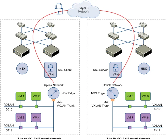
SSL VPN-Plus allows remote users to access private corporate applications. IPSec VPN offers site-to-site connectivity between an NSX Edge instance and remote sites. L2 VPN allows you to extend your datacenter by allowing virtual machines to retain network connectivity across geographical boundaries.
Logical Load Balancer
The NSX Edge load balancer enables network traffic to follow multiple paths to a specific destination. It distributes incoming service requests evenly among multiple servers in such a way that the load distribution is transparent to users. Load balancing thus helps in achieving optimal resource utilization, maximizing throughput, minimizing response time, and avoiding overload. NSX Edge provides load balancing up to Layer 7.
Service Composer
Service Composer helps you provision and assign network and security services to applications in a virtual infrastructure. You map these services to a security group, and the services are applied to the virtual machines in the security group.
Data Security provides visibility into sensitive data stored within your organization's virtualized and cloud environments. Based on the violations reported by NSX Data Security, you can ensure that sensitive data is adequately protected and assess compliance with regulations around the world.
NSX Extensibility
VMware partners can integrate their solutions with the NSX platform, thus enabling customers to have an integrated experience across VMware products and partner solutions. Data center operators can provision complex, multi-tier virtual networks in seconds, independent of the underlying network topology or components.
Logical Switches
2
A cloud deployment or a virtual data center has a variety of applications across multiple tenants. These applications and tenants require isolation from each other for security, fault isolation, and avoidance of overlapping IP addressing issues. The NSX logical switch creates logical broadcast domains or segments to which an application or tenant virtual machine can be logically wired. This allows for flexibility and speed of deployment while still providing all the characteristics of a physical network's broadcast domains (VLANs) without physical Layer 2 sprawl or spanning tree issues.
A logical switch is distributed and can span arbitrarily large compute clusters. This allows for virtual machine mobility (vMotion) within the datacenter without the limitations of the physical Layer 2 (VLAN) boundary. The physical infrastructure is not constrained by MAC/FIB table limits because the logical switch contains the broadcast domain in software.
A logical switch is mapped to a unique VXLAN, which encapsulates the virtual machine traffic and carries it over the physical IP network.
VM VM VM
VM VM
Logical switch 1
Logical switch 2
vSphere Distributed Switch NSX Manager
NSX Controller
The NSX controller is the central control point for all logical switches within a network and maintains information aboutall virtual machines, hosts, logical switches, and VXLANs. The controller supports two new logical switch control plane modes, Unicast and Hybrid. These modes decouple NSX from the physical network. VXLANs no longer require the physical network to support multicast in order to handle the Broadcast, Unknown unicast, and Multicast (BUM) traffic within a logical switch. The unicast mode replicates all the BUM traffic locally on the host and requires no physical network configuration. In the hybrid mode, some of the BUM traffic replication is offloaded to the first hop physical switch to achieve better performance. This mode requires IGMP snooping to be enabled the first hop physical switch. Virtual machines within a logical switch can use and send any type of traffic including IPv6 and multicast.
You can extend a logical switch to a physical device by adding an L2 bridge. See Chapter 3, “L2 Bridges,” on page 31.
You must have the Super Administrator or Enterprise Administrator role permissions to manage logical switches.
This chapter includes the following topics:
n “Create a Logical Switch,” on page 20
n “Connect Virtual Machines to a Logical Switch,” on page 23 n “Test Logical Switch Connectivity,” on page 23
n “Prevent Spoofing on a Logical Switch,” on page 24 n “Edit a Logical Switch,” on page 24
n “Working with Transport Zones,” on page 24 n “Logical Switch Scenario,” on page 26
Create a Logical Switch
Prerequisitesn You have the Super Administrator or Enterprise Administrator role permission to configure and
manage logical switches.
n You have prepared clusters that are to be part of the logical switch. See Prepare Clusters for Network
Virtualization in the NSX Installation and Upgrade Guide.
n You have configured VXLAN on the appropriate clusters. See Configure VXLAN Transport Parameters in
the NSX Installation and Upgrade Guide.
n You have the minimum required software versions. See System Requirements in the NSX Installation and
Upgrade Guide.
n VXLAN UDP port is opened on firewall rules (if applicable). The VXLAN UDP port can be configured
through the API. The default is 8472.
n Port 80 is opened from NSX Manager to the hosts. This is used to download the vib/agent. n Physical infrastructure MTU is at least 50 bytes more than the MTU of the virtual machine vNIC. n Managed IP address is set for each vCenter Server in the vCenter Server Runtime Settings. See vCenter
Server and Host Management.
n DHCP is available on VXLAN transport VLANs if you are using DHCP for IP assignment for
VMKNics.
n A consistent distributed virtual switch type (vendor, and so on) and version is being used across a
given transport zone. Inconsistent switch types can lead to undefined behavior in your logical switch.
n You have configured an appropriate LACP teaming policy and connected physical NICs to the ports.
For more information on teaming modes, refer to the VMware vSphere documentation.
n 5-tuple hash distribution is enabled for Link Aggregation Control Protocol (LACP).
n For multicast mode, multicast routing is enabled if VXLAN traffic is traversing routers. You have
aquired a multicast address range from your network administrator.
n Port 1234 (the default controller listening port) is opened on firewall for the ESX host to communicate
n (Recommended) For multicast and hybrid modes, you have enabled IGMP snooping on the L2 switches
to which VXLAN participating hosts are attached. If IGMP snooping is enabled on L2, IGMP querier must be enabled on the router or L3 switch with connectivity to multicast enabled networks.
Add a Transport Zone
A transport zone defines the span of a logical switch. It can span one or more vSphere clusters. An NSX environment can contain one or more transport zones based on your requirements.
If a vDS spans more than one cluster and the transport zone is based on one of these clusters, the logical switch associated with this transport zone can access virtual machines within all clusters spanned by the vDS. In other words, this transport zone will not be able to constrain the logical switch span to a single cluster.
If this logical switch is later connected to a distributed router, you must ensure that the router instances are created only in the cluster included in the transport zone to avoid any Layer 3 issues.
Procedure
1 In the vSphere Web Client, click Networking & Security > Installation. 2 Click Logical Network Preparation and then click Transport Zones. 3 Click the New Transport Zone icon.
4 In the New Transport Zone dialog box, type a name and description for the transport zone.
5 Depending on whether you have a controller node in your environment, or you want to use multicast addresses, select the control plane mode.
n Multicast: Multicast IP addresses in the physical network are used for the control plane. This mode
is recommended only when you are upgrading from older VXLAN deployments. Requires PIM/IGMP in the physical network.
n Unicast : The control plane is handled by an NSX controller. All unicast traffic leverages headend
replication. No multicast IP addresses or special network configuration is required.
n Hybrid : The optimized unicast mode. Offloads local traffic replication to the physical network (L2
multicast). This requires IGMP snooping on the first-hop switch, but does not require PIM. The first-hop switch handles traffic replication for the subnet.
6 Select the clusters to be added to the transport zone. 7 Click OK.
Add a Logical Switch
A logical switch reproduces Layer 2 and Layer 3 switching functionality (unicast, multicast, broadcast) in a virtual environment completely decoupled from underlying hardware.
Procedure
1 In Networking & Security, click the Logical Switches tab. 2 Click the New Logical Switch icon.
3 Type a name and description for the logical switch.
4 Select the transport zone in which you want to create the virtualized network. The Scope Details panel displays the clusters that are part of the selected transport zone and the services available to be deployed on the scope.
5 By default, the logical switch inherits the control plane mode from the transport zone. You can change it to one of the other available modes:
n Unicast: The control plane is handled by an NSX controller. All traffic replication is handled locally
by the hypervisor. No multicast IP addresses or special network configuration is required.
n Hybrid: The optimized unicast mode. Offloads local traffic replication to the physical network.
This requires IGMP snooping on the first-hop switch, but does not require PIM. The first-hop switch handles traffic replication for the subnet.
n Multicast: Multicast IP addresses in the physical network are used for the control plane. This mode
is recommended only when you are upgrading from older VXLAN deployments. Requires PIM/IGMP in the physical network.
6 Click Enable IP Discovery to enable ARP suppression.
7 Click Enable MAC Learning to avoid possible traffic loss during vMotion.
Enabling MAC Learning builds a VLAN/MAC pair learning table on each vNic. This table is stored as part of the dvfilter data. During vMotion, dvfilter saves and restores the table at the new location. The switch then issues RARPs for all the VLAN/MAC entries in the table.
Enabling this feature prevents possible traffic loss during vMotion in the following cases:
n the vNic is in VLAN trunk mode
n the VM is using more than one unicast MAC address. Etherswitch supports one unicast MAC per
vNic, so only one RARP is sent. 8 Click OK.
What to do next
Click the logical switch in the Name column to view the logical switch details.
Connect a Logical Switch to an NSX Edge
Connecting a Logical Switch to an NSX Edge services gateway or an NSX Edge logical router provides East-West traffic routing (among the logical switches) or North-South traffic routing to the external world or to provide advanced services.
Procedure
1 In Logical Switches, select the logical switch to which you want to connect an NSX Edge. 2
Click the Add Edge Gateway ( ) icon.
3 Select the NSX Edge to which you want to connect the logical switch and click Next. 4 Select the interface that you want to connect to the logical switch and click Next.
A logical network is typically connected to an internal interface.
5 On the Edit Edge Gateway Interface page, type a name for the NSX Edge interface. 6 Click Internal or External to indicate whether this is an internal or external interface. 7 Select the connectivity status of the interface.
8 If the NSX Edge to which you are connecting the logical switch has Manual HA Configuration selected, specify two management IP addresses in CIDR format.
9 Edit the default MTU if required. 10 Click Next.
11 Review the NSX Edge connection details and click Finish.
Deploy Services on a Logical Switch
You can deploy third party services on a Logical Switch.
Prerequisites
One or more third party virtual appliances must have been installed in your infrastructure.
Procedure
1 In Logical Switches, select the logical switch on which you want to deploy services. 2
Click the Add Service Profile ( ) icon.
3 Select the service and service profile that you want to apply. 4 Click OK.
Connect Virtual Machines to a Logical Switch
You can connect virtual machines to a Logical Switch. This makes it easy to identify the port groups that belong to a Logical Switch in your vCenter inventory.
Procedure
1 In Logical Switches, select the Logical Switch to which you want to add virtual machines. 2 Click the Add ( ) icon.
3 Select the vNics that you want to connect. 4 Click Next.
5 Review the vNics you selected. 6 Click Finish.
Test Logical Switch Connectivity
A ping test checks if two hosts in a VXLAN transport network can reach each other.
1 In Logical Switches, click the logical network that you want to test in the Name column. 2 Click the Hosts tab.
3 Select a host. 4
Click the More Actions ( ) icon and select Test Connectivity.
The Test Connectivity Between Hosts in the Network dialog box opens. The host you selected in step 4 appears in the Source host field. Click Browse to select a different source host.
5 Select the size of the test packet.
VXLAN standard size is 1550 bytes (should match the physical infrastructure MTU) without
fragmentation. This allows NSX to check connectivity and verify that the infrastructure is prepared for VXLAN traffic.
Minimum packet size allows fragmentation. Hence, with packet size minimized, NSX can check connectivity but not whether the infrastructure is ready for the larger frame size.
7 In the Select Host dialog box, select the destination host. 8 Click Select.
9 Click Start Test.
The host-to-host ping test results are displayed.
Prevent Spoofing on a Logical Switch
After synchronizing with the vCenter Server, NSX Manager collects the IP addresses of all vCenter guest virtual machines from VMware Tools on each virtual machine. NSX does not trust all IP addresses provided by VMware Tools on a virtual machine. If a virtual machine has been compromised, the IP address can be spoofed and malicious transmissions can bypass firewall policies.
SpoofGuard allows you to authorize the IP addresses reported by VMware Tools, and alter them if necessary to prevent spoofing. SpoofGuard inherently trusts the MAC addresses of virtual machines collected from the VMX files and vSphere SDK. Operating separately from the Firewall rules, you can use SpoofGuard to block traffic identified as spoofed.
For more information, see “Using SpoofGuard,” on page 53.
Edit a Logical Switch
You can edit the name, description, and control plane mode of a logical switch.
Procedure
1 In Logical Switches, select the logical switch that you want to edit. 2 Click the Edit icon.
3 Make the desired changes. 4 Click OK.
Working with Transport Zones
Add a Transport Zone
A transport zone defines the span of a logical switch. It can span one or more vSphere clusters. An NSX environment can contain one or more transport zones based on your requirements.
If a vDS spans more than one cluster and the transport zone is based on one of these clusters, the logical switch associated with this transport zone can access virtual machines within all clusters spanned by the vDS. In other words, this transport zone will not be able to constrain the logical switch span to a single cluster.
If this logical switch is later connected to a distributed router, you must ensure that the router instances are created only in the cluster included in the transport zone to avoid any Layer 3 issues.
Procedure
1 In the vSphere Web Client, click Networking & Security > Installation. 2 Click Logical Network Preparation and then click Transport Zones. 3 Click the New Transport Zone icon.
5 Depending on whether you have a controller node in your environment, or you want to use multicast addresses, select the control plane mode.
n Multicast: Multicast IP addresses in the physical network are used for the control plane. This mode
is recommended only when you are upgrading from older VXLAN deployments. Requires PIM/IGMP in the physical network.
n Unicast : The control plane is handled by an NSX controller. All unicast traffic leverages headend
replication. No multicast IP addresses or special network configuration is required.
n Hybrid : The optimized unicast mode. Offloads local traffic replication to the physical network (L2
multicast). This requires IGMP snooping on the first-hop switch, but does not require PIM. The first-hop switch handles traffic replication for the subnet.
6 Select the clusters to be added to the transport zone. 7 Click OK.
View and Edit a Transport Zone
You can view the logical networks in a selected transport zone, the clusters in, and the control plane mode for that transport zone.
Procedure
1 In Transport Zones, double-click a transport zone.
The Summary tab displays the name and description of the transport zone as well as the number of logical switches associated with it. Transport Zone Details displays the clusters in the transport zone. 2 Click the Edit Settings icon in the Transport Zone Details section to edit the name, description, or
control plane mode of the transport zone.
If you change the transport zone control plane mode, select Migrate existing Logical Switches to the
new control plane mode to change the control plane more for existing logical switches linked to this
transport zone. If you do not select this check box, only the logical switches linked to this transport zone after the edit is done will have the new control plane mode.
3 Click OK.
Expand a Transport Zone
You can add clusters to a transport zone. All existing transport zones become available on the newly added clusters.
Prerequisites
The clusters you add to a transport zone have the network infrastructure installed and are configured for VXLAN. See the NSX Installation and Upgrade Guide.
Procedure
1 In Transport Zones, click a transport zone. 2
In Transport Zones Details, click the Add Cluster ( ) icon. 3 Select the clusters you want to add to the transport zone. 4 Click OK.
Contract a Transport Zone
You can remove clusters from a transport zone. The size of existing transport zones is reduced to accommodate the contracted scope.
Procedure
1 In Transport Zones, double-click a transport zone. 2
In Transport Zones Details, click the Remove Clusters ( ) icon. 3 Select the clusters that you want to remove.
4 Click OK.
Logical Switch Scenario
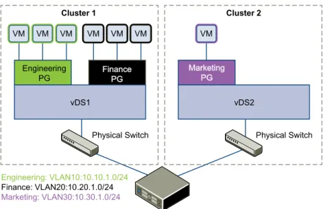
This scenario presents a situation where company ACME Enterprise has several ESX hosts on two clusters in a datacenter, ACME_Datacenter. The Engineering (on port group PG-Engineering) and Finance
departments (on port group PG-Finance) are on Cluster1. The Marketing department (PG-Marketing) is on Cluster2. Both clusters are managed by a single vCenter Server 5.5.
Figure 2‑1. ACME Enterprise network before implementing logical switches
Engineering
PG FinancePG
Physical Switch
Cluster 1
Engineering: VLAN10:10.10.1.0/24
Finance: VLAN20:10.20.1.0/24 Marketing: VLAN30:10.30.1.0/24
vDS1
VM VM VM
Physical Switch vDS2
VM
Marketing PG
Cluster 2
VM VM VM
ACME is running out of compute space on Cluster1 while Cluster2 is under-utilized. The ACME network supervisor asks John Admin (ACME's virtualization administrator) to figure out a way to extend the Engineering department to Cluster2 in a way that virtual machines belonging to Engineering on both clusters can communicate with each other. This would enable ACME to utilize the compute capacity of both clusters by stretching ACME's L2 layer.
If John Admin were to do this the traditional way, he would need to connect the separate VLANs in a special way so that the two clusters can be in the same L2 domain. This might require ACME to buy a new physical device to separate traffic, and lead to issues such as VLAN sprawl, network loops, and
administration and management overhead.
John Admin remembers seeing a logical network demo at VMworld, and decides to evaluate NSX. He concludes that building a logical switch across dvSwitch1 and dvSwitch2 will allow him to stretch ACME's L2 layer. Since John can leverage the NSX controller, he will not have to touch ACME's physical
Figure 2‑2. ACME Enterprise implements a logical switch
Engineering
PG FFiinnaanncceePPGG
Physical Switch
Cluster 1
vDS1
VM VM VM
Physical Switch vDS2
VM
M Maarrkkeettiinngg
P PGG
Cluster 2
Logical Switch stretches across multiple VLANs/subnets
VM VM VM
Engineering: VXLAN5000:10.10.1.0/24
Finance: VXLAN5001:10.20.1.0/24 Marketing: VXLAN5002:10.30.1.0/24
Engineering PG
VM VM VM
VM VM
Once John Admin builds a logical switch across the two clusters, he can vMotion virtual machines within the vDS.
Figure 2‑3. vMotion on a logical network
vMotion range vMotion range
Engineering
PG FFiinnaanncceePPGG
vDS1
VM VM VM
vDS2 VM
M Maarrkkeettiinngg
P PGG
VM VM VM
Engineering: VXLAN5000:10.10.1.0/24
Finance: VXLAN5001:10.20.1.0/24 Marketing: VXLAN5002:10.30.1.0/24
Engineering PG
VM VM VM
VM VM
John Admin Assigns Segment ID Pool and Multicast Address Range to NSX
Manager
John Admin must specify the segment ID pool he received to isolate Company ABC's network traffic.
Prerequisites
1 John Admin verifies that dvSwitch1 and dvSwitch2 are VMware distributed switches version 5.5. 2 John Admin sets the Managed IP address for the vCenter Server.
a Select Administration > vCenter Server Settings > Runtime Settings. b In vCenter Server Managed IP, type 10.115.198.165.
c Click OK.
3 John Admin installs the network virtualization components on Cluster1 and Cluster 2. See NSX
Installation and Upgrade Guide.
4 John Admin gets a segment ID pool (5000 - 5250) from ACME's NSX Manager administrator. Since he is leveraging the NSX controller, he does not require multicast in his physical network.
5 John Admin creates an IP pool so that he can assign a static IP address to the VXLAN VTEPs from this IP pool. See “Add an IP Pool,” on page 67.
Procedure
1 In the vSphere Web Client, click Networking & Security > Installation. 2 Click the Logical Network Preparation tab and then click Segment ID. 3 Click Edit.
4 In Segment ID pool, type 5000 - 5250.
5 Do not select Enable multicast addressing. 6 Click OK.
John Admin Configures VXLAN Transport Parameters
John Admin configures VXLAN on Cluster 1 and Cluster 2, where he maps each cluster to a vDS. When he maps a cluster to a switch, each host in that cluster is enabled for logical switches.
Procedure
1 Click the Host Preparation tab.
2 For Cluster1, select Configure in the VXLAN column.
3 In the Configuring VXLAN networking dialog box, select dvSwitch1 as the virtual distributed switch for the cluster.
4 Type 10 for dvSwitch1 to use as the ACME transport VLAN.
5 In Specify Transport Attributes, leave 1600 as the Maximum Transmission Units (MTU) for dvSwitch1. MTU is the maximum amount of data that can be transmitted in one packet before it is divided into smaller packets. John Admin knows that VXLAN logical switch traffic frames are slightly larger in size because of the encapsulation, so the MTU for each switch must be set to 1550 or higher.
7 For VMKNic Teaming Policy, select Failover.
John Admin wants to maintain the quality of service in his network by keeping the performance of logical switches the same in normal and fault conditions. Hence, he chooses Failover as the teaming policy.
8 Click Add.
9 Repeat steps 4 through step 8 to configure VXLAN on Cluster2.
After John admin maps Cluster1 and Cluster2 to the appropriate switch, the hosts on those clusters are prepared for logical switches:
1 A VXLAN kernel module and vmknic is added to each host in Cluster 1 and Cluster 2.
2 A special dvPortGroup is created on the vSwitch associated with the logical switch and the VMKNic is connected to it.
John Admin Adds a Transport Zone
The physical network backing a logical network is called a transport zone. A transport zone is the compute diameter spanned by a virtualized network.
Procedure
1 Click Logical Network Preparation and then click Transport Zones. 2 Click the New Transport Zone icon.
3 In Name, type ACME Zone.
4 In Description, type Zone containing ACME's clusters. 5 Select Cluster 1 and Cluster 2 to add to the transport zone. 6 In Control Plane Mode, select Unicast.
7 Click OK.
John Admin Creates a Logical Switch
After John Admin configures VXLAN transport parameters, he is ready to create a logical switch.
Procedure
1 Click Logical Switches and then click the New Logical Network icon. 2 In Name, type ACME logical network.
3 In Description, type Logical Network for extending ACME Engineering network to Cluster2.
4 In Transport Zone, select ACME Zone. 5 Click OK.
NSX creates a logical switch providing L2 connectivity between dvSwitch1 and dvSwitch2.
What to do next
John Admin can now connect ACME's production virtual machines to the logical switch, and connect the logical switch to an NSX Edge services gateway or Logical Router.
L2 Bridges
3
You can create an L2 bridge between a logical switch and a VLAN, which enables you to migrate virtual workloads to physical devices with no impact on IP addresses. A logical network can leverage a physical L3 gateway and access existing physical networks and security resources by bridging the logical switch broadcast domain to the VLAN broadcast domain.
The L2 bridge runs on the host that has the NSX Edge logical router virtual machine. An L2 bridge instance maps to a single VLAN, but there can be multiple bridge instances. The logical router cannot be used as a gateway for devices connected to a bridge.
If High Availability is enabled on the Logical Router and the primary NSX Edge virtual machine goes down, the bridge is automatically moved over to the host with the secondary virtual machine. For this seamless migration to happen, a VLAN must have been configured on the host that has the secondary NSX Edge virtual machine.
VXLAN 5001
Compute rack VM
Physical workload
Physical gateway
VLAN 100
NSX Edge logical router virtual machine
L2 bridge
Note that you should not use an L2 bridge to connect a logical switch to another logical switch, a VLAN network to another VLAN network, or to interconnect datacenters.
Add L2 Bridge
You can add a bridge from a logical switch to a distributed virtual port group.
Prerequisites
An NSX logical router must be deployed in your environment.
Procedure
1 Log in to the vSphere Web Client.
2 Click Networking & Security and then click NSX Edges. 3 Double-click an NSX Edge.
4 Click Manage and then click Bridging. 5 Click the Add icon.
6 Type a name for the bridge.
7 Select the logical switch that you want to create a bridge for.
8 Select the distributed virtual port group to which you want to bridge the logical switch. 9 Click OK.
Logical Router
4
You can specify static and dynamic routing for each NSX Edge.
Dynamic routing provides the necessary forwarding information between Layer 2 broadcast domains, thereby allowing you to decrease Layer 2 broadcast domains and improve network efficiency and scale. NSX extends this intelligence to where the workloads reside for doing East-West routing. This allows more direct virtual machine to virtual machine communication without the added cost or time needed to extend hops. At the same time, NSX also provides North-South connectivity, thereby enabling tenants to access public networks.
This chapter includes the following topics:
n “Specify Global Configuration,” on page 33 n “Add a Static Route,” on page 34
n “Configure OSPF,” on page 35 n “Configure BGP,” on page 36
n “Configure IS-IS Protocol,” on page 37 n “Configure Route Redistribution,” on page 38
Specify Global Configuration
You can configure the default gateway for static routes and specify dynamic routing details for an Edge Services Gateway or Distributed Router.
You must have a working NSX Edge instance before you can configure routing on it. For information on setting up NSX Edge, see “NSX Edge Operations,” on page 170.
Procedure
1 Log in to the vSphere Web Client.
2 Click Networking & Security and then click NSX Edges. 3 Double-click an NSX Edge.
4 Click Routing and then click Global Configuration.
5 To enable Equal-cost multi-path routing (ECMP), click Enable next to ECMP.
ECMP is a routing strategy that allows next-hop packet forwarding to a single destination can occur over multiple best paths. These best paths can be added statically or as a result of metric calculations by dynamic routing protocols like OSPF or BGP. Multiple paths for static routes can be added by
providing multiple next hops separated by commas in the Static Routes dialog box. For more information, see “Add a Static Route,” on page 34.
The Edge Services Gateway utilizes Linux network stack implementation, a roundrobin algorithm with a randomness component. After a next hop is selected for a particular source and destination IP address pair, the route cache stores the selected next hop. All packets for that flow go to the selected next hop. The default IPv4 route cache timeout is 300 seconds (gc_timeout). If an entry is inactive for this time, it is eligible to be removed from the route cache. The actual removal happens when garbage collection timer activates (gc_interval = 60 seconds).
The Logical Router uses an XOR algorithm to determine the next hop from a list of possible ECMP next hops. This algorithm uses the source and destination IP address on the outgoing packet as sources of entropy.
Enabling ECMP disables firewall on the Edge Services Gateway virtual machine. Stateful services such as NAT do not work with ECMP.
6 To specify the default gateway, click Edit next to Default Gateway.
a Select an interface from which the next hop towards the destination network can be reached. b Type the gateway IP if required.
c Edit the MTU if required and type a description. d Click Save.
7 To configure dynamic routing, click Edit next to Dynamic Routing Configuration.
a Router ID displays the first uplink IP address of the NSX Edge that pushes routes to the kernel for
dynamic routing.
b Do not enable any protocols here.
c Select Enable Logging to save logging information and select the log level.
NOTE If you have IPSec VPN configured in your environment, you should not use dynamic routing. 8 Click Publish Changes.
What to do next
To delete routing configuration, click Reset. This deletes all routing configurations (default, static, OSPF, and BGP configurations, as well as route redistribution).
Add a Static Route
You can add a static route for a destination subnet or host.
Procedure
1 Log in to the vSphere Web Client.
2 Click Networking & Security and then click NSX Edges. 3 Double-click an NSX Edge.
4 Click the Manage tab and then click the Routing tab. 5 Select Static Routes from the left panel.
6 Click the Add ( ) icon.
7 Type a description for the static route.
8 Select the interface on which you want to add a static route. 9 Type the Network in CIDR notation.
10 Type the IP address of the Next Hop.
The router must be able to directly reach the next hop. If ECMP is enabled, you can type multiple next hops.
11 For MTU, edit the maximum transmission value for the data packets if required. The MTU cannot be higher than the MTU set on the NSX Edge interface. 12 Click OK.
Configure OSPF
NSX Edge supports OSPF, an interior gateway protocol that routes IP packets only within a single routing domain. It gathers link state information from available routers and constructs a topology map of the network. The topology determines the routing table presented to the Internet Layer, which makes routing decisions based on the destination IP address found in IP packets.
OSPF routing policies provide a dynamic process of traffic load balancing between routes of equal cost. An OSPF network is divided into routing areas to optimize traffic flow and limit the size of routing tables. An area is a logical collection of OSPF networks, routers, and links that have the same area identification. Areas are identified by an Area ID.
Prerequisites
Router ID must have been specified. See “Specify Global Configuration,” on page 33.
Procedure
1 Log in to the vSphere Web Client.
2 Click Networking & Security and then click NSX Edges. 3 Double-click an NSX Edge.
4 Click Routing and then click OSPF. 5 Do one of the following.
Option Description
For an Edge services gateway a Click Edit at the top right corner of the window. b Click Enable OSPF.
c Click Enable Graceful Restart for packet forwarding to be un-interrupted during restart of OSPF services.
d Click Enable Default Originate to allow NSX Edge to advertise itself as a default gateway to its peers.
e Click OK.
For a logical router a Click Edit at the top right corner of the window.
b Click Enable OSPF.
c In Forwarding Address, type an IP address that is to be used by the router datapath module in the hosts to forward datapath packets. d In Protocol Address, type a unique IP address within the same subnet
as the Forwarding Address. Protocol address is used by the protocol to form adjacencies with the peers.
6 In Area Definitions, click the Add icon.
8 In Type, select Normal or NSSA.
Not so stubby areas (NSSA) prevent the flooding of AS-external link-state advertisements (LSAs) into NSSAs. They rely on default routing to external destinations. Hence, NSSAs must be placed at the edge of an OSPF routing domain. NSSAs are more flexible as NSSA can import external routes into the OSPF routing domain, thereby providing transit service to small routing domains that are not part of the OSPF routing domain.
9 Select the type of Authentication. OSPF performs authentication at the area level. Hence, all routers within the area must have the same authentication and corresponding password configured. For MD5 authentication to work, both the receiving and transmitting routers must have the same MD5 key. a None: No authentication is required, which is the default value.
b Password: In this method of authentication, a password is included in the transmitted packet.
c MD5: This authentication method uses MD5 (Message Digest type 5 ) encryption. An MD5
checksum is included in the transmitted packet.
10 For Password or MD5 type authentication, type the password or MD5 key. 11 Click OK.
12 In Area to Interface Mapping, click the Add icon to map the interface that belongs to the OSPF area. 13 Select the interface that you want to map and the OSPF area that you want to map it to.
14 Hello Interval displays the default interval between hello packets that are sent on the interface. Edit the default value if required.
15 Dead Interval displays the default interval during which at least one hello packet must be received from a neighbor before the router declares that neighbor down. Edit the default interval if required. 16 Priority displays the default priority of the interface. The interface with the highest priority is the
designated router. Edit the default value if required.
17 Cost of an interface displays the default overhead required to send packets across that interface. The cost of an interface is inversely proportional to the bandwidth of that interface. The larger the bandwidth, the smaller the cost. Edit the default value if required.
18 Click OK and then click Publish Changes.
Configure BGP
Border Gateway Protocol (BGP) makes core routing decisions. It includes a table of IP networks or prefixes, which designate network reachability among multiple autonomous systems.
An underlying connection between two BGP speakers is established before any routing information is exchanged. Keepalive messages are sent by the BGP speakers in order to keep this relationship alive. After the connection is established, the BGP speakers exchange routes and synchronize their tables.
Procedure
1 Log in to the vSphere Web Client.
2 Click Networking & Security and then click NSX Edges. 3 Double-click an NSX Edge.
4 Click Routing and then click BGP. 5 Click Edit.
7 Click Enable Graceful Restart for packet forwarding to be un-interrupted during restart of BGP services.
8 Click Enable Default Originate to allow NSX Edge to advertise itself as a default gateway to its peers. 9 Type the router ID in Local AS. Type the Local AS. This is advertised when BGP peers with routers in
other autonomous systems (AS). The path of ASs that a route traverses is used as one metric when selecting the best path to a destination.
10 Click OK.
11 In Neighbors, click the Add icon. 12 Type the IP address of the neighbor. 13 Type the remote AS.
14 Edit the default weight for the neighbor connection if required.
15 Hold Down Timer displays interval (180 seconds) after not receiving a keep alive message that the software declares a peer dead. Edit if required.
16 Keep Alive Timer displays the default frequency (60 seconds) with which the software sends keepalive messages to its peer. Edit if required.
17 If authentication is required, type the authentication password. Each segment sent on the connection between the neighbors is verified. MD5 authentication must be configured with the same password on both BGP neighbors, otherwise, the connection between them will not be made.
18 To specify route filtering from a neighbor, click the Add icon in the BGP Filters area.
CAUTION A "block all" rule is enforced at the end of the filters.
19 Select the direction to indicate whether you are filtering traffic to or from the neighbor. 20 Select the action to indicate whether you are allowing or denying traffic.
21 Type the network in CIDR format that you want to filter to or from the neighbor. 22 Type the IP prefixes that are to be filtered and click OK.
23 Click Publish Changes.
Configure IS-IS Protocol
Intermediate System to Intermediate System (IS-IS) is a routing protocol designed to move information by determining the best route for datagrams through a packet-switched network.
A two-level hierarchy is used to support large routing domains. A large domain may be divided into areas. Routing within an area is referred to as Level 1 routing. Routing between areas is referred to as Level 2 routing. A Level 2 Intermediate System (IS) keeps track of the paths to destination areas. A Level 1 IS keeps track of the routing within its own area. For a packet going to another area, a Level 1 IS sends the packet to the nearest Level 2 IS in its own area, regardless of what the destination area is. Then the packet travels via Level 2 routing to the destination area, where it may travel via Level 1 routing to the destination. An IS in both Level 1 and Level 2 is referred to as Level-1-2.
NOTE NSX support for the IS-IS protocol is currently experimental.
Procedure
1 Log in to the vSphere Web Client.
3 Double-click an NSX Edge. 4 Click Routing and then click IS-IS. 5 Click Edit and then click Enable IS-IS. 6 Type the System ID and select the IS-IS type.
Level 1 is intra-area, Level 2 is inter-area, and Level 1-2 is both. Level 2 routers are inter-area routers that can only form relationships with other Level 2 routers. Routing information is exchanged between Level 1 routers and other Level 1 routers. Likewise Level 2 routers only exchange information with other Level 2 routers. Level 1-2 routers exchange information with both levels and are used to connect the inter-area routers with the intra-area routers.
7 Type the Domain Password and Area Password. The area password is inserted and checked for Level 1 link state packets, and the domain password for Level 2 link state packets.
8 Define the IS-IS areas.
a Click the Add icon in Areas. b Type up to three area IP addresses. c Click Save.
9 Configure interface mapping.
a Click the Add icon in Interface Mapping.
b Choose the Circuit Type to indicate whether you are configuring the interface for Level-1, Level-2, or Level-1-2 adjacency.
c Hello Interval displays the default interval in milliseconds between hello packets that are sent on
the interface. Edit the default value if required.
d Hello Multiplier displays the default number of IS-IS hello packets a neighbor must miss before it
is declared down. Edit the default value if required.
e LSP Interval displays the time delay in milliseconds between successive IS-IS link-state packet
(LSP) transmissions. Edit the default value if required.
f Metric displays the default metric for the interface. This is used to calculate the cost from each
interface via the links in the network to other destinations. Edit the default value if required. g Priority displays the priority of the interface. The interface with the highest priority becomes the
designated router. Edit the default value if required.
h In Mesh Group, type the number identifying the mesh group to which this interface belongs. Edit the default value if required.
i Type the authentication password for the interface and click OK. Edit the default value if required. 10 Click Publish Changes.
Configure Route Redistribution
By default, routers share routes with other routers running the same protocol. In a multi-protocol environment, you must configure route redistribution for cross-protocol route sharing.
Procedure
1 Log in to the vSphere Web Client.
2 Click Networking & Security and then click NSX Edges. 3 Double-click an NSX Edge.
4 Click Routing and then click Route Redistribution. 5 Click Change next to Route Redistribution Status.
6 Select the protocols for which you enable route redistribution and click OK. 7 Add an IP prefix.
Entries in the IP Prefix list are processed sequentially. a Click the Add icon in IP Prefixes.
b Type a name and IP address of the network. c Click OK.
8 Specify redistribution criteria for the IP prefix. a Click the Add icon in Route Redistribution table.
b In Learner Protocol, select the protocol that is to learn routes from other protocols. c In Allow Learning from, select the protocols from which routes should be learned. d Click OK.
Logical Firewall
5
Logical Firewall provides security mechanisms for dynamic virtual data centers, and consists of two components to address different deployment use cases. Distributed Firewall focuses on East-West access controls, and Edge Firewall focuses on the North-South traffic enforcement at the tenant or datacenter perimeter. Together, these components address the end-to-end firewall needs of virtual datacenters. You can choose to deploy either of these technologies independently, or deploy both of them.
This chapter includes the following topics:
n “Distributed Firewall,” on page 41 n “Edge Firewall,” on page 42
n “Working with Firewall Rules,” on page 42 n “Working with Firewall Rule Sections,” on page 50 n “Working with Firewall Configurations,” on page 51
n “Excluding Virtual Machines from Firewall Protection,” on page 52 n “Using SpoofGuard,” on page 53
n “View Firewall CPU and Memory Threshold Events,” on page 56 n “Firewall Logs,” on page 56
n “Working with Local Rules,” on page 56
Distributed Firewall
Distributed Firewall is a hypervisor kernel-embedded firewall that provides visibility and control for virtualized workloads and networks. You can create access control policies based on VMware vCenter objects like datacenters and clusters and virtual machine names; network constructs like IP or IPSet addresses, VLAN (DVS port-groups), VXLAN (logical switches), security groups, as well as user group identity from Active Directory. Firewall rules are enforced at the vNIC level of each virtual machine to provide consistent access control even when the virtual machine gets vMotioned. The hypervisor-embedded nature of the firewall delivers close to line rate throughput to enable higher workload consolidation on physical servers. The distributed nature of the firewall provides a scale-out architecture that automatically extends firewall capacity when additional hosts are added to a datacenter.
For L2 packets, Distributed Firewall creates a cache for performance boost. L3 packets are processed in the following sequence:
1 All packets are checked for an existing state. This is done for SYNs too so that bogus or retransmitted SYNs for existing sessions can be detected.