ISSN (Online): 2347-3878, Impact Factor (2014): 3.05
Position Control and Anti-Swing Control of
Overhead Crane Using LQR
Liji Ramesan Santhi
1, Laila Beebi M
21
Department of Electrical and Electronics Engineering, TKM College of Engineering, Kollam
2
Professor, Department of Electrical and Electronics Engineering, TKM College of Engineering, Kollam
Abstract: A crane is a machine equipped with a hoist, wire ropes or chains which is mainly used both to lift and lower materials and move them horizontally to different places. It is mainly used for lifting things of huge mass and transporting them to different locations.
Overhead crane is widely used to convey the payload due to its convenience. However the underactuated structure of the crane makes difficult to control. The most important control requirement is to make the trolley position converge to desired position accurately with less payload swing which otherwise hinders the precise positioning of the load. This makes it possible to achieve the purpose of overhead crane which is mainly used to convey payload to the desired position in a stable manner. In the practical situations, however, the achievement of both transporting trolley to target position and reducing payload sway is not always easy. To achieve a good control performance of overhead crane, sensors are indispensable instrument which are used for feedback signals. However, sensing the payload motion of the crane, particularly swing motion, is a difficult task and also expensive. Therefore, a crane system with no swing angle sensor is developed and considered in this paper. A soft sensor based on the mathematical model of the crane is introduced to substitute the real sensor is used earlier. In the proposed method, the motion of the payload is estimated based on the mathematical model of the crane and the measured trolley position. The proposed soft sensor based anti-swing control strategy is effective for reducing the payload swing and it gives similar performance to the sensor based anti-swing control strategy. The objective is to employ a linear quadratic regulator for controlling the trolley position and swing motion which give better performance than simple PD and PID control. Moreover, the proposed method has robustness to deal with parameter variations.
Keywords:Overhead crane, Linear Quadratic Regulator (LQR), State Variables, Performance Index
1.
Introduction
The main purpose of controlling an overhead crane is transporting the load as fast as possible without causing any excessive swing from one position to another. However, most of the common overhead crane results in a swing movement when payload is suddenly stopped after a fast motion [1]. The overhead crane are used mainly in the industries, hazardous environments like nuclear power plant due to its low cost, easy assembly, precise positioning of load and less maintenance. The swing motion can be reduced by adjusting the speed of the motor but it will be time-consuming process. Moreover, a crane needs a skilful operator to control both the position and swing manually based on his or her experiences to stop the swing immediately at the desired position. The inefficiency of controlling crane also might cause accident and create harm to the people and the surroundings.
Various attempts in controlling cranes system based on open loop system were proposed. Earlier open loop time optimal strategies were applied to the overhead crane by many researchers such as discussed in [2],[3]. They came out with poor results because open loop strategy is sensitive to the system parameters (e.g. rope length) and could not compensate for wind disturbances. Another importance of open loop strategy is the input shaping introduced by Karnopp [4], Teo [5] and Singhose [6]. However the input shaping method is still an open-loop approach. Hubbel et al. [7] used an open-loop method to control the motion of the crane. In this open loop control method, the input control profile was determined in such a way that unwanted oscillations and residual pendulations were eliminated. However their approach was applicable, but the open loop control scheme is not robust to disturbances and parameter
uncertainties [8]. Moreover, a feedback PID anti-swing controller is developed in [9] to control of an overhead crane. Ahmad et al. [10] used a hybrid input-shaping method to control of the crane. Wahyudi and Jalani [11] introduced fuzzy logic feedback controller to control the intelligent crane. They also presented an optimal control method is used in [12] to control the dynamic motion of the crane. Here, minimum energy of the system and also integrated absolute error of payload angle are assumed as their optimization criterion. Zhao and Gao [13] studied the control of the overhead crane. They proposed a fuzzy control method to control the input delay and actuator saturation of the system. Nazemizadeh et al. [14] studied tracking control of the crane. Furthermore, Nazemizadeh [15] presented a PID tuning method for tracking control of a crane.
In this paper, overhead crane is provided with a linear quadratic regulator to control both swing and position of the crane and the results are compared with PD and PID control. The structure of this paper is as follows. Section 2 describes about the basic concept of soft sensor. The modelling of the crane is explained in section 3. Section 4 highlights the development of model-based soft sensor. Section 5 discuses about the crane with conventional PD and PID controller. Section 6 discusses about the crane with linear quadratic regulator. Simulation results is given in section 7. Conclusion and future scope is discussed in section 8 and 9 respectively.
2.
Basic Concept of Soft Sensor
Most of the feedback control system proposed till now needs sensors for measuring the trolley position as well as the load swing angle. In addition, designing of the swing angle measurement of the crane, in particular, is not an easy task
www.ijser.in
ISSN (Online): 2347-3878, Impact Factor (2014): 3.05
since there is a need for hoisting the system. Some researchers have also focused on some control techniques with vision system that is more feasible because the vision sensor is not located at the load side. The drawbacks of the vision system are mainly difficult to maintain and its high cost [16]. To avoid this problem, a sensorless anti-swing control strategy based on soft sensor is proposed and developed for the overhead crane. The proposed soft sensor is mainly based on the mathematical model of the crane such that it produces output estimation signal required for feedback control. Hence the real sensor which is used for measuring load swing angle is physically omitted and is replaced by the proposed soft sensor.
To realize a reliable control of system with dynamic nature, an accurate states of measurement is important. However, such accurate measurement may not be obtained due to some reasons. Sensors are unable to be installed because it may be expensive. In some cases, due to the device technology limitations the states of interest cannot be obtained or the measurement may be inaccurate. Hence, an inferential measurement by a soft sensor is a breakthrough. A soft sensor or virtual sensor is basically a system model designed to replace the momentary or permanent unavailability of a real sensor in the object to be controlled [17]. In the case of no available sensor, a soft sensor may be designed using sampling and off-line laboratory analysis. It is a modeling approach to obtain difficult-to-measure variables from easy-to-measure variables [18]. The recent applications are mostly in industrial plants or process where highly nonlinear and uncertainties occur. The problem of designing a soft sensor can be considered as model identification or parameter estimation to the system. It may involve mathematical modeling technique, intelligent control techniques such as neural network and fuzzy or others.
3.
Modelling of the Crane
As model-based soft sensor is adopted in the proposed method, therefore, the crane model is required to develop the model-based soft sensor. Fig. 1 shows a schematic diagram of the crane considered in this paper. Due to the fact that only planar motion of crane is considered in this paper, there are two independent coordinates namely yand to describe the trolley position and the swing angle of the payload respectively.
Since the mass of the rope is small enough as compared to the payload mass . The non-linear dynamic model of overhead crane prototype is derived using Lagrange equations.
(2) By assuming small motion of the following linearized model of the crane is obtained.
= (3) (4) In the above equation, mt is the mass of the trolley, mp mass
of the payload, l is the length of the rope, y is the position of the trolley, is the swing angle and 𝜃 is the force F provided
by the dc motor. Thus the state space model of the overhead crane can be obtained as
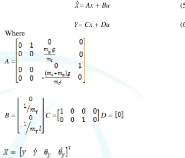
= Ax + Bu (5)
Y= Cx + Du (6) Where
A =
B = C = D =
The translational motion of trolley is driven by DC motor. Therefore, to obtain the entire model of the crane, the motor dynamic is modeled according to equivalent DC motor circuit. The equivalent circuit of DC motor has armature resistance R, inductance L, motor inertia J, torque constant , input voltage to the dc motor V, armature current I and damping coefficient B.The rotational motion is converted to translational motion through the mechanical part (pulley or gear) with radii of r. The trolley is driven by dc motor. The dynamics of dc motor circuit is
V = RI+L + (7)
T = I (8)
J + B = T (9)
Figure 1: Crane Model
4.
Development of Model Based Soft Sensor
Most of the overhead crane use two controllers for controlling both trolley position and swing of the crane payload. Therefore two sensors are needed to measure the trolley position Y(s) and swing angle (s). The latter is usually installed on the load side.
Since the use of sensors on the load side is troublesome, a model-based soft sensor is proposed to provide output estimation of the plant. The dynamic information from trolley position Y(s) is given to the developed soft sensor. It produces output estimation of the payload motion that will be used for feedback signal to the controller.
ISSN (Online): 2347-3878, Impact Factor (2014): 3.05
As model-based soft sensor is adopted in the proposed method, therefore, crane model discussed in the previous section as used to develop the model-based soft sensor. The proposed model based soft sensor is used to estimate the swing angle of the payload based on the position of the trolley. Consequently, dynamic model is used as model-based soft sensor. According to the equations, the swing angle of payload is estimated by using the following:
=
(10) Where and Y(s) are estimated swing motion of the payload and trolley motion in Laplace domain respectively. It is shown that the proposed model-based soft sensor is easily and practically implemented since it has a simple structure and depends only on the length of the rope l and gravity which are easily known.5.
Crane with Conventional PID and PD
Controller
Well known classical PID controllers are designed and used to evaluate the effectiveness of the proposed model-based soft sensor. The function of the controller is to control the payload position Y(s) so that it moves to the desired position as fast as possible without excessive swing angle . A PID controller is adopted to control the trolley position, while a PD controller is used for swing control. The controller gains for PID are designed and optimized with simulation model by using Simulink response optimization library block. It is mainly a numerical time domain optimizer developed under MATLAB/Simulink environment. Hence the response obtained by the simulink optimization library block assists in time-domain-based control design by setting the desired overshoot, settling time and steady state error. Inorder to realize fast motion with small overshoot, the PID controller is optimized. Moreover, in order to suppress the swing angle quickly, the PD controller is optimized. Thus there are five parameters to be optimized in order to have satisfactory control performance. Those are corresponding respectively to Kp, Ki, Kd, Kps and Kds which are the proportional, integral and derivative gains for the position control and proportional, derivative gains for the anti-swing control. The optimization to obtain PID+PD gains for anti-swing crane control was done using genetic algorithm-based optimization [19]. Based on the result in [19], the gains of Kp, Ki, Kd, Kps and Kds are shown in Table 2.
Table 2: Optimized PID+PD position and anti-swing gains
Kp Ki Kd Kps Kds
140.4 0.7 136.5 43.5 12.8
6.
Linear Quadratic Regulator (LQR)
The stability is a major problem in an overhead crane system. The design of a state feedback crane control is based on a suitable selection of a feedback system structure. If the state variables are known, then they can be utilized to design a feedback controller so that the input becomes u = Kx. It is
necessary to measure and utilize the state variables of the system in order to control the position and swing angle of the crane. This design approach of state variable feedback control gives sufficient information about the stability of the crane. The design of a feedback control system for the crane using state variables are discussed in this section. Let us choose a feedback control system so that,
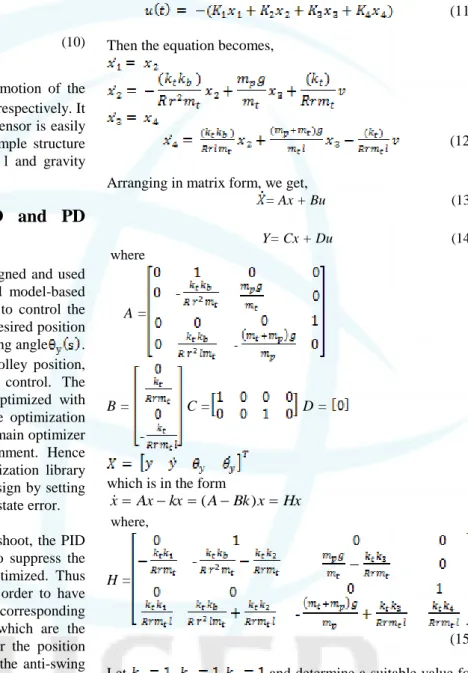
(11) Then the equation becomes,
(12) Arranging in matrix form, we get,
= Ax + Bu (13)
Y= Cx + Du (14) where
A =
B = C = D =
which is in the form
Hx x Bk A kx Ax x ( ) where, H = (15) Let , and determine a suitable value for so that the performance index is minimized. To minimize the performance index J, consider the following two equations, 0 ) 0 ( ) 0 ( PX T X Xdt T X J (16) I PH P T H (17) To minimize as a function of Set 0 4 k J
Therefore and is obtained.
The system matrix H obtained for the compensated system and the feedback control signal is obtained as
www.ijser.in
ISSN (Online): 2347-3878, Impact Factor (2014): 3.05 4 8037 . 7 3 2263 . 31 2 4966 . 13 1 10x x x x u (18) This compensated system is considered to an optimal system which results in a minimum value for the performance index. The simulation of this compensated system is done in the next section.
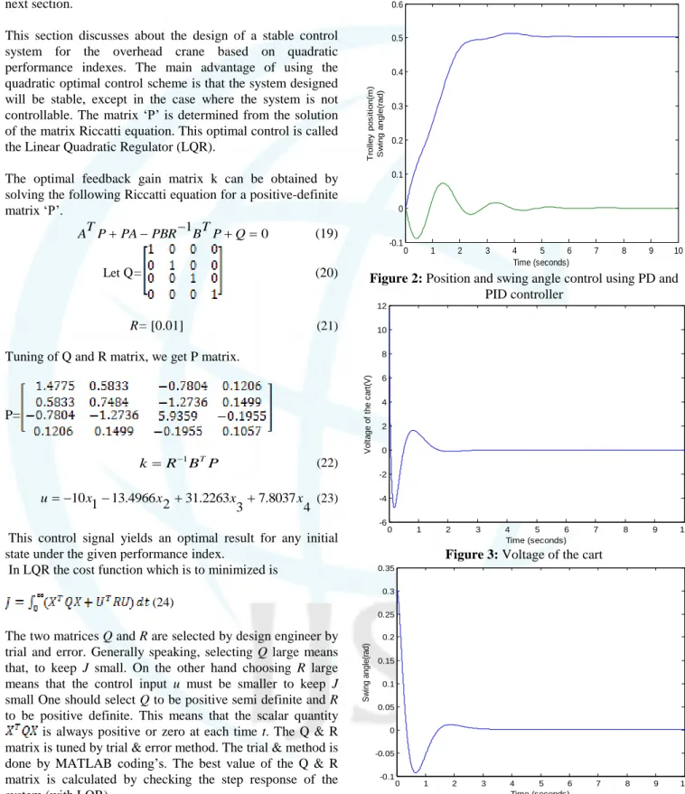
This section discusses about the design of a stable control system for the overhead crane based on quadratic performance indexes. The main advantage of using the quadratic optimal control scheme is that the system designed will be stable, except in the case where the system is not controllable. The matrix „P‟ is determined from the solution of the matrix Riccatti equation. This optimal control is called the Linear Quadratic Regulator (LQR).
The optimal feedback gain matrix k can be obtained by solving the following Riccatti equation for a positive-definite matrix „P‟. 0 1 PA PBR BTP Q P T A (19) Let Q= (20) R= [0.01] (21) Tuning of Q and R matrix, we get P matrix.
P= P B R k 1 T (22) 4 8037 . 7 3 2263 . 31 2 4966 . 13 1 10x x x x u (23)
This control signal yields an optimal result for any initial state under the given performance index.
In LQR the cost function which is to minimized is (24)
The two matrices Q and R are selected by design engineer by trial and error. Generally speaking, selecting Q large means that, to keep J small. On the other hand choosing R large means that the control input u must be smaller to keep J
small One should select Q to be positive semi definiteand R
to be positive definite. This means that the scalar quantity is always positive or zero at each time t. The Q & R matrix is tuned by trial & error method. The trial & method is done by MATLAB coding‟s. The best value of the Q & R matrix is calculated by checking the step response of the system (with LQR).
7.
Simulation Results
MATLAB software package is used to determine the response of the system. The Simulink model of the system with optimized values of PD and PID controller is created in
MATLAB. Tuning of the Q & R matrix is done by separate coding. The regulation of position and swing angle is determined with tuning of Q & R matrix and the tracking of the crane also determined. The Simulink model of the system is developed. 0 1 2 3 4 5 6 7 8 9 10 -0.1 0 0.1 0.2 0.3 0.4 0.5 0.6 Time (seconds) T ro ll e y p o s it io n (m ) S w in g a n g le (r a d )
Time Series Plot:
Figure 2: Position and swing angle control using PD and PID controller 0 1 2 3 4 5 6 7 8 9 10 -6 -4 -2 0 2 4 6 8 10 12 Time (seconds) V o lt a g e o f th e c a rt (V )
Time Series Plot:
Figure 3: Voltage of the cart
0 1 2 3 4 5 6 7 8 9 10 -0.1 -0.05 0 0.05 0.1 0.15 0.2 0.25 0.3 0.35 Time (seconds) S w in g a n g le (r a d )
Time Series Plot:
ISSN (Online): 2347-3878, Impact Factor (2014): 3.05 0 1 2 3 4 5 6 7 8 9 10 -0.14 -0.12 -0.1 -0.08 -0.06 -0.04 -0.02 0 0.02 0.04 Time (seconds) P o s it io n o f th e c a rt (m )
Time Series Plot:
Figure 5: Position of the cart
The figure 2 shows the position and swing angle control using optimized values for Kp, Ki, Kd, Kps and Kds which are the proportional, integral and derivative gains for position control and proportional, derivative gains for anti-swing control. From figure 3, figure 4 and figure 5, the system is regulated at 2 sec, 3 sec and 5 sec respectively and the system consists of small no of overshoot and undershoot when compared to PD and PID controller. The system is precisely regulated at this condition.
8.
Conclusion
In this paper a state variable feedback system was designed for the overhead crane to achieve the desired system response. Also, an LQR system was designed for the crane which results in a minimum value for the performance index. This optimal controlled system results in a minimum value for the performance index. Also, the control law given by equation (18) yields optimal result for any initial state under the given performance index. Both the transient and steady state response of the system is improved with LQR controller. This design based on the quadratic performance index yields a stable control system for the overhead crane.
9.
Future Scope
From the foregoing analysis, disturbance is not introduced into the system. A tuned Linear Quadratic Gaussian controller eliminates the disturbance affect into the system. A noise signal is added in the system and compare the response of the with tuned LQR controller.
References
[1] H.M, “Control of gantry and tower cranes”. Ph.D. Thesis, M.S.Virginia Tech, 2003.
[2] Manson, G.A., “Time-optimal control of and overhead crane model”, Optimal Control Applications & Methods, Vol. 3, No. 2, 1992, pp. 115-120.
[3] Auernig, J. and Troger, H. “Time optimal control of overhead cranes with hoisting of the load”, Autornatica, Vol. 23, 1987, pp. 437-447.
[4] Karnopp, B H., Fisher, F.E., and Yoon, B.O., "A strategy for moving mass from one point to another", Journal of the Franklin Institute, Vol. 329, 1992, pp. 881-892.
[5] Teo, C.L., Ong, C. J. and Xu, M. “Pulse input sequences for residual vibration reduction”. Journal of Sound and Vibration, Vol. 211, No. 2, 998, pp. 157-177.
[6] Singhose, W.E., Porter L.J. and Seering, W., "Input shaped of a planar gantry crane with hoisting", Proc. of the American Control Conference, 1997, pp. 97-100.
[7] Hubbell, J.T., Koch, B. and McCormick, D. 1992. “Modern crane control enhancements”. ASCE, USA: Seattle
[8] Masoud, Z.N. 2009. “Effect of hoisting cable elasticity on anti-sway controllers of quay-side container cranes.” Journal of Nonlinear Dynamics, 58: 129-140.
[9] Solihin, M.I., & Legowo, A. (2010). “Fuzzy-tuned PID anti-swing control of automatic gantry crane.” Journal of Vibration and Control, 16(1), 127-145.
[10]Ahmad, M. A., & Mohamed, Z. (2009). “Hybrid fuzzy logic control with input shaping for input tracking and sway suppression of a gantry crane system.” American Journal of Engineering and Applied Sciences, 2(1), 241. [11]Wahyudi, M. and Jalani, J. 2005. “Design and
implementation of fuzzy logic controller for an intelligent gantry crane system.” Proceedings of International Conference on Mechatronics, pp. 345- 351.
[12]Wang, Z. and Surgenor, B. 2004. “Performance evaluation of the optimal control of a gantry crane.” ASME Conference on Engineering Systems Design and Analysis, pp. 869-874.
[13]Zhao, Y., & Gao, H. (2012). “Fuzzy-model-based control of an overhead crane with input delay and actuator saturation.” Fuzzy Systems, IEEE Transactions on, 20(1), 181-186.
[14]Bakhtiari-Nejad F., Nazemizadeh M., and Arjmand H. (2013). “Tracking control of an underactuated gantry crane using an optimal feedback controller.” International Journal of Automotive & Mechanical Engineering, 7, 830- 839. [15]Nazemizadeh, M. (2013). “A PID Tuning Method for
Tracking Control of an Underactuated Gantry Crane.” Universal Journal of Engineering Mechanics, 1, 45-49. [16]Kim, Y.S., Yoshihara, H., Fujioka, N., Kasahara, H., Shim.
H., Sul, S.K.,“A new vision-sensorless anti-sway control system for container cranes”, Industry Applications Conference, 2003.
[17]Gonzalez, G.D., Redard, I.P., Barrera, R., Fernandez, M., "Issues in softsensor applications in industrial plants". Proc. of the IEEE International Symposium on Industrial Electronics, 1994, pp. 380-385.
[18]Jianxu, L., and Huihe, S. “Soft sensing modeling using neurofuzzysystem based on rough set theory”, Proceedings of the American Control Conference, 2002.
[19]Solihin M.I. and Wahyudi. “GA-based PID Controller Design for Automatic Gantry Crane System.” Proceedings of the International Conference on Intelligent Unmanned System (ICIUS), 2007.
Author Profile
Liji Ramesan Santhi was born in Kerala, India in 14/08/1990. She received B.Tech degree in Electrical and Electronics Engineering from Mohandas College of Engineering and Technology, Thiruvananthapuram, Kerala in 2012. Currently, she is pursuing his M Tech degree in Industrial Instrumentation & Control from TKM College of Engineering, Karicode, Kollam. Her research interests include Control Systems.