Part No. N0027269 01 08 April 2005
BCM50 IP Telephone
Installation and
Copyright © Nortel Networks Limited 2005
All rights reserved.The information in this document is subject to change without notice. The statements, configurations, technical data, and recommendations in this document are believed to be accurate and reliable, but are presented without express or implied warranty. Users must take full responsibility for their applications of any products specified in this document. The information in this document is proprietary to Nortel Networks.
Trademarks
*Nortel, Nortel (Logo), the Globemark, and This is the way, This is Nortel (Design mark) are trademarks of Nortel Networks. *Microsoft, MS, MS-DOS, Windows, and Windows NT are registered trademarks of Microsoft Corporation.
3
Task List
Registering Nortel 20XX IP telephones . . . 43
To access the local configuration menu on a 200X IP telephone...45
To troubleshoot IP telephones...47
To troubleshoot operation issues ...48
To deregister a 20XX IP telephone from the IP record...49
Global IP features . . . 51
To assign the services list to a button ...53
To use the Services button to access features...53
To define a key label ...54
To set up a password and allow Hot Desking ...56
To reset the Hot Desking password ...57
To use Hot Desking to divert an IP telephone configuration ...57
To cancel Hot Desking ...58
To configure a new time zone on a remote IP telephone ...58
To force a firmware download to a telephone ...59
Relocating telephones . . . 61
To keep an IP telephone active after it is disconnected ...61
To move an IP telephone without changing the DN ...61
5
Contents
Getting started . . . 7
About this guide . . . 7
Purpose . . . 7 Audience . . . 7 Organization . . . 7 About IP telephones . . . 8 About BCM50 . . . 8 BCM50 key elements . . . 8 BCM50 main units . . . 8 BCM50 hardware . . . 8 BCM50 features . . . 9 BCM50 applications . . . 9
Symbols and conventions used in this guide . . . 10
Related publications . . . 11
BCM50 Core Guides . . . 11
CallPilot and Call Center Guides . . . 12
How to get help . . . 14
USA and Canada Authorized Distributors . . . 14
Technical Support - GNTS/GNPS . . . 14
Presales Support (CSAN) . . . 14
EMEA (Europe, Middle East, Africa) . . . 14
Technical Support - CTAS . . . 14
CALA (Caribbean and Latin America) . . . 15
Technical Support - CTAS . . . 15
APAC (Asia Pacific) . . . 15
Technical Support - GNTS . . . 15
IP telephone overview . . . 17
IP telephones and VoIP trunks . . . 17
IP telephones . . . 17
VoIP trunks . . . 17
Creating the IP telephony network . . . 18
Networking with BCM50 . . . 19
M1-IPT . . . 20
Telephones . . . 20
Gatekeepers on the network . . . 20
IP network . . . 20
WAN . . . 21
Public Switched Telephone Network . . . 21
Key IP telephony concepts . . . 21
Codecs . . . 22
Jitter Buffer . . . 22
Configuring IP telephones . . . 25
Prerequisite programming . . . 25
IP telephone DN record overview . . . 26
Configuring an IP telephone . . . 27
DN records parameters . . . 29
Main panel tabs: common fields . . . 30
Line Access tab . . . 31
Line Access - Line Assignment tab . . . 32
Line Access - Answer DNs tab . . . 34
Capabilities and Preferences main tab . . . 35
Capabilities and Preferences - Capabilities tab . . . 37
Capabilities and Preferences - Preferences tab . . . 39
Capabilities and Preferences - IP Terminal Details tab . . . 41
Registering Nortel 20XX IP telephones . . . 43
Determining the registration process . . . 43
To register an IP Phone 20XX . . . 43
Registering the telephone to the system . . . 44
Configuring telephone settings . . . 44
Deregistering 20XX IP telephones . . . 48
Global IP features. . . 51
IP features list . . . 51
IP telephone feature display labels . . . 53
Hot Desking IP telephone configurations . . . 55
Notes about Hot Desking . . . 55
Using the Hot Desking feature . . . 56
Resetting the Hot Desking password . . . 57
Configuring a new time zone on a remote IP telephone . . . 58
Download firmware to a Nortel 20XX IP telephone . . . 59
Relocating telephones. . . 61
Keeping an IP telephone active . . . 61
Moving IP telephones . . . 61
7
Chapter 1
Getting started
This section contains information on the following topics:
• “About this guide”
• “About IP telephones” on page 8
• “About BCM50” on page 8
• “Symbols and conventions used in this guide” on page 10
• “Related publications” on page 11
• “How to get help” on page 14
About this guide
The BCM50 IP Telephone Installation and Configuration Guide describes how to install and configure Nortel IP telephones.
Purpose
The concepts, operations, and tasks described in the guide relate to the installation and
configuration of Nortel IP telephones, including the 2001, 2002, and 2004, for the BCM50 system. In brief, the information in this guide explains how to:
• Configure IP telephones
• Configure DN records parameters • Registering Nortel IP telephones
Audience
The BCM50 IP Telephone Installation and Configuration Guide is directed to installers responsible for installing and configuring BCM50 systems. To use this guide, you must:
• be an authorized BCM50 installer within your organization • know basic Nortel BCM50 terminology
• be knowledgeable about telephony and IP networking technology
Organization
This guide is organized for easy access to information that explains the concepts, operations, and procedures associated with the BCM50 system.
About IP telephones
This document provides instructions on installing and configuring IP telephones.
About BCM50
The Business Communications Manager 50 (BCM50) system provides private network and telephony management capability to small- and medium-sized businesses.
The BCM50 system:
• integrates voice and data capabilities, IP Telephony gateway functions, and data-routing features into a single telephony system
• enables you to create and provide telephony applications for use in a business environment
BCM50 key elements
BCM50 includes the following key elements:
BCM50 main units
Three types of main units are available: • BCM50 (with Telephony Only)
The BCM50 main unit provides call processing and simple data networking functions. It also provides connections for telephones, Public Switched Telephone Network (PSTN) lines, and a LAN.
• BCM50e (with Ethernet Router)
The BCM50e main unit provides call processing and data routing features. It also provides connections for telephones, Public Switched Telephone Network (PSTN) lines, a LAN, and an Ethernet router.
• BCM50a (with ADSL Router)
The BCM50a main unit provides call processing, data routing features, and an integrated ADSL modem. It also provides connections for internal telephones, Public Switched Telephone Network lines, a LAN, and an ADSL router.
BCM50 hardware
In addition to the main platform configurations, the following hardware is available:
• Expansion unit: A unit designed to accommodate a media bay module (MBM). The BCM50
main unit supports up to two expansion units.
• Small system wallmount bracket: A bracket designed for mounting the BCM50 main unit, or
expansion unit, to a wall. An optional wiring field card (WFC) is available with the wallmount bracket, which provides RJ-45 connectors for all BCM50 main unit trunk and station
Chapter 1 Getting started 9
• Small system rackmount shelf: A shelf designed for mounting up to four BCM50 units into a
standard 19-inch equipment rack. An optional patch field is available, which provides RJ-45 connectors for all BCM50 main unit trunk and station interfaces, and a terminal block to connect the auxiliary equipment.
BCM50 features
BCM50 supports the complete range of IP telephony features offered by existing BCM products. You enable the following features by entering the appropriate keycodes (no additional hardware is required):
• VoIP Gateway (H.323): Up to 12 VoIP trunks
• VoIP Telephony Clients: Up to 32 VoIP Telephony clients, supporting the range of Nortel IP Phones
BCM50 applications
BCM50 also supports many of the high-value applications provided on the existing BCM platforms.
You enable applications by entering the appropriate keycodes (no additional hardware is required). Some applications are:
• Voice Messaging, for standard voicemail and auto-attendant features
• Unified Messaging, providing integrated voicemail management between voicemail and common email applications
• Fax Suite, providing support for attached analog fax devices • Voice Networking features
Symbols and conventions used in this guide
These symbols are used to highlight critical information for the BCM50 system:
Caution: Alerts you to conditions where you can damage the equipment.
Danger: Alerts you to conditions where you can get an electrical shock.
Warning: Alerts you to conditions where you can cause the system to fail or work
improperly.
Note: Alerts you to important information.
Tip: Alerts you to additional information that can help you perform a task.
!
Security Note: Indicates a point of system security where a default should be changed, or where the administrator must make a decision about the level of security required for the system.
Warning: Alerts you to ground yourself with an antistatic grounding strap
before performing the maintenance procedure.
Warning: Alerts you to remove the BCM50 main unit and expansion unit
power cords from the AC outlet before performing any maintenance procedure.
Chapter 1 Getting started 11
These conventions and symbols are used to represent the Business Series Terminal display and dialpad.
These text conventions are used in this guide to indicate the information described:
Related publications
Related publications are listed below. To locate specific information, you can refer to the Master Index of BCM50 Library.
BCM50 Core Guides
BCM50 Keycode Installation Guide (N0016865) BCM50 Administration Guide (N0016868)
BCM50 Installation & Maintenance Guide (N0027152)
BCM50 ISDN Device Installation & Configuration Guide (N0027268) BCM50 IP Telephone Installation and Configuration Guide (N0027269) BCM50 Device Configuration Guide (N0027146)
BCM50 First Time Installation and Configuration Guide (N0027149)
Convention Example Used for
Word in a special font (shown in
the top line of the display) Pswd: Command line prompts on display telephones. Underlined word in capital letters
(shown in the bottom line of a two-line display telephone)
PLAY Display option. Available on two line display telephones
.
Press the button directly below the option on the display to proceed.Dialpad buttons £ Buttons you press on the dialpad to select a particular option.
Convention Description bold Courier
text
Indicates command names and options and text that you must enter. Example: Use the info command.
Example: Enter show ip{alerts|routes}.
italic text Indicates book titles.
plain Courier text
Indicates command syntax and system output (for example, prompts and system messages).
Example: Set Trap Monitor Filters FEATURE
HOLD RELEASE
Indicates that you press the button with the coordinating icon on whichever set you are using.
BCM50 LAN CTE Configuration Guide (N0027154) BCM50 Networking Configuration Guide (N0027156) BCM50 System Overview (N0027157)
BCM50 Analog Device Installation and Configuration Guide (N0035159) BCM50 Telset Administration Guide (N0027176)
BCM50 Unified Messaging Installation and Maintenance Guide (N0027179) BCM50a Integrated Router Configuration Guide (N0027181)
BCM50e Integrated Router Configuration Guide (N0027182) BCM50 Call Detail Recording Guide (N0027926)
BCM50 Digital Telephone Installation and Configuration Guide (N0027330) BCM50 Telephone Features User Guide (N0027160)
CallPilot and Call Center Guides
Call Center Agent Guide (N0027187)
Call Center Set Up and Operation Guide (N0027203) Call Center Supervisor Guide (N0027206)
CallPilot 2.5 Unified Messaging Addendum (N0027223)
CallPilot 2.5 Unified Messaging User Guide for Internet Clients CallPilot 2.5 Unified Messaging User Guide for Lotus Notes CallPilot 2.5 Unified Messaging User Guide for Microsoft Outlook CallPilot 2.5 Unified Messaging User Guide for Novell GroupWise CallPilot Call Center Telephone Administration Guide (N0025637) CallPilot Fax Set Up and Operation Guide (P0606017)
CallPilot Fax User Guide (N0027227)
CallPilot Manager Set Up and Operation Guide (N0027247)
CallPilot Message Networking Set Up and Operation Guide (N0027249) CallPilot Message Networking User Guide (N0027253)
CallPilot Programming Record (N0027404)
CallPilot Quick Reference Card - CP Interface (N0027401) CallPilot Quick Reference Card - NVM Interface (N0027379)
CallPilot Quick Reference Card - Remote Users (CP Interface) (N0027359) CallPilot Quick Reference Card - Remote Users (NVM Interface) (N0027346) CallPilot Reference Guide (N0027332)
Chapter 1 Getting started 13
CallPilot Telephone Administration Guide (N0027331) Central Answering Position (CAP) User Guide (P0603480) Hospitality Features Card (N0027326)
i2050 Software Phone Installation Guide (N0022555) IP Phone 2001 User Guide (N0027313)
IP Phone 2002 User Guide (N0027300) IP Phone 2004 User Guide (N0027284)
NCM Release Notes and Installation Guide (N0027265) Personal Call Manager User Guide (N0027256)
System-wide Call Appearance (SWCA) Features Card (N0027186) T24 KIM Installation Card (P0603481)
T7000 Telephone User Card (P0912061) T7100 Telephone User Card (P0609621) T7208 Telephone User Card (P0609622) T7316 Telephone User Card (P0935248) T7316E Telephone User Card (P0609623)
T7406 Cordless Handset Installation Guide (P0606142) T7406 Cordless Telephone User Card (P0942259) Using NCM to Manage BCM50 (N0027151)
How to get help
If you do not see an appropriate number in this list, go to www.nortel.com/cs.
USA and Canada Authorized Distributors
Technical Support - GNTS/GNPS
Telephone:
1-800-4NORTEL (1-800-466-7835)
If you already have a PIN Code, you can enter Express Routing Code (ERC) 196#. If you do not yet have a PIN Code, or for general questions and first-line support, you can enter ERC 338#.
Website:
http://www.nortel.com/cs
Presales Support (CSAN)
Telephone:
1-800-4NORTEL (1-800-466-7835) Use Express Routing Code (ERC) 1063#
EMEA (Europe, Middle East, Africa)
Technical Support - CTAS
Telephone:
*European Free phone 00800 800 89009
European Alternative:
Calls are not free from all countries in Europe, Middle East, or Africa.
Fax: 44-191-555-7980 E-mail: [email protected] United Kingdom +44 (0)870-907-9009 Africa +27-11-808-4000 Israel 800-945-9779
Chapter 1 Getting started 15
CALA (Caribbean and Latin America)
Technical Support - CTAS
Telephone:
1-954-858-7777
E-mail:
APAC (Asia Pacific)
Service Business Centre & Pre-Sales Help Desk:
+61-2-8870-5511 (Sydney)
Technical Support - GNTS
Telephone: +612 8870 8800 Fax: +612 8870 5569 E-mail: [email protected] Australia 1-800-NORTEL (1-800-667-835) China010-6510-7770
India 011-5154-2210 Indonesia 0018-036-1004 Japan 0120-332-533 Malaysia 1800-805-380 New Zealand 0800-449-716 Philippines1800-1611-0063
Singapore 800-616-2004 South Korea 0079-8611-2001 Taiwan0800-810-500
Thailand 001-800-611-3007 Service Business Centre &Pre-Sales Help Desk
17
Chapter 2
IP telephone overview
IP telephony provides the flexibility, affordability, and expandability of the Internet to the world of voice communications.
This section includes an overview of the components that make up the BCM50 IP telephony and voice over IP (VoIP) features:
• “IP telephones and VoIP trunks” on page 17
• “Creating the IP telephony network” on page 18
• “Key IP telephony concepts” on page 21
IP telephones and VoIP trunks
This section describes two similar applications for IP telephony on the BCM50 system: IP telephones and VoIP trunks. These applications can be used separately or together as a network voice/data solution.
Refer to the following sections for more information:
• IP telephones
• VoIP trunks
IP telephones
IP telephones offer the functionality of regular telephones, but do not require a hardwire
connection to the BCM50. Instead, they must be plugged into an IP network that is connected to the LAN or WAN.
Calls made from IP telephones through the BCM50 can pass over VoIP trunks or across Public Switched Telephone Network (PSTN) lines.
Nortel provides two types of IP telephones. The IP telephones are wired to the IP network using Ethernet, in the case of the 200X IP Phones, or are accessed through your desktop or laptop computer, as in the case of the i2050 Software Phone.
VoIP trunks
VoIP trunks enable voice signals to travel across IP networks. A gateway within the BCM50 converts the voice signal into IP packets, which are then transmitted through the IP network to a gateway on the remote system. The device at the other end reassembles the packets into a voice signal. H.323 supports private networking between BCM50s. H.323 trunks can support
connections to a number of different types of equipment, including the Meridian 1 (running IPT), Communication Server 1000/M, DMS100 switches, and SL100 switches, and trunk applications such as NetMeeting.
Creating the IP telephony network
This section explains the components of the BCM50 system and the devices with which it interoperates to create a network.
The information under the headings in this section describes the various components of the system:
• “Networking with BCM50” on page 19
• “M1-IPT” on page 20
• “Telephones” on page 20
• “Gatekeepers on the network” on page 20
• “IP network” on page 20
• “Public Switched Telephone Network” on page 21
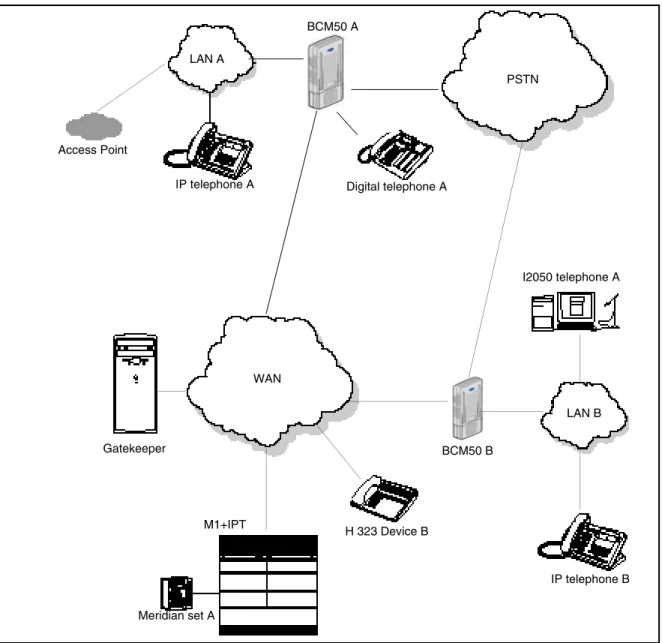
Figure 1 on page 19 shows components of a BCM50 network configuration.
In this example, two BCM50 systems are connected both through a PSTN connection and through a WAN connection. The WAN connection uses VoIP trunks. If the PSTN connections use dedicated ISDN lines, the two systems have backup private networks to each other. Both BCM50 systems use VoIP trunks through a common WAN to connect to the Meridian (M1-IPT) system.
Chapter 2 IP telephone overview 19
Figure 1 Network diagram
Networking with BCM50
The BCM50 is a key building block in creating your communications network. It interoperates with many devices, including the Meridian 1 system and H.323 devices. The BCM50 system can be connected to devices through multiple IP networks, as well as through the PSTN. Multiple BCM50 systems also can be linked together on a network of VoIP trunks and dedicated physical lines.
The BCM50 can be connected to a LAN through a LAN port, to a WAN through the integrated router (Ethernet or ADSL), and to a PSTN through trunk media bay modules, as shown for BCM50 A in the above diagram. Through these networks, the system accesses other systems and network equipment connected to the network.
PSTN LAN B LAN A WAN IP telephone A Gatekeeper BCM50 A IP telephone B M1+IPT H 323 Device B Meridian set A I2050 telephone A Digital telephone A Access Point BCM50 B BCM50 A
M1-IPT
The Meridian 1 Internet Telephony Path (M1-IPT) allows Meridian 1 systems to communicate with the BCM50 through H.323 trunks. Telephones on the M1, such as Meridian set A, can initiate calls to and receive calls from the other telephones on the system across IP networks.
To provide fallback at times when IP traffic cannot pass, you can also connect the Meridian to the BCM50s through ISDN PRI SL-1 lines, which provide the same MCDN capability that you can achieve through the H.323 VoIP trunks with MCDN active.
A BCM50 connected to an M1-IPT using the MCDN protocol can provide access to a central voicemail and call attendant system, which can streamline multi-office telephony administration.
Telephones
The BCM50 can communicate using digital telephones, Norstar M-series telephones, ISDN telephones, analog telephones, and IP telephones (20XX).
While analog and digital telephones cannot be connected to the BCM50 system with an IP connection, they can make and receive calls to and from other systems through VoIP trunks. Calls received through the VoIP trunks to system telephones are received through the LAN or WAN and are translated within the BCM50 to voice channels.
The IP telephones connect to the BCM50 across an IP network through either a LAN or a WAN. From the BCM50 connection, they can then use standard lines or VoIP trunks to communicate to other telephones on other public or private networks. The BCM50 also supports H.323 (version 4) and H.323 third-party devices through this type of connection.
Gatekeepers on the network
A gatekeeper tracks IP addresses of specified devices, and provides routing and (optionally) authorization for making and accepting calls for these devices. A gatekeeper is not required as part of the network to which your BCM50 system is attached, but gatekeepers can be useful on networks with a large number of devices. Referring to Figure 1 on page 19, for example: Digital telephone A wants to call IP telephone B, which is attached to BCM50 B, over a network that is under the control of a gatekeeper. Digital telephone A sends a request to the gatekeeper. The gatekeeper, depending on how it is programmed, provides Digital telephone A with the
information it needs to contact BCM50 B over the network. BCM50 B then passes the call to IP telephone B.
The BCM50 does not contain a gatekeeper application. If you want to install a gatekeeper on your network, it must be put on a separate gatekeeper server. The BCM50 is compatible with CSE 1000 (CSE1K), and NetCentrex gatekeepers.
IP network
In the network shown in Figure 1 on page 19, several LANs and a WAN are shown. When planning your network, be sure to consider all requirements for a data network. Ask your network administrator how to set up your network for the BCM50.
Chapter 2 IP telephone overview 21
WAN
A Wide Area Network (WAN) is a communications network that covers a wide geographic area, such as a state or country. For BCM50, a WAN is any IP network connected to the integrated router on the BCM50 system. This can be a direct connection to another BCM50 system.
If you want to deploy IP telephones that connect to a LAN outside the LAN on which the BCM50 is installed, you must ensure that the BCM50 has a WAN connection. Proper WAN connection includes obtaining IP addresses and routing information that allows the remote telephones to find the BCM50, and vice-versa.
The BCM50 Networking Configuration Guide (N0027156) has a data section that describes the Internet protocols and data settings that the BCM50 requires or is compatible with. Ensure that this connection is correctly set up and working before you attempt to deploy any remote IP devices.
LAN
A Local Area Network (LAN) is a communications network that serves users within a confined geographic area. For BCM50, a LAN is any IP network connected to a LAN port on the BCM50 system. The BCM50a and BCM50e main units include an integrated router that enables you to connect to the Internet.
Public Switched Telephone Network
The Public Switched Telephone Network (PSTN) can play an important role in IP telephony communications. In many installations, the PSTN forms a fallback route. If a call across a VoIP trunk does not have adequate voice quality, the call can be routed across PSTN lines instead, either on public lines or on a dedicated ISDN connection between the two systems (private network). The BCM50 also serves as a gateway to the PSTN for all voice traffic on the system.
Key IP telephony concepts
In traditional telephony, the voice path between two telephones is circuit-switched. This means that the analog or digital connection between the two telephones is dedicated to the call. The voice quality is usually excellent, because there is no other signal to interfere.
In IP telephony, each IP telephone encodes the speech at the handset microphone into small data packets called frames. The system sends the frames across the IP network to the other telephone, where the frames are decoded and played at the handset receiver. If some of the frames get lost while in transit, or are delayed too long, the receiving telephone experiences poor voice quality. On a properly configured network, voice quality must be consistent for all IP calls.
The following sections describe some of the components that determine voice quality for IP telephones and trunks:
• “Codecs” on page 22
Codecs
The algorithm used to compress and decompress voice is embedded in a software entity called a codec (COde-DECode).
Two popular codecs are G.711 and G.729. The G.711 Codec samples voice at 64 kilobits per second (kbps), while G.729 samples at a far lower rate of 8 kbps. For actual bandwidth requirements, refer to the BCM50 Networking Configuration Guide (N0027156); note that the actual kbps requirements are slightly higher than the label suggests.
Voice quality is better when using a G.711 Codec, but more network bandwidth is used to exchange the voice frames between the telephones.
If you experience poor voice quality and you suspect it is due to heavy network traffic, you can achieve better voice quality by configuring the IP telephone to use a G.729 Codec.
The BCM50 supports these codecs:
• G.729
• G.729 with VAD (Voice Activity Detection) • G.711-uLaw
• G.711-aLaw
Jitter Buffer
Voice frames are transmitted at a fixed rate, because the time interval between frames is constant. If the frames arrive at the other end at the same rate, voice quality is perceived as good. In many cases, however, some frames can arrive slightly faster or slower than the other frames. This is called jitter, and degrades the perceived voice quality. To minimize this problem, configure the IP telephone with a jitter buffer for arriving frames.
This is how the jitter buffer works (assume a jitter buffer setting of five frames):
• The IP telephone firmware places the first five arriving frames in the jitter buffer.
• When frame six arrives, the IP telephone firmware places it in the buffer, and sends frame one to the handset speaker.
• When frame seven arrives, the IP telephone buffers it, and sends frame two to the handset speaker.
By using a jitter buffer, the arriving packets are delayed slightly in order to ensure a constant rate of arriving frames at the handset speaker.
Note: You can change the codec on a configured IP telephone only if it is connected to the BCM50, or if Keep DN Alive is enabled for an offline telephone.
Note: You can change the jitter buffer on a configured IP telephone only if it is connected to the BCM50, or if Keep DN Alive is enabled for an offline telephone.
Chapter 2 IP telephone overview 23
This delaying of packets can provide somewhat of a communications challenge, because speech is delayed by the number of frames in the buffer. For one-sided conversations, there are no issues. However, for two-sided conversations, where one party tries to interrupt the other speaking party, by the time the voice of the interrupter reaches the interruptee, the interruptee has spoken (2*jitter size) frames past the intended point of interruption. In cases where very large jitter sizes are used, some users revert to saying OVER when they wish the other party to speak.
Possible jitter buffer settings and corresponding voice packet latency (delay) for the BCM50 system IP telephones are:
• None
• Small (G.711/G.729: 0.06 seconds) • Medium (G711/G.729: 0.12 seconds) • Large (G711/G.729: 0.18 seconds)
25
Chapter 3
Configuring IP telephones
This section describes the procedures for configuring IP telephones. For detailed panel descriptions, refer to “DN records parameters” on page 29.
Refer to the following section for information on configuring IP telephones:
• “Prerequisite programming”
• “IP telephone DN record overview” on page 26
• “Configuring an IP telephone” on page 27
Prerequisite programming
Complete the following programming before you configure the IP telephones. For more
information, refer to BCM50 Networking Configuration Guide (N0027156) and BCM50 Device
Configuration Guide (N0027146). • Numbering plan
• Lines programming
• Telephony system feature programming
IP telephone DN record overview
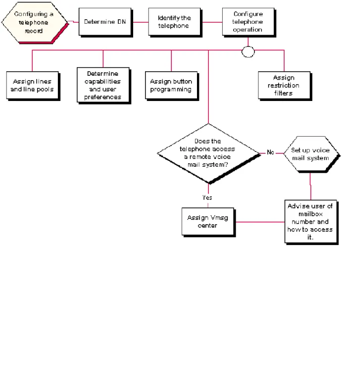
Figure 2 shows an overview of the procedure for configuring a DN record. Figure 2 IP telephone DN record overview
Chapter 3 Configuring IP telephones 27
Configuring an IP telephone
On each panel on the DNs list, add or modify settings to customize the telephone operations.
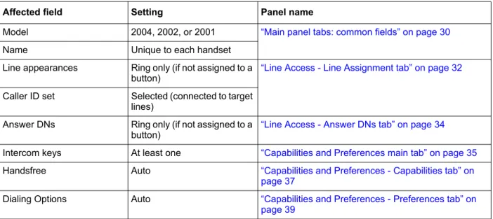
Table 1 lists the fields and settings for IP telephones. Table 1 IP telephone customization
Affected field Setting Panel name
Model 2004, 2002, or 2001 “Main panel tabs: common fields” on page 30 Name Unique to each handset
Line appearances Ring only (if not assigned to a
button) “Line Access - Line Assignment tab” on page 32 Caller ID set Selected (connected to target
lines)
Answer DNs Ring only (if not assigned to a
button) “Line Access - Answer DNs tab” on page 34 Intercom keys At least one “Capabilities and Preferences main tab” on page 35 Handsfree Auto “Capabilities and Preferences - Capabilities tab” on
page 37
Dialing Options Auto “Capabilities and Preferences - Preferences tab” on page 39
29
Chapter 4
DN records parameters
The DN record defines the specific function of each telephone within the system.
The following paths indicate where to access DN record parameters in Element Manager and through Telset Administration:
• Element Manager: Configuration//Telephony//System DNs • Telset interface: **CONFIG//Terminals and Sets
Other areas of programming that affect how each telephone functions include:
• system settings • telephone model
The DN records panel is a multilayered panel with multiple tabs. Although all panels show up for all models, not all models require configuration for all panels.
Refer to the following sections for more information:
• “Main panel tabs: common fields” on page 30
• “Line Access tab” on page 31
Main panel tabs: common fields
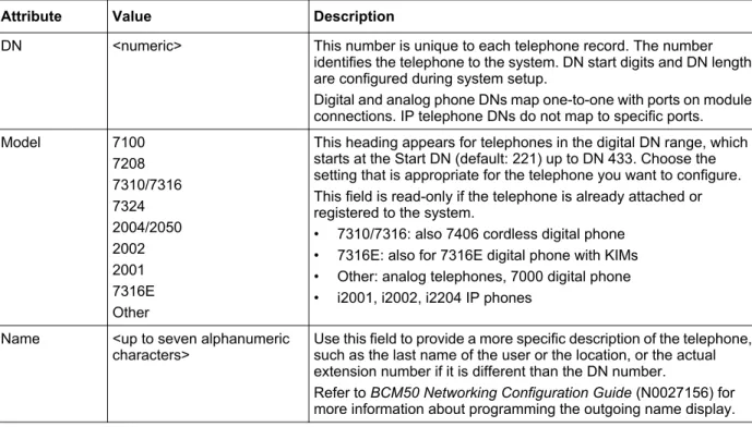
All main panel tabs display the same first three columns, which are shown in Table 2. Table 2 Main panel tabs: common fields descripton
Attribute Value Description
DN <numeric> This number is unique to each telephone record. The number identifies the telephone to the system. DN start digits and DN length are configured during system setup.
Digital and analog phone DNs map one-to-one with ports on module connections. IP telephone DNs do not map to specific ports. Model 7100 7208 7310/7316 7324 2004/2050 2002 2001 7316E Other
This heading appears for telephones in the digital DN range, which starts at the Start DN (default: 221) up to DN 433. Choose the setting that is appropriate for the telephone you want to configure. This field is read-only if the telephone is already attached or registered to the system.
• 7310/7316: also 7406 cordless digital phone • 7316E: also for 7316E digital phone with KIMs • Other: analog telephones, 7000 digital phone • i2001, i2002, i2204 IP phones
Name <up to seven alphanumeric
characters> Use this field to provide a more specific description of the telephone, such as the last name of the user or the location, or the actual extension number if it is different than the DN number.
Refer to BCM50 Networking Configuration Guide (N0027156) for more information about programming the outgoing name display.
Chapter 4 DN records parameters 31
Line Access tab
The Line Access tab displays the System DNs table. Line access programming is performed using the three tabs in the bottom panel. Refer to Figure 3.
Figure 3 System DNs table
Table 3 describes these fields.
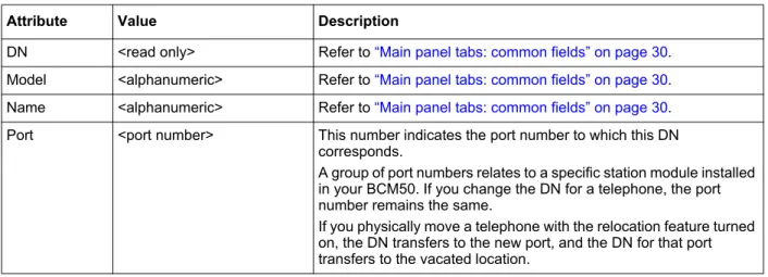
Table 3 Line Access - System DNs table fields (Sheet 1 of 2)
Attribute Value Description
DN <read only> Refer to “Main panel tabs: common fields” on page 30. Model <alphanumeric> Refer to “Main panel tabs: common fields” on page 30. Name <alphanumeric> Refer to “Main panel tabs: common fields” on page 30. Port <port number> This number indicates the port number to which this DN
corresponds.
A group of port numbers relates to a specific station module installed in your BCM50. If you change the DN for a telephone, the port number remains the same.
If you physically move a telephone with the relocation feature turned on, the DN transfers to the new port, and the DN for that port transfers to the vacated location.
Line Access - Line Assignment tab
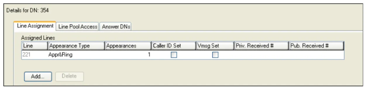
The line assignment setting allows you to assign physical trunks and target lines to each telephone (see Figure 4 on page 33). Target lines are used as incoming only. Other lines can be used to both place and answer calls if they are configured to do so.
Pub. OLI <up to 10 digits> This setting defaults to the DN of the device. The Public Network Code concatenates to the beginning of this number to create the entire public network number. The length of this number is dependent on the country requirements.
This line identification number (OLI) appears on the telephone called from this telephone over the public network. Refer to BCM50 Networking Configuration Guide (N0027156) for more information about public network settings.
North America: If the OLI contains the public network code, the information in the Public Network code field is ignored. Therefore, it is recommended that OLIs be programmed to the public received number length, only. This allows a global change if the Public Network Code is changed.
Refer to BCM50 Networking Configuration Guide (N0027156) for more information about configuring CLID on your system.
Priv. OLI Define the originating line identification number (OLI) that appears on the telephone being called from this telephone over a private network.
Note: On systems running DID, this field is populated automatically with the DN.
On PBX systems, this field is populated automatically only if the DN length and the Received # length are the same.
If the DN length or the Received # length are changed to be different from each other, this field is cleared.
Refer to BCM50 Networking Configuration Guide (N0027156) for more information about configuring CLID on your system. *If your system allows outgoing name and number blocking, the telephone must have a valid OLI. Fwd No
Answer up to 24 digits Enter the number to which you want to redirect unanswered incoming calls. Fwd Delay 2, 3, 4, 6, 10 Define the number of rings before the system forwards an
unanswered call.
This heading only appears after you enter a Call Forward No Answer number and press Enter.
Fwd Busy up to 24 digits Redirect incoming calls when this telephone is busy with another call.
Fwd All up to 24 digits This setting is the same as using FEATURE4 at a telephone. When this feature is active, all calls to this telephone are forwarded to the destination entered in this field.
If you are forwarding calls to a remote location, ensure that you include the required destination/access codes.
A user can press FEATURE#4 to cancel this feature. Table 3 Line Access - System DNs table fields (Sheet 2 of 2)
Chapter 4 DN records parameters 33
Figure 4 Line Access - Line Assignment tabbed panel - Assigned Lines table
Table 4 describes the fields on this panel.
Table 4 Telephone line assignment fields (Sheet 1 of 2) Attribute Values Description
Line <read-only> These are the lines on which this telephone can receive calls. If the line is a two-way line (DID), the user can also use the line to make calls.
Refer to BCM50 Networking Configuration Guide (N0027156) for more information about configuring lines.
Appearance Type Ring only, Appr&Ring,
Appr only Select how a call on this line appears on the telephone.If you choose Appr&Ring or Appr only, you can have as many simultaneous DID calls as there are target line button appearances. If you choose Ring only, you can have as many simultaneous DID calls as you have intercom buttons.
Note: The BCM50 does not support a mixture of Appr only and Ring only appearances for the same line.
7000 or 7100 digital phones default to Ring only. Appearances
(for target lines, only)
<1-10> Select the number of appearances of a target line.
Note: The number of appearances that can be assigned to a telephone depends on how many buttons with indicators are available. Target line appearances cannot overwrite other line appearances, Answer DNs, Intercom buttons, or assigned Handsfree button.
Caller ID set <checkbox> This prompt only appears for target lines, and for any analog lines that provide CLID through a GATM (not all markets).
When enabled, the telephone displays call information when it is available for a call before the call is answered.
When disabled, no call information is displayed for this line until the call is answered. Choose this setting if the telephone does not have a display, or if you do not want call information displayed to the user. Disabling this function can reduce system resource requirements. Limitation: Only 30 telephones can have this field enabled for any given line.
Line Access - Answer DNs tab
Program a telephone to provide automatic call alerting and call answering for other telephones in the system. The DNs of the other telephones are referred to as Answer DNs (see Figure 5). Figure 5 Line Access - Answer DNs tab
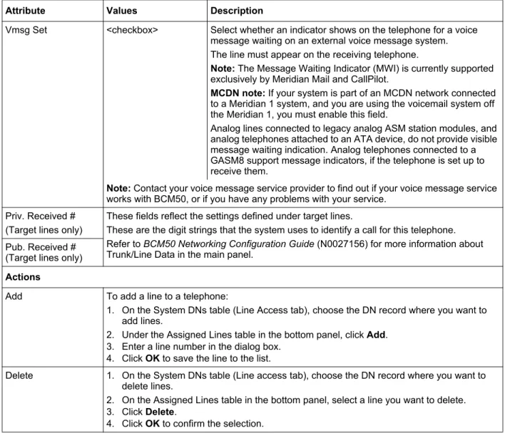
Vmsg Set <checkbox> Select whether an indicator shows on the telephone for a voice message waiting on an external voice message system. The line must appear on the receiving telephone.
Note: The Message Waiting Indicator (MWI) is currently supported exclusively by Meridian Mail and CallPilot.
MCDN note: If your system is part of an MCDN network connected to a Meridian 1 system, and you are using the voicemail system off the Meridian 1, you must enable this field.
Analog lines connected to legacy analog ASM station modules, and analog telephones attached to an ATA device, do not provide visible message waiting indication. Analog telephones connected to a GASM8 support message indicators, if the telephone is set up to receive them.
Note: Contact your voice message service provider to find out if your voice message service works with BCM50, or if you have any problems with your service.
Priv. Received # (Target lines only)
These fields reflect the settings defined under target lines.
These are the digit strings that the system uses to identify a call for this telephone. Refer to BCM50 Networking Configuration Guide (N0027156) for more information about Trunk/Line Data in the main panel.
Pub. Received # (Target lines only) Actions
Add To add a line to a telephone:
1. On the System DNs table (Line Access tab), choose the DN record where you want to add lines.
2. Under the Assigned Lines table in the bottom panel, click Add. 3. Enter a line number in the dialog box.
4. Click OK to save the line to the list.
Delete 1. On the System DNs table (Line access tab), choose the DN record where you want to delete lines.
2. On the Assigned Lines table in the bottom panel, select a line you want to delete. 3. Click Delete.
4. Click OK to confirm the selection. Table 4 Telephone line assignment fields (Sheet 2 of 2)
Chapter 4 DN records parameters 35
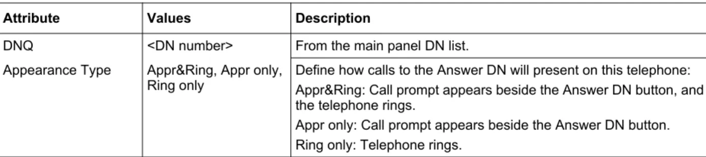
Table 5 describes the access fields on this panel.
Capabilities and Preferences main tab
Capabilities settings control how the system interacts with individual telephones, and how the telephones receive calls.
Preferences control how the telephone itself works. These settings also can be set by users at the telephones using feature codes (see Figure 6 on page 36).
Table 5 Line Pool Access Fields - Answer DNs Attribute Values Description
DNQ <DN number> From the main panel DN list. Appearance Type Appr&Ring, Appr only,
Ring only Define how calls to the Answer DN will present on this telephone:Appr&Ring: Call prompt appears beside the Answer DN button, and the telephone rings.
Appr only: Call prompt appears beside the Answer DN button. Ring only: Telephone rings.
Notes:
Every answer DN you assign to a telephone automatically designates an appearance on the answer telephone beside a button with an indicator, if one is available. Answer DNs overwrite feature assignments to buttons with indicators. They do not overwrite line, Hunt group, intercom, or handsfree assignments.
If no buttons are available on the telephone, ensure that you program the Answer DN as Ring only. In that case, when a call comes in to the other telephone, the user receives a ring tone.
Actions
Add You can add a maximum of eight Answer DNs per telephone.
1. On the System DNs table (Line access tab), choose the DN record where you want to add Answer DNs.
2. Under the Answer DNs table, click Add. 3. Enter the appropriate DN in the dialog box. 4. Click OK to save the entry.
5. On the Answer DNs table, select the Appearance type field beside the Answer DN you just entered and choose the appropriate appearance type.
Programming Note: If the telephone has memory buttons with display designators, the system automatically assigns Answer DNs to buttons starting at the bottom right row of buttons. If the telephone has Handsfree assigned to a memory button, the Answer DNs start above that button. If the telephone has no memory buttons with display, ensure that you choose Ring only as the Appearance type.
Delete 1. On the System DNs table (Line access tab), choose the DN record where you want to delete Answer DNs.
1. On the Answer DNs table, select the Answer DN line you want to delete. 2. Click Delete.
Figure 6 Capabilities and Preferences table panel
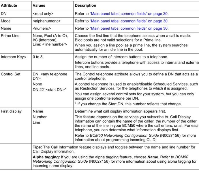
Table 6 describes the fields shown on the main Capabilities and Preferences tabbed panel. Table 6 Capabilities and Preferences tabbed panel (Sheet 1 of 2)
Attribute Values Description
DN <read only> Refer to “Main panel tabs: common fields” on page 30. Model <alphanumeric> Refer to “Main panel tabs: common fields” on page 30. Name <numeric> Refer to “Main panel tabs: common fields” on page 30. Prime Line None, Pool (A to O),
I/C (intercom), Line: <line number>
Choose the first line that the telephone selects when a call is made. Bloc pools are not valid selections for a Prime line.
When you assign a line pool as a prime line, the system searches automatically for an idle line in the pool.
Intercom Keys 0 to 8 Assign the number of intercom buttons to a telephone.
Intercom buttons provide a telephone with access to internal and external lines, and line pools.
Control Set DN: <any telephone DN>
None
DN:221<start DN>*
The Control telephone attribute allows you to define a DN that acts as a control telephone.
A control telephone is used to enable/disable Scheduled Services, such as Restriction Services, for the telephones to which it is assigned. You can assign several control sets for your system, but you can only assign one control telephone per DN.
* If you change the Start DN, this number reflects that change. First display Name
Number Line
Determine what call display information appears first.
This feature depends on the services you subscribe to. Call Display information can contain the name of the caller, the number of the caller, the name of the line in your BCM50 where the call enters, or all. For each telephone, you can determine what information displays first.
Refer to BCM50 Networking Configuration Guide (N0027156) for more information about programming incoming CLID.
Tips: The Call Information feature displays and toggles between the name and line number for Call Display information.
Alpha tagging: If you are using the alpha tagging feature, choose Name. Refer to BCM50 Networking Configuration Guide (N0027156) for more information about using alpha tagging for incoming name display.
Chapter 4 DN records parameters 37
Capabilities and Preferences - Capabilities tab
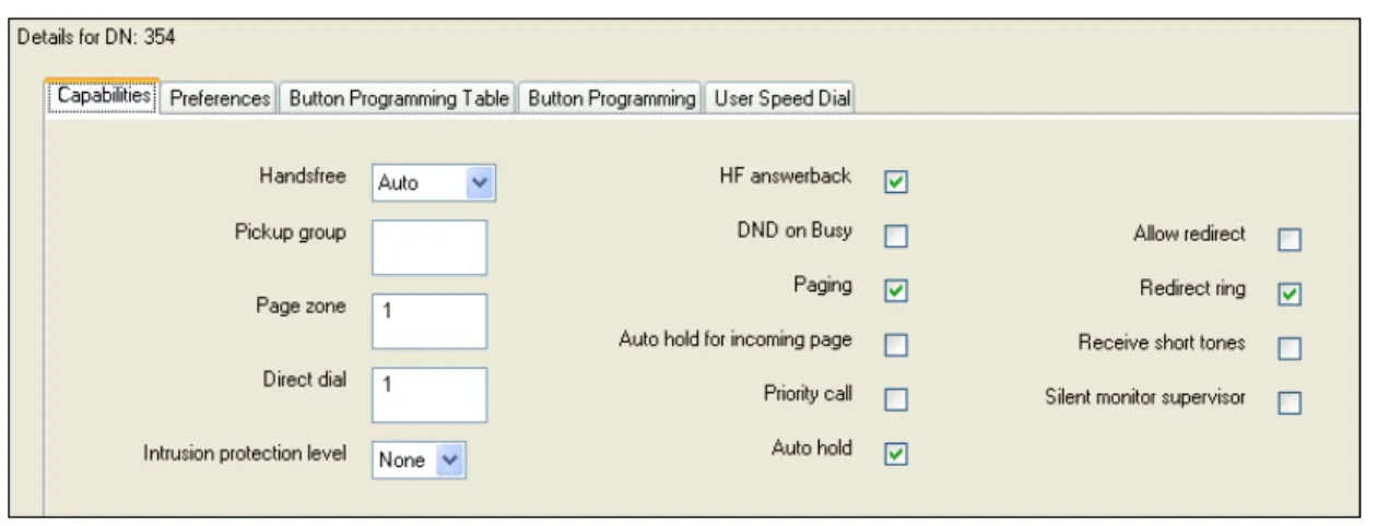
Capabilities settings control how the system interacts with individual telephones, and how the telephones receive calls (see Figure 7).
Figure 7 Capabilities and Preferences - Capabilities tab panel
Table 7 describes the fields on this panel.
Auto Called ID <checkbox> Select whether you want to see on your display the extension number and name of the telephone you call.
The Auto Called ID set for target lines is the same telephone that has an appearance on that target line.
Note: Not all the fields shown below necessarily appear for any one
type of telephone. Some fields relate to specific models of telephones.
Table 7 Capabilities and Preferences - Capabilities panel fields (Sheet 1 of 3) Attribute Values Description
Handsfree None Standard Auto
None: The Handsfree feature is not available to all telephone models (7000 and 7100 digital phones, and 2001 IP phones).
Standard: The Handsfree feature is activated by pressing a button on the telephone.
Auto: The Handsfree feature is activated when the telephone receives a call. Note: Handsfree must be enabled on any telephone that allows headsets. For 7316E digital phones, set Handsfree to Auto.
7406 digital cordless phone: Handsfree must be enabled for this handset to work.
Speaker volume: Note that the speaker volume returns to the telephone default setting for each new handsfree call.
Pickup group None 1 to 9
Assigns this telephone to a pickup group (a group where all telephones ring until one is answered).
Table 6 Capabilities and Preferences tabbed panel (Sheet 2 of 2) Attribute Values Description
Page zone Page zone (1 to 6) None
Assigns this telephone to a page zone.
A zone is any group of telephones that you want to group together for paging, regardless of their location. You can assign one of six zones to each telephone.
The maximum number of digital telephones in a page zone is 50. The maximum number of digital and IP telephones in a page zone is 60. Direct dial Set 1 to
Set 5 None
Defines whether you can call the direct dial telephone from this telephone using the direct dial digit.
Intrustion Protection Level NoneLow
Med High
If the break-in feature is allowed on any private network MCDN lines (PRI SL-1) assigned to the telephone, you must define the level of intrusion for each telephone. This determines if the user can use the feature, and to what degree.
None: feature is turned off, user cannot break in on any calls
Low: user can only break into calls on other telephones with low level protection
Med: user can break into calls on other telephones with low and medium-level protection
High: user can break into calls on all other telephones with this feature HF answerback <checkbox> Defines whether you can answer automatically a voice call without lifting the
receiver or pressing the Handsfree button.
Note: The feature is not available on model i2001, 7000, and 7100 telephones.
Speaker volume: Note that the speaker volume on the telephone returns to the default volume setting determined by the telephone for each new handsfree call.
DND on Busy <checkbox> Defines whether an incoming call rings if you are already on another call. Paging <checkbox> Defines whether you can make paging announcements from this telephone. Auto hold for incoming
page <checkbox> Not selected - If the telephone is active when a page comes in, the page does not come through the telephone set. Selected - If the telephone is active when a page comes in, the call is placed automatically on hold and the page continues.
Note - 7XXX digital phones:
• Condition - When this setting is enabled, an active call is on mute when the page comes in.
• Results after page - The call is taken off hold, but is no longer muted. Priority call <checkbox> Defines whether this telephone can interrupt calls or override Do Not Disturb
at another telephone.
Auto hold <checkbox> This setting determines if the system automatically places an active call on hold if you answer or initiate another call.
If you do not select this box, the system drops the active call, unless you press the HOLD button first when you answer a call or initiate another call. A selected checkbox is the default.
The user can change the Auto hold setting at their telephones by pressing FEATURE 73.
SWCA note: Ensure this setting is selected for any telephones with configured System Wide Call Appearance (SWCA) keys.
Table 7 Capabilities and Preferences - Capabilities panel fields (Sheet 2 of 3) Attribute Values Description
Chapter 4 DN records parameters 39
Capabilities and Preferences - Preferences tab
The Preferences headings allow you to program the same settings that users can perform at their telephones and the settings for configuring a telephone as a hotline. The telset admin options are only available to digital phones and IP telephones (see Figure 8).
Figure 8 Capabilities and Preferences - Preferences tab panel
Allow redirect <checkbox> Define whether this telephone allows assigned lines to be redirected. This must be selected to allow call forwarding outside the network (external call forward), including calls to a centralized voicemail system over a private network.
Redirect ring <checkbox> Define whether the telephone rings briefly when a call on one of its lines is redirected by the Line Redirection feature (FEATURE 84).
Refer to BCM50 Networking Configuration Guide (N0027156) for more information about Trunk/Line Data in the main panel.
Receive short tones <checkbox> Analog equipment that is connected to the system with an internal or external analog terminal adapter (ATA2), responds only to tone dialing signals. Select this setting only if you have analog equipment connected to a station port. Otherwise, do not select Receive short tones.
Silent monitor
supervisor <checkbox> On two-line display telephones only, you can choose whether the telephone can be used to allow the Silent Monitor feature. Select the checkbox to allow this feature on this telephone.
Table 7 Capabilities and Preferences - Capabilities panel fields (Sheet 3 of 3) Attribute Values Description
Table 8 describes the headings on the Preferences panel.
Table 8 Capabilities and Preferences - Preferences panel fields (Sheet 1 of 2)
Setting Values Description
Language Languages displayed are based on
telephone capabilities and system software.
Choose the language for the telephone display prompts.
Dialing options Standard dial Automatic dial Pre-dial
Determine how the telephone handles dialed information. Standard: Lift the receiver and dial.
Automatic dial: Use for devices like fax machines where you want the number to dial out without external cues.
Pre-dial: Dial the numbers, then lift the receiver to allow the telephone to dial the number.
Note: Not all devices show all three options. Contrast 1 through 9 Adjust the contrast of the display.
Ring type 1, 2, 3, or 4 Select a distinctive ring pattern type for the telephone. Default is 1.
Distinct rings in use read only This read-only field indicates the distinct ring patterns are currently in effect, if any, on any lines, telephones, or Hunt groups on the system. Refer to the Warning below.
Warning:
If you assign a distinctive ring pattern to a telephone, and that distinctive ring pattern has already been assigned to a line, all lines with that ring pattern will be reset to None. If you assign a distinctive ring pattern to a line, and that distinctive ring pattern has already been assigned to a telephone, all telephones with that ring pattern will be reset to pattern 1. You also can assign a distinctive ring pattern to a Hunt group.
Aux. ringer <checkbox> Determine whether an auxiliary ringer (if installed) rings for incoming calls at this telephone.
Call log options No autologging No one answered Unanswered by me Log all calls
Select how you want the telephone to handle logging calls. No autologging: No calls are logged automatically. No one answered: Unanswered calls are logged. Unanswered by me: Unanswered calls are logged. Log all calls: All calls are noted in the call log.
Available log space <read-only> This setting indicates the total amount of space available for call logging on the system.
Reset Call Log
Password <button> This button resets the password for the call log if users forget their password. Hotline type None
Internal External
This feature allows you to define a telephone number that
automatically dials when you lift the receiver or press the Handsfree button on a telephone.
Chapter 4 DN records parameters 41
Capabilities and Preferences - IP Terminal Details tab
This is a single-terminal display of the terminal information that is also shown in the Telephony Resources IP Terminal panel (see Figure 9). Refer to BCM50 Networking Configuration Guide (N0027156) for a detailed description of the fields and buttons on this panel.
Figure 9 Capabilities and Preferences - IP Terminal Details panel • Internal DN:*
Direct dial set
Define the internal telephone you want to access.
DN:* The DN of the telephone that is automatically dialed when the user lifts the handset.
Direct dial set: Automatically dials a telephone on the system defined as a direct dial telephone (direct dial access code). Note: If the direct dial telephone is actually on a remote node of the network, ensure that the correct line pools have been assigned to the telephone to properly route the call.
• External External number Enter the complete call number for the external telephone you want to access.
Pool:A Use prime line Use routing table
Enter the line you want the call to use. (This cannot be a target line.)
Pool:A Refer to the line pool assignment for this telephone. Use prime line: Refer to the General record for this telephone. Use routing table: Refer to the routing tables. The routing code for that table must be part of the External number.
Table 8 Capabilities and Preferences - Preferences panel fields (Sheet 2 of 2)
The field is described in Table 9.
Table 9 Capabilities and Preferences - IP Terminal Details
Keep DN alive <checkbox> This feature is only relevant to the Nortel IP telephones (2XXX).
When selected, the system retains the IP telephone DN record even if the IP telephone becomes disconnected. Retention occurs as long as the IP telephone has completed the bootup process. It allows DN-specific features such as Call Forward No Answer and Call Forward on Busy to continue to function even if the telephone is disconnected.
WARNING: If the system is reset, and the IP telephone is disconnected, the feature remains inactive until the telephone is reconnected.
Note: A delay of about 40 seconds occurs between the time when the IP telephone is disconnected and when Keep DN alive becomes active. During this period, incoming calls receive a busy signal or are rerouted to the prime set, depending on system programming. The delay also occurs when the IP telephone is reconnected to the system.
If Keep DN alive is not selected and the IP telephone is disconnected, the DN record becomes inactive. In this case, a Not in Service prompt is produced when special features, such as Call Forward, are invoked.
43
Chapter 5
Registering Nortel 20XX IP telephones
The Nortel 20XX IP telephones must register with the system to be able to use the call features and system features.
Determining the registration process
Registering 20XX IP telephones to the system is a two-stage process.
To register an IP Phone 20XX
1 Set up the system programming to receive registration under Resources//Telephony resources/ /Global Settings tab.
On the Global Settings screen:
a Select the Enable Registration checkbox.
b If you want the installers to use a single password to configure and register the telephone, select the Enable Global Registration Password checkbox, and then enter a numeric password in the Global Password field.
c If you want the system to automatically assign DN records to the telephones, select the
Auto Assign DN checkbox.
2 Configure each telephone (“Configuring telephone settings” on page 44). Note: Ensure that you have loaded the appropriate keycodes to activate the Nortel 20XX IP telephones on your BCM50 system.
Tip: To automatically configure IP Phones with DNs assigned: 1) Set enable registration to ON.
2) Set global registration password to ON. 3) Leave global password field blank. 4) Set auto-assign DN to ON.
Once the IP Phones are operational, set enable registration to OFF.
!
Security Note: Turn Registration and Auto Assign DNs off once the telephone(s) are
registered. Nortel cautions that leaving your IP registration open and unprotected by a password can pose a security risk.
How you configure the telephones depends on whether DHCP is active on the system. — If DHCP (Distributed Host Control Protocol) service on the system is active or the
Customer DHCP server has been configured to hand out the specific system network details, the IP telephone will automatically attempt to find the server. After you register the telephone to the system, as described in “Registering the telephone to the system” on page 44, the telephone assumes the parameters it receives from the system, which are described in “Configuring telephone settings” on page 44.
— If DHCP is not configured to provide system information, or if you are not using DHCP on your network, you must configure your telephone parameters before the telephone can register to the system. In this case, follow the directions in
“Configuring telephone settings” on page 44, and then follow any of the prompts that appear, as described in “Registering the telephone to the system” on page 44. — If an external DHCP server is not present, the DHCP server on the main unit
supplies IP configuration information for all IP devices (PCs and IP Phones). It also supplies specific connection information to the IP Phones.
For more information about DHCP, refer to BCM50 Networking Configuration Guide
(N0027156).
Registering the telephone to the system
When you first connect the telephone to the IP connection, you can receive one of the following:
• If the telephone is not yet registered, and if a password is entered in the Terminal Registration screen, the telephone prompts you for that password.
• If you set Auto Assign DN to OFF, the telephone prompts you for a DN. Refer to
“Configuring IP telephones” on page 25.
• If you are prompted for a password, enter the password and press OK.
• If you are prompted for a DN, enter the DN you want assigned to this telephone and press OK.
When the telephone registers, it downloads the information from the system IP Telephony record to the telephone configuration record. This might include a new firmware download, which occurs automatically. If new firmware downloads, the telephone display indicates the event.
Configuring telephone settings
If you are not automatically registered to the system, you can configure your telephone settings to enable you to access a system on the network. You also must perform these steps if your IP telephone is not connected to the same LAN to which the system is connected.
Note: If the telephone displays a prompt that indicates it cannot find the server,
follow the instructions in Configuring telephone settings on page 44 to enter the specific network path. “To troubleshoot IP telephones” on page 47 describes other possible prompt messages.
Chapter 5 Registering Nortel 20XX IP telephones 45
To access the local configuration menu on a 200X IP telephone
1 Restart the telephone by disconnecting the power, then reconnecting the power.
After about four seconds, the top light flashes and NORTEL NETWORKS appears on the screen. 2 When the greeting appears, immediately, and quickly, press the four display buttons, one
at a time, from left to right. These buttons are located directly under the display.
Press the button sequence within 1.5 seconds or the telephone does not enter configuration mode.
• If Manual Cfg DHCP(0 no, 1 yes) appears on the screen, you successfully accessed the configuration mode.
• If any other message appears, disconnect, then reconnect the power, and try to access the configuration mode again.
3 Enter the network parameters, as prompted.
a As each parameter prompt appears, use the keypad to define values. b Use the * key to enter the period in the IP addresses.
c Press OK to move forward.
d The following table describes the values for each display parameter. Table 10 IP telephone server configurations (Sheet 1 of 2)
Field Value Description
DHCP 0 or 1 Enter 0 if your network is not using a DHCP server to dispense IP addresses. (Partial DHCP)
Enter 1 if your network does use a DHCP server.
If you choose to use a DHCP server rather than allocating static IP addresses for the IP telephones, skip the remainder of this section.
If DHCP = 0
SET IP <ip address> The set IP must be a valid and unused IP address on the network to which the telephone is connected.
NETMASK <subnet mask
address> This is the subnet mask. This setting is critical for locating the system you want to connect to. Display buttons
DEF GW <ip address> Default Gateway on the network (in other words, the nearest router to the telephone. The router for IP address W.X.Y.Z is usually at W.X.Y.1)
If there are no routers between the telephone and the system network adaptor to which it is connected, (for example a direct HUB connection), then enter the Published IP address of the BCM50 as the DEF GW.
If the IP telephone is not connected directly to the Published IP address network adaptor, set the DEF GW to the IP address of the network adaptor to which the telephone is connected. If DHCP = 1
Manual Cfg? DHCP:
Full = 0 Partial = 1
If you indicate DHCP for the telephone, but you want to enter static IP addresses, choose 1 (Partial).
If you choose 0 (Full), the DHCP server assigns IP addresses that are not static.
If DHCP = 0 or Partial
S1 IP <ip address> This is the Published IP address of the first system that you want to register the telephone to.
S1 PORT Default: *7000 This is the port the telephone will use to access this system. S1 ACTION Default: 1
S1 RETRY COUNT <digits between 0
and 255> Set this to the number of times you want the telephone to retry the connection to the system. S2 IP <ip address> This is the Published IP address of the second system that you
want to register the telephone to. It can also be the same as the S1 setting.
S2 PORT Default: *7000 This is the port the telephone will use to access this system. S2 ACTION Default: 1
S2 RETRY COUNT <digits between 0
and 255> Set this to the number of times you want the telephone to retry the connection to the system.
VLAN 0: No VLAN
1: Manual VLAN 2: Automatically discover VLAN using DHCP
Choose 0:NO VLAN if there is no VLAN on the network.
If you do not have DHCP on the network, or if DHCP is supplied by a remote server, select number 1 and enter the VLAN ID*. If you have the system DHCP active on your system, select number 2 if you want DHCP to automatically find the VLAN assignment.
*VLAN is a network routing feature provided by specific types of switches. To find out if VLAN has been deployed on your system, check with your network administrator. If VLAN is deployed, the system administrator responsible for the switch can provide the VLAN ID(s) for your system.
Cfg XAS? 0: No (default) 1: Yes
If you want the telephone to be able to connect to a Net6 service provider server, choose 1. You then are prompted for an IP address for the server.
* Firewall note: Ensure that the firewall filters are set up to enable IP traffic into and out of the system. Table 10 IP telephone server configurations (Sheet 2 of 2)