Ethernet Design Considerations
Solid-state equipment has operational characteristics differing from those of electromechanical equipment. Safety Guidelines for the Application, Installation and Maintenance of Solid State Controls (publication SGI-1.1 available from your local Rockwell Automation sales office or online at http://www.rockwellautomation.com/literature/) describes some important differences between solid-state equipment and hard-wired electromechanical devices. Because of this difference, and also because of the wide variety of uses for solid-state equipment, all persons responsible for applying this equipment must satisfy themselves that each intended application of this equipment is acceptable.
In no event will Rockwell Automation, Inc. be responsible or liable for indirect or consequential damages resulting from the use or application of this equipment.
The examples and diagrams in this manual are included solely for illustrative purposes. Because of the many variables and requirements associated with any particular installation, Rockwell Automation, Inc. cannot assume responsibility or liability for actual use based on the examples and diagrams.
No patent liability is assumed by Rockwell Automation, Inc. with respect to use of information, circuits, equipment, or software described in this manual.
Reproduction of the contents of this manual, in whole or in part, without written permission of Rockwell Automation, Inc., is prohibited.
Throughout this manual, when necessary, we use notes to make you aware of safety considerations.
Allen-Bradley, Rockwell Software, Rockwell Automation, ArmorBlock, CompactLogix, ControlLogix, FactoryTalk, PanelView, RSLinx, RSLogix, Logix5000, Kinetix, FLEX, POINT I/O, PowerFlex, RSNetWorx, RSView, SoftLogix, Stratix 2000, Stratix 5700, Stratix 6000, Stratix 8000, Stratix 8300, ArmorPOINT, POINT Guard I/O, Guard I/O, GuardLogix, Integrated Architecture, ControlFLASH, and TechConnect are trademarks of Rockwell Automation, Inc.
Trademarks not belonging to Rockwell Automation are property of their respective companies.
WARNING: Identifies information about practices or circumstances that can cause an explosion in a hazardous environment, which may lead to personal injury or death, property damage, or economic loss.
ATTENTION: Identifies information about practices or circumstances that can lead to personal injury or death, property damage, or economic loss. Attentions help you identify a hazard, avoid a hazard, and recognize the consequence. SHOCK HAZARD: Labels may be on or inside the equipment, for example, a drive or motor, to alert people that dangerous voltage may be present.
BURN HAZARD: Labels may be on or inside the equipment, for example, a drive or motor, to alert people that surfaces may reach dangerous temperatures.
Summary of Changes
This manual contains new and updated information. Changes throughout this revision are marked by change bars, as shown to the right of this paragraph.New and Updated
Information
This table contains the changes made to this revision.
Topic Page
Studio 5000™ Logix Designer application is the rebranding of RSLogix™ 5000 software 10 Updated switch selection chart 28 Updated information about network address translation (NAT) 38 Added specifications for the 1756-EN2TRXT, 1756-EN2TSC, and 9300-ENA modules 66, 67, 68
Table of Contents
Preface
Studio 5000 Environment . . . 10
Additional Resources . . . 11
Chapter 1
EtherNet/IP Overview
Network Protocols . . . 14
CIP . . . 14
Configuration Requirements. . . 15
IP Address . . . 15
Gateway Address . . . 17
Subnet Mask . . . 18
EtherNet/IP Modules in a Control System . . . 19
Bridge across Networks . . . 20
Chapter 2
Ethernet Infrastructure Components
Topologies . . . 22
Media . . . 24
Hubs. . . 25
Repeaters . . . 25
Media Converters . . . 26
Bridges . . . 26
Routers and Gateways . . . 27
Switches. . . 28
Unmanaged versus Managed Switches. . . 29
Autonegotiation. . . 29
Full-duplex Mode . . . 30
Chapter 3
Ethernet Infrastructure Features
Transmission Packets. . . 32
Default Setting in the Studio 5000 Environment. . . 33
Frames . . . 34
Multicast Address Limit . . . 35
Transmission Protocols. . . 35
Address Resolution Protocol (ARP). . . 35
Domain Name System (DNS) . . . 36
Network Address Translation . . . 38
Allen-Bradley Products That Support NAT . . . 38
Virtual LANs and Segmentation . . . 42
VLAN Trunking . . . 44
VLANs and Segmentation Guidelines. . . 44
Spanning Tree Protocol (STP) and Rapid STP (RSTP) . . . 48
EtherChannel Protocol . . . 49
Flex Links Protocol . . . 50
Resilient Ethernet Protocol (REP) . . . 51
Device-level Ring (DLR) . . . 52
Internet Group Management Protocol (IGMP) . . . 55
Port Security . . . 56
Dynamic Secure MAC Address (MAC ID) . . . 56
Static Secure MAC Address (MAC ID) . . . 56
Security Violations. . . 57
Device Commissioning . . . 58
Chapter 4
EtherNet/IP Protocol
Connections . . . 59
Terminology . . . 61
TCP Connections . . . 62
CIP Connections . . . 62
CIP Connection Message Types . . . 63
CIP Connection Types . . . 63
Nodes on an EtherNet/IP Network . . . 65
EtherNet/IP Network Specifications. . . 66
Packets Rate Capacity . . . 69
EtherNet/IP Capacity Tool . . . 69
Upgrade to Latest Firmware Revision . . . 70
Monitor Packet Sizes in Current Application . . . 70
Requested Packet Interval (RPI) . . . 70
Messaging . . . 71
Implicit Messages . . . 71
Explicit Messages . . . 72
CIP Safety . . . 73
CIP Sync . . . 74
Integrated Motion on an EtherNet/IP Network . . . 76
Connectivity to IT . . . 77
Chapter 5
Predict System Performance
System Prediction Goals . . . 80
Part One: Determine If System Has Sufficient Bandwidth
to Meet Application Requirements. . . 81
Part Two: Predict Maximum input or Output Times for
CIP Connections . . . 82
Performance Calculations . . . 83
CompactLogix 5370 Controller Example . . . 83
ControlLogix Controller Example . . . 84
Identify and Count Connections. . . 85
Calculate Packets/Second . . . 86
Table of Contents
Estimate Maximum Input or Output Times for CIP Connections . 89
Example: Predict System Performance . . . 90
Determine If System Has Sufficient Bandwidth
to Meet Application Requirements . . . 91
Explicit Messaging. . . 92
EtherNet/IP Module Serving as a Scanner . . . 93
EtherNet/IP Modules Functioning as Adapters . . . 95
EtherNet/IP Modules 2 and 3 with Consumed Tags . . . 96
Recommendations to Achieve More Throughput
in an Existing Control System . . . 97
Estimate the Maximum Input or Output Times
for CIP Connections . . . 98
Refine Estimates. . . 99
Preface
Rockwell Automation uses open network technology for seamless, plant-wide integration. These open networks share a universal set of communication services. As a result, information can be communicated seamlessly throughout the plant and to and from the Internet for e-business applications.Each Rockwell Automation network is ideal for a wide range of applications, operates with devices manufactured by various vendors, and shares data with industry-standard information networks.
Comparison EtherNet/IP Network ControlNet Network DeviceNet Network
Function Plant management system tie-in (material handling) with configuration, data collection, and control on a single high-speed network
Supports transmission of time critical data between PLC processors and I/O devices
Connects low-level devices directly to plant-floor controllers without the use of I/O modules
Typical devices networked • Mainframe computers
• Programmable controllers • Robots • HMI • I/O • Drives • Process instruments • Programmable controllers • I/O chassis • HMIs • Personal computers • Drives • Robots • Sensors • Motor starters • Drives • Personal computers • Push buttons • Low-end HMIs
• Bar code readers
• PLC processors
• Valve manifolds Data repetition Large packets, data sent regularly Medium-size packets; data transmissions are
deterministic and repeatable
Small packets; data sent as needed
Number of nodes, max No limit 99 nodes 64 total nodes Data transfer rate 10 Mbps, 100 Mbps, or 1 Gbps 5 Mbps 500, 250, or 125 Kbps Typical use Plant-wide architecture
High-speed applications
Redundant applications Scheduled communication
Supply power and connectivity to low-level devices
Studio 5000 Environment
The Studio 5000 Engineering and Design Environment combines engineering and design elements into a common environment. The first element in the Studio 5000 environment is the Logix Designer application. The Logix Designer application is the rebranding of RSLogix 5000 software and continues to be the product to program Logix5000™ controllers for discrete, process, batch, motion, safety, and drive-based solutions.The Studio 5000 environment is the foundation for the future of Rockwell Automation® engineering design tools and capabilities. It is the one place for design engineers to develop all the elements of their control system.
Preface
Additional Resources
These documents and websites contain additional information concerningrelated products from Rockwell Automation.
You can view or download Rockwell Automation publications at
http:/www.rockwellautomation.com/literature/. To order paper copies of technical documentation, contact your local Allen-Bradley distributor or
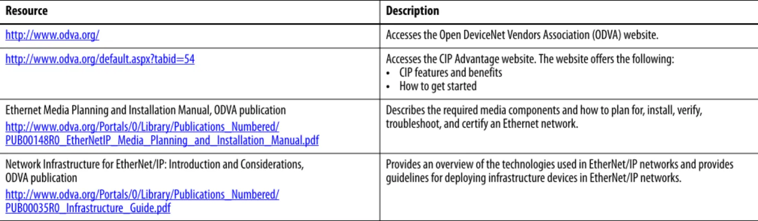
Table 1 - ODVA Resources
Resource Description
http://www.odva.org/ Accesses the Open DeviceNet Vendors Association (ODVA) website.
http://www.odva.org/default.aspx?tabid=54 Accesses the CIP Advantage website. The website offers the following:
• CIP features and benefits
• How to get started Ethernet Media Planning and Installation Manual, ODVA publication
http://www.odva.org/Portals/0/Library/Publications_Numbered/ PUB00148R0_EtherNetIP_Media_Planning_and_Installation_Manual.pdf
Describes the required media components and how to plan for, install, verify, troubleshoot, and certify an Ethernet network.
Network Infrastructure for EtherNet/IP: Introduction and Considerations, ODVA publication
http://www.odva.org/Portals/0/Library/Publications_Numbered/ PUB00035R0_Infrastructure_Guide.pdf
Provides an overview of the technologies used in EtherNet/IP networks and provides guidelines for deploying infrastructure devices in EtherNet/IP networks.
Table 2 - Rockwell Automation Resources
Resource Description
http://www.ab.com/networks/ Accesses the networks and communication section of the Rockwell Automation website.
http://www.rockwellautomation.com/services/networks/ http://www.rockwellautomation.com/services/security/
Accesses Rockwell Automation network and security services websites.
http://www.ab.com/networks/architectures.html Links to the Education series webcasts for IT and controls professionals.
EtherNet/IP Embedded Switch Technology Application Guide, publication ENET-AP005 Describes how to install, configure, and maintain linear and device-level ring (DLR) networks by using EtherNet/IP devices with embedded switch technology. EtherNet/IP QuickConnect Application Technique, publication ENET-AT001 Describes EtherNet/IP QuickConnect technology. QuickConnect technology enables
EtherNet/IP devices to quickly power up and join an EtherNet/IP network. EtherNet/IP Socket Interface Application Technique, publication ENET-AT002 Describes the socket interface used to program MSG instructions to communicate
between a Logix5000 controller via an EtherNet/IP module and Ethernet devices that do not support the EtherNet/IP application protocol.
EtherNet/IP Network Configuration User Manual, publication ENET-UM001 Describes how to configure and use EtherNet/IP communication modules with a Logix5000 controller and communicate with various devices on the Ethernet network.
Table 3 - Cisco and Rockwell Automation Alliance Resources
Resource Description
http://www.ab.com/networks/architectures.html Links to the Rockwell Automation and Cisco Systems reference architecture website. Converged Plantwide Ethernet (CPwE) Design and Implementation Guide,
publicationENET-TD001
Represents a collaborative development effort from Rockwell Automation and Cisco Systems. The design guide is built on, and adds to, design guidelines from the Cisco Ethernet-to-the-Factory (EttF) solution and the Rockwell Automation Integrated Architecture™. The design guide focuses on the manufacturing industry.
Embedded Switch Technology Reference Architectures, publication ENET-RM003 Provides design recommendations for connecting device-level topologies to networks comprised of Layer 2 switches. It also covers the implementation of embedded switch technology within the Converged Plantwide Ethernet (CPwE) Cell/Area zone.
Chapter
1
EtherNet/IP Overview
The EtherNet/IP protocol is a multi-discipline, control and information platform for use in industrial environments and time-critical applications. The EtherNet/IP network uses standard Ethernet and TCP/IP technologies and an open, application-layer protocol called the Common Industrial Protocol (CIP). The open, application-layer protocol makes interoperability and
interchangeability of industrial automation and control devices on the
EtherNet/IP network a reality for automation and real-time control applications.
The EtherNet/IP protocol follows these standards:
• IEEE 802.3—Standard Ethernet, Precision Time Protocol (IEEE-1588)
Topic Page
Network Protocols 14
Configuration Requirements 15
EtherNet/IP Modules in a Control System 19
Bridge across Networks 20
Application Presentation Session Transport Network Link Physical CIP Control and Information
Protocol Ethernet MAC Ethernet Physical UDP TCP IP IP-Multicast EN50170 Control International and IF C 61158 Standard
Request for Comments IETF UDP/TCP/IP
IEEE 802.3
Network Protocols
On the most basic level, Ethernet is a wire or cable that connects computers and peripheral modules so that they can communicate. The actual wire used for the network is referred to as the network medium. Beyond the physical medium, all Ethernet networks support protocols that provide data transfer and network management capability.CIP
CIP is a message-based, application-layer protocol. This protocol implements a relative path to send a message from the producing modules in a system to the consuming modules.
CIP uses the producer/consumer networking model instead of a source/ destination (master/slave) model. The producer/consumer model reduces network traffic and increases speed of transmission.
In traditional I/O systems, controllers poll input modules to obtain their input status. In the CIP system, digital input modules are not polled by a controller. Instead, they produce their data either upon a change of state (COS) or at a requested packet interval (RPI). The frequency of update depends upon the options chosen during configuration and where on the network the input module resides. The input module, therefore, is a producer of input data and the controller is a consumer of the data.
The controller can also produce data for other controllers to consume. The produced and consumed data is accessible by multiple controllers over the Logix backplane and over the EtherNet/IP network. This data exchange conforms to the producer/consumer model.
Protocol Description
Common Industrial Protocol (CIP)
CIP applies a common application layer over an Ethernet network by encapsulating messages in TCP/UDP/IP. This common application layer provides interoperability and interchangeability of industrial automation and control modules on an Ethernet network. The EtherNet/IP network supports both real-time I/O (implicit messaging) and explicit messaging.
Transmission Control Protocol/internet Protocol (TCP/IP)
TCP/IP is a transport-layer protocol (TCP) and a network-layer protocol (IP) commonly used in business environments for communication within networks and across internetworks. The EtherNet/IP communication modules use TCP/IP for explicit messaging. Explicit messaging is used by applications when time is not a critical factor, such as uploading or downloading programs.
User Datagram Protocol/ internet Protocol (UDP/IP)
UDP is a much simpler transport protocol. It is connectionless, and provides a simple means of sending datagrams between two modules. UDP is used by applications that implement their own handshaking between modules and require minimal transport service. UDP is smaller, simpler, and faster than TCP and can operate in unicast, multicast, or broadcast mode. The EtherNet/IP communication modules use UDP/IP for real-time I/O messaging.
EtherNet/IP Overview Chapter 1
Configuration Requirements
All devices on Ethernet communicate by using the Ethernet address for the device. This address is sometimes referred to as the hardware address or Media Access Controller (MAC) address. The hardware address is a unique, six-byte address, which is embedded in the circuitry of every device on an Ethernet network. Every vendor of Ethernet products obtains their own unique address range.For a device to communicate on an Ethernet network, you must configure its IP address, gateway address, and subnet mask.
IP Address
The IP address identifies each node on the IP network or system of connected networks. Each TCP/IP node on a network must have a unique IP address. The IP address is 32 bits long and has a network ID part and a host ID part. Because networks vary in size, there are four types of networks.
The network class determines how an IP address is formatted. Network Type Application
Class A Large networks with many devices Class B Medium-sized networks
Class C Small networks (fewer than 256 devices) Most common for private, industrial networks Class D Multicast addresses
Class A
Class B
Class C
Network (7 bits)
Network (14 bits)
Network (21 bits) Local Address (8 bits) Local Address (16 bits) Local Address (24 bits)
Class D Multicast Address (28 bits) 0 0 8 8 8 8 0 0 0 16 16 16 24 24 24 31 31 31 31 1 0 1 0 1 1 1 0 1 16 24
Each node on the same physical network must have an IP address of the same class and must have the same network ID. Each node on the same network must have a different local address (host ID), thus giving it a unique IP address. IP addresses are written as four-decimal integers (0...255) separated by periods where each integer gives the value of one byte of the IP address.
For example, the following 32-bit IP address is written as 130.0.0.1: 10000010 00000000 00000000 00000001
Public IP addresses are for computers and devices connected to the Internet. Devices on industrial networks are not connected to the Internet, but they communicate with each other over an EtherNet/IP network. These devices use private IP addresses that are not routed on the Internet.
Private IP addresses typically start with 10, 172, or 192 as the first part of the address. Private IP addresses are typically connected to the Internet through a Network Address Translation (NAT) device.
For more information about NAT, see page 38.
Class Leftmost Bits Start Address Finish Address
A 0xxx 0.0.0. 127.255.255.255
B 10xx 128.0.0.0 191.255.255.255
C 110x 192.0.0.0 223.255.255.255
EtherNet/IP Overview Chapter 1
Gateway Address
A gateway connects individual physical networks into a system of networks. When a node needs to communicate with a node on another network, a gateway transfers the data between the two networks. The following figure shows gateway G connecting Network 1 with Network 2.
When host B with IP address 128.2.0.1 communicates with host C, it knows from C’s IP address that C is on the same network. In an Ethernet environment, B can then resolve C’s IP address to a MAC address and communicate with C directly.
When host B communicates with host A, it knows from A’s IP address that A is on another network because the network IDs differ. To send data to A, B must have the IP address of the gateway connecting the two networks. In this example, the gateway’s IP address on Network 2 is 128.2.0.3.
The gateway has two IP addresses (128.1.0.2 and 128.2.0.3). Network 1 hosts must use the first IP address, and Network 2 hosts must use the second IP address. To be usable, a host’s gateway IP address must match its own net ID. Devices with IP address switches use the default gateway address of either 192.168.1.1 or 0.0.0.0. Check your product information to determine which gateway address applies for your device.
Network 1 Network 2 A B C G 128.1.0.2 128.2.0.3 128.2.0.2 128.2.0.1 128.1.0.1
Subnet Mask
Subnet addressing is an extension of the IP address scheme. It enables a site to use a single net ID for multiple physical networks. Routing outside of the site continues by dividing the IP address into a net ID and a host ID via the IP class. Inside a site, the subnet mask is used to redivide the IP address into a custom net ID portion and host ID portion.
A subnet mask determines which of the 32 bits in the IP address are part of the network ID and which are part of the unique node identification. This also determines the size of the network or subnetwork.
Take Network 2 (a Class B network) in the previous example and add another physical network. Selecting this subnet mask adds two additional net ID bits providing for four physical networks.
11111111 11111111 11111111 00000000 = 255.255.255.0
Two bits of the Class B host ID have been used to extend the net ID. Each unique combination of bits in the part of the host ID where subnet mask bits are 1 specifies a different physical network.
A second network with hosts D and E has been added. Gateway G2 connects network 2.1 with network 2.2. Hosts D and E use gateway G2 to communicate with hosts not on network 2.2. Hosts B and C use gateway G to communicate with hosts not on network 2.1. When B is communicating with D, G (the configured gateway for B) routes the data from B to D through G2.
128.1.0.1 128.2.64.1 128.2.64.3 128.1.0.2 Network 1 Network 2.1 128.2.128.1 128.2.128.2 128.2.128.3 128.2.64.4 128.1.0.1 128.2.64.1 128.2.128.1 128.2.64.2 128.2.128.2 128.1.0.2 128.2.64.3 128.2.128.3 A B C G G2 D E Network 2.2
EtherNet/IP Overview Chapter 1
EtherNet/IP Modules in a
Control System
The following diagram shows how EtherNet/IP communication modules can fit into a control system.
In this example, the following actions can occur:
• Controllers produce and consume tags with each other.
• Controllers initiate MSG instructions to send/receive data or configure devices.
• Controllers control I/O and drives.
• Workstations can upload/download projects to the controllers.
• Workstations can configure devices on the EtherNet/IP network.
Switch 1756-EN2T 1756 I/O Modules 1794-AENT 1794 I/O Modules Workstation 1734-AENT 1734 I/O Modules PowerFlex® Drive 1783-ETAP Workstation 1783-ETAP 1756-EN2TR 1756 I/O Modules
1769-L18ERM-BB1B Control System
1769-L33ERM Control System
PanelView™ Plus Terminal Connected Via a 1783-ETAP EtherNet/IP Tap
1794-AENTR FLEX™ I/O Adapter 1734-AENTR POINT I/O™ Adapter
with POINT I/O Modules Kinetix 6500 Drives
with Motors
Kinetix 350 Drive with Motor
Bridge across Networks
Some EtherNet/IP communication modules support the ability to bridge or route communication through devices, depending on the capabilities of the platform and communication devices.You have a bridge when you have a connection between communication devices on two networks. For example, the bridge device has both EtherNet/IP and DeviceNet connections, enabling Device 1 on the EtherNet/IP network to communicate with Device 2 on a DeviceNet network through the bridge. The bridge device can be an EtherNet/IP-to-DeviceNet bridging device or a Logix5000 system with an EtherNet/IP communication module and a DeviceNet communication module.
In the following example graphic, a workstation configures a drive on a DeviceNet network and bridges EtherNet/IP networks to reach the drive.
CIP messages originating on this network Can bridge to this network
EtherNet/IP ControlNet DeviceNet RS-232 Serial
EtherNet/IP Yes Yes Yes Yes
ControlNet Yes Yes Yes Yes
RS-232 Yes Yes Yes Yes
IMPORTANT You can bridge between devices on different networks for only messaging. You cannot bridge from one network to another for I/O control or produced and consumed tags. This restriction applies regardless of whether the two networks are either of the following:
• Same type, such as an EtherNet/IP network to an EtherNet/IP network • Different types, such as an EtherNet/IP network to a ControlNet network
Bridge EtherNet/IP PanelView Plus Terminal DeviceNet Drive Switch
Chapter
2
Ethernet Infrastructure Components
The topology and cable layout of the Ethernet network is part of the physical layer. Ethernet systems require various infrastructure components to connect individual network segments.
Topic Page Topologies 22 Media 24 Hubs 25 Repeaters 25 Media Converters 26 Bridges 26
Routers and Gateways 27
Topologies
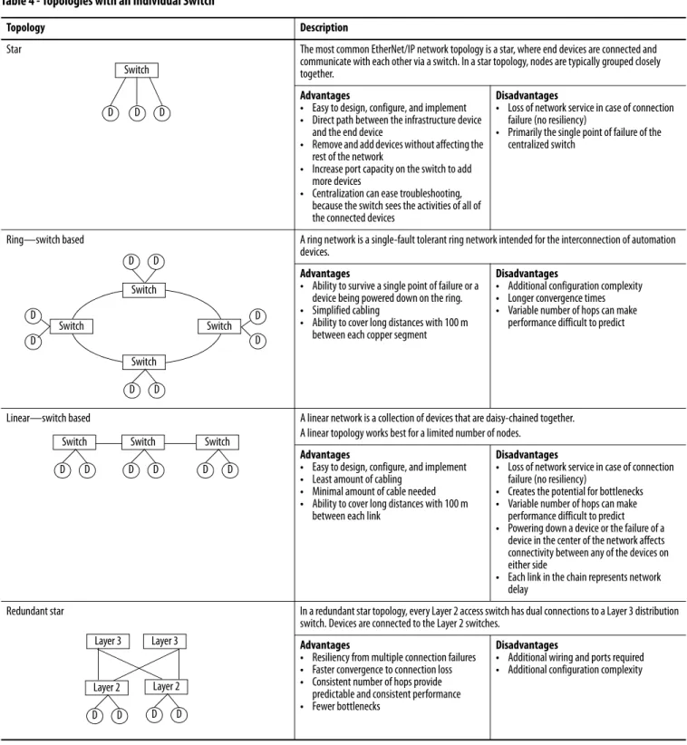
Ethernet networks are laid out in point-to-point configurations with one cable for each device. Ethernet networks have active infrastructures that rely on switches. You can design a network with individual switch devices and devices with embedded switch technology.Table 4 - Topologies with an Individual Switch
Topology Description
Star The most common EtherNet/IP network topology is a star, where end devices are connected and communicate with each other via a switch. In a star topology, nodes are typically grouped closely together.
Advantages
• Easy to design, configure, and implement
• Direct path between the infrastructure device and the end device
• Remove and add devices without affecting the rest of the network
• Increase port capacity on the switch to add more devices
• Centralization can ease troubleshooting, because the switch sees the activities of all of the connected devices
Disadvantages
• Loss of network service in case of connection failure (no resiliency)
• Primarily the single point of failure of the centralized switch
Ring—switch based A ring network is a single-fault tolerant ring network intended for the interconnection of automation devices.
Advantages
• Ability to survive a single point of failure or a device being powered down on the ring.
• Simplified cabling
• Ability to cover long distances with 100 m between each copper segment
Disadvantages
• Additional configuration complexity
• Longer convergence times
• Variable number of hops can make performance difficult to predict
Linear—switch based A linear network is a collection of devices that are daisy-chained together. A linear topology works best for a limited number of nodes.
Advantages
• Easy to design, configure, and implement
• Least amount of cabling
• Minimal amount of cable needed
• Ability to cover long distances with 100 m between each link
Disadvantages
• Loss of network service in case of connection failure (no resiliency)
• Creates the potential for bottlenecks
• Variable number of hops can make performance difficult to predict
• Powering down a device or the failure of a device in the center of the network affects connectivity between any of the devices on either side
• Each link in the chain represents network delay
Redundant star In a redundant star topology, every Layer 2 access switch has dual connections to a Layer 3 distribution switch. Devices are connected to the Layer 2 switches.
Advantages
• Resiliency from multiple connection failures
• Faster convergence to connection loss
• Consistent number of hops provide predictable and consistent performance
• Fewer bottlenecks
Disadvantages
• Additional wiring and ports required
• Additional configuration complexity Switch D D D D D Switch Switch Switch Switch D D D D D D Switch D D Switch D D Switch D D Layer 3 Layer 3 Layer 2 D D Layer 2 D D
Ethernet Infrastructure Components Chapter 2
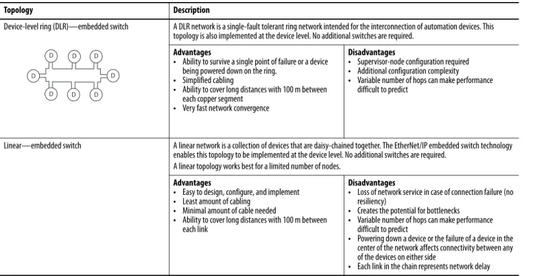
The EtherNet/IP embedded switch technology offers alternative network topologies by embedding switches into the end devices themselves.
Table 5 - Topologies with Embedded Switch Technology
Topology Description
Device-level ring (DLR)—embedded switch A DLR network is a single-fault tolerant ring network intended for the interconnection of automation devices. This topology is also implemented at the device level. No additional switches are required.
Advantages
• Ability to survive a single point of failure or a device being powered down on the ring.
• Simplified cabling
• Ability to cover long distances with 100 m between each copper segment
• Very fast network convergence
Disadvantages
• Supervisor-node configuration required
• Additional configuration complexity
• Variable number of hops can make performance difficult to predict
Linear—embedded switch A linear network is a collection of devices that are daisy-chained together. The EtherNet/IP embedded switch technology enables this topology to be implemented at the device level. No additional switches are required.
A linear topology works best for a limited number of nodes.
Advantages
• Easy to design, configure, and implement
• Least amount of cabling
• Minimal amount of cable needed
• Ability to cover long distances with 100 m between each link
Disadvantages
• Loss of network service in case of connection failure (no resiliency)
• Creates the potential for bottlenecks
• Variable number of hops can make performance difficult to predict
• Powering down a device or the failure of a device in the center of the network affects connectivity between any of the devices on either side
• Each link in the chain represents network delay
D D D
D D
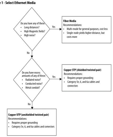
Media
The actual wire used for the network is referred to as the physical media. Generally, shorter cable runs are less susceptible to EMI (electromagnetic interference) and RFI (radio-frequency interference) from electrical circuits, motors, and other machinery.Figure 1 - Select Ethernet Media
For more information about the media options, see the Ethernet section of the Network Media Catalog, publication M116-CA552.
Do you have any of these:
• Long distances?
• High Magnetic fields?
• High noise?
Fiber Media
Recommendations:
• Multi-mode for general purposes, cost less
• Single-node yields higher distance, but costs more
Do you have excess amounts of any of these:
• Radiated noise?
• Conducted noise?
• Metal conduit?
Copper STP (shielded twisted pair)
Recommendations:
• Requires proper grounding
• Category 5e, 6, and 6a cables and connectors
Copper UTP (unshielded twisted pair)
Recommendations:
• Requires proper grounding
• Category 5e, 6, and 6a cables and comectors Yes
Yes No
Ethernet Infrastructure Components Chapter 2
Hubs
Hubs are multiport repeaters. They are based on older technology, which hasbeen largely replaced by network switches at Layer 2, but they are still used as network diagnostic tools to analyze network traffic:
• A hub is at the center of a star topology.
• Hubs can connect together with a variety of media as a backbone between hubs.
• A hub broadcasts everything it receives on any channel out all other channels.
Repeaters
A repeater recreates the incoming signal and re-transmits it without noise ordistortion that can have affected the signal as it was transmitted down the cable. Repeaters are generally used in older networks to increase the network length. More modern networks use fiber media or switches to increase network length.
Hub HMI 1756 Controller 1734 POINT I/O PowerFlex 1738 ArmorPOINT® I/O Personal computer Repeater
Media Converters
Media converters let you mix fiber and copper (twisted-pair) cables in the same system.Use a switch to mix media:
• Physical layer devices offer no buffering or advanced diagnostic features.
• Physical layer devices are easily overrun by an EtherNet/IP system (no buffering = lost data).
• Layer 2 devices have buffering, QoS, and other management features.
Bridges
A bridge is a device that isolates traffic between segments by selectivelyforwarding frames to their proper destination. A bridge is transparent to the network and protocol independent. More advanced devices that perform the same bridging function are commonly used instead of a bridge.
Fiber Link Ethernet Ethernet Ethernet Token Ring Bridge Bridge Ethernet Ethernet
Ethernet Infrastructure Components Chapter 2
Routers and Gateways
Routers and gateways use the network portion of IP addresses to identify thelocation of networks. A routing table lets a device know from which port to transmit a message, so the message can get to a particular network. If that network is not directly attached to the device, it forwards the message to the next gateway or router in the path for further routing.
Routing Table Network Port 10.17.10.0 10.10.10.0 1 2 10.17.10.56 VLAN 17 Subnet 10.17.10.0 Subnet Mask 255.255.255.0 10.10.10.56 Default Gateway 10.10.10.1 10.17.10.1 VLAN 10 Subnet 10.10.10.0 Subnet Mask 255.255.255.0
Switches
Switches provide determinism and throughput required for control applications. Industrial-rated switches are recommended for connecting computers and other devices to each other and to higher-level networks in the network reference architecture. Ethernet switches perform the following:• Operate in Full-duplex mode to eliminate collisions
• Include managed switch features for advanced network functionality
Figure 2 - Select an Ethernet Switch
For more information, see the Stratix Switch Reference Chart, publication
ENET-QR001. Yes No Yes No No
Do you connect to another network infrastructure device, such as a switch or router?
Do you need Layer 3 routing?
Select a Stratix 8300 modular, managed switch:
• 1783-RMS06T 4 ports copper, 2 ports copper/fiber
• 1783-RMS10T 8 ports copper, 2 ports copper/fiber Optionally, add expansion ports:
• 1783-MX08T 8 ports copper
• 1783-MX08F 8 ports fiber
• 1783-MX04S 4 ports SFP
• 1783-MX08S 8 ports SFP
• 1783-MX04E 4 ports PoE
• 1783-MX4T04E 4 ports PoE + 4 ports 10/100
Select a Stratix 8000 modular, managed switch:
• 1783-MS06T • 1783-MS10T
Optionally, add expansion ports:
• 1783-MX08T 8 ports
• 1783-MX08F 8 ports copper
• 1783-MX04S 4 ports SFP
• 1783-MX04E 4 ports PoE
• 1783-MX4T04E 4 ports PoE + 4 ports 10/100 Do you need any of these:
• Network segmentation
• Diagnostic information
• Port security
• Traffic management
• Network resiliency
Do you need any of these?
• More than 20 ports
• More than 4 fiber ports
• More than 4 PoE ports
Select a Stratix 2000™ unmanaged switch:
• 1783-US03T01F 3 ports copper, 1 port fiber
• 1783-US05T 5 ports copper
• 1783-US06T01F 6 ports copper, 1 port fiber
• 1783-US08T 8 ports copper
Select a Stratix 5700 configurable, managed switch:
• 1783-BMSxxx 6 port versions • 1783-BMSxxx 10 port versions • 1783-BMSxxx 20 port versions Yes No Yes
Ethernet Infrastructure Components Chapter 2
Unmanaged versus Managed Switches
Unmanaged switches are relatively inexpensive and simple to set up, but they do not provide any management capabilities, security, or diagnostic information. Therefore, they are difficult to troubleshoot.
As a general rule for unmanaged switches, make sure of the following:
• Your application does not contain I/O traffic or
• Your application has I/O control and the following is true:
– The network is not directly connected to the IT network
– All nodes on the network are Rockwell Automation devices
– There is no potential to overload a device with traffic
Managed switches are typically more expensive than unmanaged switches and require some level of support for initial configuration and replacement. However, managed switches provide advanced features, which can enable better network performance in your control system. Managed switches are able to manage multicast traffic and provide diagnostics data, security options, and other advanced features.
Autonegotiation
Autonegotiation lets devices select the optimal way to communicate without requiring you to configure the devices. However, if you connect a
manually-configured device to an autonegotiation device, a high rate of data transmission errors can occur.
All 100 Mbps devices are required to support autonegotiation, but most existing 10 Mbps devices do not. Select a switch that supports both speeds to enable you to connect to existing devices that use the slower rate.
Switch Type Advantages Disadvantages
Managed • Ability to manage multicast traffic
• Diagnostics data
• Security options
• Additional advanced features
• Network segmentation features
• Network resiliency features
• More expensive
• Requires some level of support and configuration to start up and replace
Unmanaged • Inexpensive
• Simple to set up
• 'No Config' replacement
• No network segmentation
• No dagnostic information
• No port security
• No traffic management
Full-duplex Mode
Ethernet is based on Carrier Sense Multiple Access/Collision Detect (CSMA/ CD) technology. This technology places all nodes on a common circuit so they can all communicate as needed. The nodes must handle collisions (multiple devices talking at the same time) and monitor their own transmissions so that other nodes have transmission time.
The data transmission mode you configure determines how devices transmit and receive data.
Full-duplex mode eliminates collisions. Combined with the speed of the switches available today, you can eliminate the delays related to collisions or traffic in the switch. A a result, the EtherNet/IP network becomes a highly deterministic network well-suited for I/O control:
• If you are autonegotiating, make sure you verify the connection.
• If you are forcing speed and duplex on any link, make sure you force at both ends of the link. If you force on one side of the link, the
autonegotiating side always goes to half-duplex. Transmission Mode Features
Full-duplex Deterministic
• Transmit and receive at the same time
• Transmit on the transmit pair and receive on the receive pairs
• No collision detection, backoff, or retry
• Collision free Half- duplex Nondeterministic
• One station transmits and the others listen
• While transmitting, you do not receive, as no one else is transmitting
• If someone else transmits while you are transmitting, then a collision occurs
Chapter
3
Ethernet Infrastructure Features
When you use the EtherNet/IP network for time-critical control, there are several features available in switches that are required or recommended.
Topic Page
Transmission Packets 32
Transmission Protocols 35
Network Address Translation 38
Virtual LANs and Segmentation 42
Quality of Service (QoS) 45
Resiliency 46
Internet Group Management Protocol (IGMP) 55
Port Security 56
Transmission Packets
Data is transmitted over the EtherNet/IP network in packets. There are transmission methods for transporting data on the network.Packet Type Destination Description
Unicast A single node Unicast connections are point-to-point transmissions between a source node and destination node on the network. A frame is sent to a single destination.
Multicast Multiple nodes simultaneously
Multicast connections deliver information from one sender to multiple receivers simultaneously. Copies of a single frame are passed to a selected subset of possible destinations.
Broadcast All nodes Broadcast connections transmit information to every device on the network. A frame is delivered to all hosts on the network.
Ethernet Infrastructure Features Chapter 3
Limit the amount of broadcast and multicast traffic on the supervisory control network:
• Eliminating unwanted traffic reduces the load on devices, switches, and the network.
• Eliminating unnecessary incoming broadcast traffic also minimizes network load.
It is important to prevent network traffic from coming into the supervisory control (level 2) and manufacturing operations (level 3) network from other levels. Likewise, it is equally important to make sure that traffic on the control system network does not get propagated into the plant enterprise network
Default Setting in the Studio 5000 Environment
The support for unicast communication and the default settings in the Studio 5000 environment depend on the version of software. Later versions include the unicast features of earlier versions.
For a compatibility chart of products see Knowledgebase answer ID 66324 at
http://www.rockwellautomation.com/knowledgebase/. Studio 5000 Version Unicast Support and Default Setting
20.01.00 Safety I/O unicast support added Unicast default
19.01.00 Safety produce/consume unicast support added Unicast default
18.02.00 Standard I/O unicast support added Multicast default
16.03.00 Standard produce/consume unicast support added Multicast default
Frames
Use multicast frames in these situations:
• Redundancy applications
• Communication with more than one destination
Multicast is more efficient than sending multiple, unicast streams to multiple nodes.
• Video streaming
You must use unicast communication if the transmission routes through a Layer 3 device.
I/O devices generally produce at very fast rates, such as 10 ms, so it is easy to flood the network with multicast traffic and force each end device to spend time deciding whether to discard numerous multicast frames. If there are a lot of I/O devices, they can easily use up a significant part of a router’s CPU time.
You must consider control network traffic propagating onto the plant
information network, as well as, plant information network traffic propagating onto the control network. Some best practices include the following:
• Minimize device load due to unwanted IP multicast traffic
• Minimize switch load due to unwanted IP multicast traffic
• Minimize network load due to unwanted incoming IP multicast or broadcast traffic
• Block IP multicast traffic generated within the EtherNet/IP subnet from propagating onto the plant network
• Implement standard network troubleshooting tools
For more information, see Virtual LANs and Segmentation on page 42 and
Layer 2 Switch Layer 2 Switch I/O (producer) Controller (consumer) Switch or Router To Plant Network
Ethernet Infrastructure Features Chapter 3
Multicast Address Limit
In multicast communication, EtherNet/IP interfaces support a maximum of 32 devices that transmit multicast.
The multicast address limit is independent of the connection limit for a device. Not all connections require a multicast address. In the case of produced and consumed tags, one produced tag requires one multicast address, but it also requires one connection for each consumer. If there are multiple consumers, the one multicast address must use multiple connections.
Transmission Protocols
The network layer (Layer 3) provides switching and routing that create logicalpaths, known as virtual circuits, for transmitting data from node to node. Routing and forwarding are functions of this layer, as well as addressing and internetworking.
Address Resolution Protocol (ARP)
An ARP request is a broadcast message that asks ‘who has this IP address?’. The device that has that IP address responds and the requestor adds the IP address and hardware address pair to its ARP cache. The original device can now send the message. This protocol enables the network to learn and adapt to changes.
EXAMPLE An Ethernet adapter that produces data uses a unique multicast address for each I/O connection.
EXAMPLE A Logix controller that produces tags uses a unique multicast address for each produced tag.
1756 Controller
1756 Controller
Device needs to send a message to 130.151.3.4
Who has the IP address 130.151.3.4 ?
I ha
addr
13
0.15
If you replace a Rockwell Automation EtherNet/IP communication module with a new module, the new module has a different MAC ID. The ARP cache entries in other devices are now invalid because the MAC ID corresponding to the module's IP address has changed. This can cause a delay in reestablishing communication with the replacement module. The delay varies depending on the module and the network configuration in use.
When a Rockwell Automation EtherNet/IP device starts up, it issues a gratuitous ARP that causes other devices to update their ARP caches. This generally results in a quick recovery of communication with the replacement module (less than a minute). However, some switches do not forward the gratuitous ARP message onto the network, such as if the Spanning Tree Protocol is enabled on that port. We recommend that you disable the Spanning Tree Protocol on ports to which EtherNet/IP communication modules are directly connected, but not on ports that are linked to other switches. In the worst case, if the gratuitous ARP is not seen, an originating device can wait as long as 10 minutes for the ARP cache entry to age out and be deleted.
Domain Name System (DNS)
DNS is a name resolution protocol that enables you to identify devices by names rather than IP addresses. For DNS to work, a DNS server is configured to hold a table of names and the associated IP addresses. When a device attempts to send a message to a device with an unknown name, it requests the IP address of the named device from the DNS server.
DNS Server
What is the IP address for the PowerFlex drive?
1756 Controller
The controller needs to send a message to the PowerFlex drive.
1734 POINT I/O
PowerFlex Drive 130.151.3.4
Ethernet Infrastructure Features Chapter 3
The DNS server refers to its table and sends back an IP address for the requested name. Once the client device receives the IP address for a name, it stores it in its own table so it does not have to ask for the IP address every time. The device still sends an ARP request if it needs to decode the IP address into a hardware address.
DNS Server I have IP address 130.151.3.4 1756 Controller 1734 POINT I/O PowerFlex Drive 130.151.3.4 DNS Table Name IP Address Controller 130.151.3.5 PowerFlex Drive 130.151.3.5 POINT I/O 130.151.3.5
Network Address Translation
Network address translation (NAT) enables a single device to act as an agent between the public network (commonly the plant network) and the private network (machine network). This facilitates communication between a group of computers with preset IP addresses on a private network by mapping each preset IP address to a valid IP address on the public network.These are two types of NAT implementations:
• One-to-many—Multiple nodes are mapped to a single public identity to get onto the Internet, such as in a home network. This type of
implementation conserves public IP addresses and offers some protection against attacks from the Internet.
• One-to-one—Each node on the network translates to another identity on another network. This type of implementation is used in manufacturing to integrate machinery onto a larger network without requiring addressing changes at the machine level.
Allen-Bradley Products That Support NAT
The table summarizes features of the two products that support one-to-one NAT. Feature 9300-ENA Device Stratix 5700 Switch
NAT architecture Standalone device Integrated into switch hardware Performance 500 messages/s Wire-speed translations Number of translations, max 128 128 devices or subnets(1)
(1) One subnet translation can include translations for 16…65,000 devices.
Supported network topologies Star • Star
• Redundant star
• Ring
Configuration Web interface • Device Manager Web interface
• Studio 5000 environment
Ethernet Infrastructure Features Chapter 3
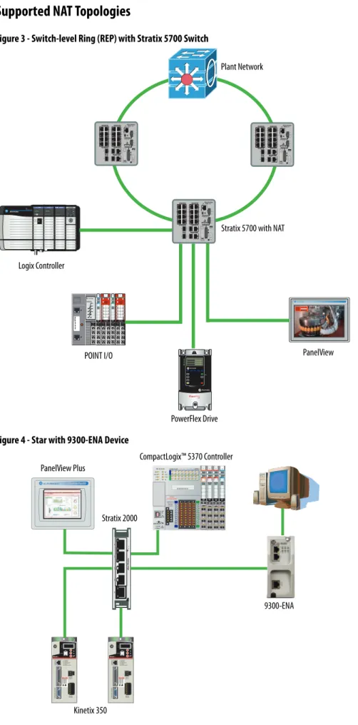
Supported NAT Topologies
Figure 3 - Switch-level Ring (REP) with Stratix 5700 Switch
Figure 4 - Star with 9300-ENA Device
Logix Controller
Stratix 5700 with NAT
PanelView POINT I/O Plant Network PowerFlex Drive CompactLogix™ 5370 Controller PanelView Plus Stratix 2000 9300-ENA
Figure 5 - Star with Stratix 5700 Switch
Figure 6 - Redundant Star with Stratix 5700 Switch
Stratix 5700 with NAT Plant Network
Logix Controller
PanelView POINT I/O PowerFlex Drive
Stratix 5700 with NAT Plant Network
Ethernet Infrastructure Features Chapter 3
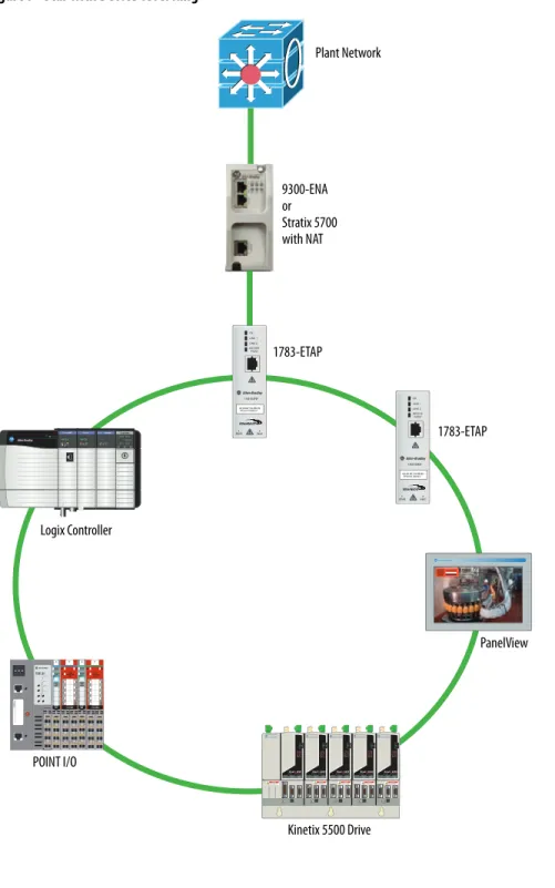
Figure 7 - Star with Device-level Ring
POINT I/O Plant Network 1783-ETAP Kinetix 5500 Drive 1783-ETAP 9300-ENA or Stratix 5700 with NAT PanelView Logix Controller
Virtual LANs and
Segmentation
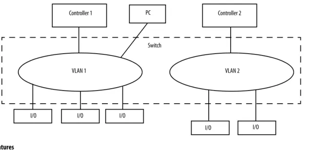
A virtual LAN (VLAN) is a switched network segmented on a functional application or organizational basis rather than a physical or geographical basis. Switches filter destination MAC addresses and forward VLAN frames to ports that serve the VLAN only to which the traffic belongs. A VLAN consists of several end systems. These systems are either hosts or network equipment, such as switches and routers, that are members of a single logical broadcast domain. A VLAN does not have physical proximity constraints for the broadcast domain. With VLANs, you can configure a switch to share two isolated networks without the traffic from one network burdening the other. IP multicast traffic from VLAN 1 does not reach VLAN 2. A VLAN blocks broadcast traffic and adds a measure of security between networks.
A VLAN also gives you the ability to control access and security to a group of devices independent of their physical location.
Segmentation is the process of outlining which endpoints need to be in the same LAN. Segmentation is a key consideration for a cell or area network.
Segmentation is important to help manage the real-time communication properties of the network, and yet support the requirements as defined by the network traffic flows. Security is also an important consideration in making segmentation decisions.
Table 6 - VLAN Features
Feature Description
Broadcast control Just as switches isolate collision domains for attached hosts and forward appropriate traffic out a particular port, VLANs refine this concept and provide complete isolation between VLANs. A VLAN is a bridging domain, and all broadcast and multicast traffic is contained within it.
Security High-security users can be grouped into a VLAN, possibly on the same physical segment, and no users outside of that VLAN can communicate with them. VLANs can also assist in securing plant-floor systems by limiting access of production floor personnel, such as a vendor or contractor, to certain functional areas of the production floor.
Performance The logical grouping of devices prevents traffic on one VLAN from burdening other network resources. Performance within the VLAN is also improved because the VLAN acts as a dedicated LAN.
Network management You can logically move a device from one VLAN to another by configuring a port into a VLAN. The device does not have to be physically disconnected from one network and reconnected to another, which can result in expensive,
time-consuming recabling. Switch Controller 1 PC I/O Controller 2 I/O I/O I/O I/O VLAN 1 VLAN 2
Ethernet Infrastructure Features Chapter 3
A security policy can call for limiting access of factory floor personnel, such as a vendor or contractor, to certain areas of the production floor, such as a functional area. Segmenting these areas into distinct VLANs greatly assists in the application of these types of security considerations.
All level 0…2 devices that need to communicate multicast I/O between each other must be in the same LAN. The smaller the VLAN, the easier it is to manage and maintain real-time communication. Real-time communication is harder to maintain as the number of switches, devices, and the amount of network traffic increase in a LAN.
Typically control networks are segmented from business networks. You can also segment networks based on function, logical layout, and traffic types. Choose from the following options to segment control.
Table 7 - Segment Control Options
Segmentation Option Description
Physical isolation • Physically isolate networks
• Each network is a separate subnet creating clusters of control
• No IT involvement
ControlLogix® gateway • A separate ControlLogix EtherNet/IP bridge module is dedicated to each subnet
• The chassis backplane provides isolation of Ethernet traffic
• Only CIP traffic can be shared between subnets
• No IT involvement
VLANs • Ports on a managed switch are assigned to a specific VLAN
• Data is forwarded to ports within only the same VLAN
• Can require IT involvement
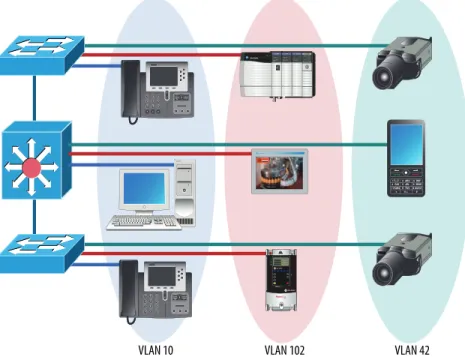
VLAN Trunking
Trunking enables a VLAN to span multiple switches.
VLANs and Segmentation Guidelines
Configure separate VLANs for different work cells or areas of your plant. Configure one VLAN for all data traffic relevant to one particular area or cell zone. Because 80…90% of traffic is local to one cell, this is the optimal design. All devices with multicast connections must be on the same VLAN. Within a VLAN, multicast and unicast traffic can be mixed depending on application requirements. The default communication type of unicast must be used for point-to-point communication to minimize device, network, and infrastructure loading:
• Design small cell or area zones, each with a dedicated VLAN and IP subnet.
• Restrict data flow out of the cell or area zone unless plantwide operations explicitly require it.
• Segment traffic types into VLANs and IP subnets to better manage the traffic and simplify security management.
• Within the cell or area zone, use Layer 2 VLAN trunking between switches with similar traffic types. When trunking, use 802.1Q, VTP in transparent mode.
• Use Layer 3 distribution switches to route information between cell or area Zone VLANs and plantwide operations in the Industrial Zone.
• Enable IP directed broadcast on cell or area zone VLANs with
EtherNet/IP traffic for easy configuration and maintenance from control systems, such as RSLinx® software.
• Avoid large Layer 2 networks to simplify network management.
• Select switches based on the VLAN features you need:
– Stratix 6000 switches support VLANs.
– Stratix 8000 and Stratix 8300 switches support VLANs and VLAN trunking, as well as Layer 3 switching (enables routing across VLANs and subnets). 802.1 Q Trunk VLAN 102 VLAN 42 VLAN 20 VLAN 102 VLAN 42 VLAN 20
Ethernet Infrastructure Features Chapter 3
Quality of Service (QoS)
Quality of service determines how packets are marked, classified, and treated based on traffic type. Rockwell Automation EtherNet/IP devices prioritize traffic internally. Implementing QoS at the switch level adds another level ofprioritization. QoS does not increase bandwidth—QoS gives preferential treatment to some network traffic at the expense of others.
Not all network traffic can be treated equally. To minimize application latency and jitter, control data must have priority within the cell or area zone. QoS gives preferential treatment to some network traffic at the expense of others. Control data is more sensitive to latency and jitter than information data.
To explain how QoS works, think about the last time you boarded a plane at the airport. As boarding time gets close, everyone starts to crowd around the gate. It is impossible for everyone to go down the jetway to the plane at once, so the airline establishes a boarding procedure to avoid chaos. This can be compared to the use of QoS on an Ethernet network. The network can have motion traffic, voice traffic, and email traffic all being transmitted at the same time over the network.
In the airline example, first class passengers board first, followed by families with small children, followed by frequent flyers, and followed by the coach cabin starting at the back of the plane. Similarly, QoS lets you set up priority queues in the managed switches on the network. In the automation example, equate motion traffic to the first class passengers and give it the highest priority for network usage. Voice traffic can go second (it also has low tolerance for delay), and email traffic has the lowest priority queue. This results in the least amount of delay possible on the motion control.
Ingress Actions Egress Actions
Classification Policing/Metering Marking Queue/ScheduleCongestion Control
Distinguish traffic by examining Layer 2/3/4 labels and QoS fields. QoS changed depending on trust state at port.
Make sure conformance is to a specified rate.
DSCP-CoS or CoS DSCP Mapping
4 queues/or with priority scheduling
QoS Guidelines
Follow these guidelines with QoS:
• Manage the output queues based on application needs. Schedule precision and motion control packets in the highest priority queue.
• QoS gives preferential treatment to Industrial Automation and Control System Network traffic at the expense of other network traffic.
• QoS is integrated into the Stratix 8000 and Stratix 8300 switch configurations.
• Deploy QoS consistently throughout Industrial Automation and Control System Network.
Resiliency
A resiliency protocol maintains parallel links for redundancy while avoidingloops. Network convergence time is a measure of how long it takes to detect a fault, find an alternate path, and recover from the fault:
• During the network convergence time, some portion of the traffic is dropped by the network because interconnectivity does not exist.
• Communication drops if the convergence time is longer than the Logix connection timeout.
Time Calculations in a Logix5000 System
Network convergence must occur before the control system is impacted:
• Logix message instruction (MSG) time out (explicit, CIP Class 3)
• I/O connection timeout (implicit, CIP Class 1), 4 x RPI, 100 ms minimum
• Logix Producer/Consumer connection timeout (implicit, CIP Class 1), 4 x RPI, 100 ms minimum
Ethernet Infrastructure Features Chapter 3
Resiliency Protocols
• Spanning Tree Protocol (STP), Rapid STP (RSTP), Multiple Instance STP (MSTP)
– Stratix 8000 and Stratix 8300–MSTP default
– Rapid Per VLAN Spanning Tree Plus (rPVST+); Cisco Technology
• Resilient Ethernet Protocol (REP); Cisco Technology
• EtherChannel Link Aggregation Control Protocol (LACP); IEEE
• Flex Links; Cisco Technology
• Device-level ring; topology option Resiliency Protocol Mixed Vendor Ring Redundant Star Network Convergence
> 250 ms Network Convergence > 70 ms Network Convergence > 1 ms STP X X X RSTP X X X MSTP X X X X PVST+ X X X REP X X EtherChannel X X X Flex Links X X X DLR X X X
Spanning Tree Protocol (STP) and Rapid STP (RSTP)
Spanning Tree Protocol (STP) prevents loops on the network that occur when there is more than one open path active at once on the network. The convergence rate can take up to 50 seconds.
Rapid Spanning Tree Protocol (RSTP) is designed for faster network
convergence and eliminates the forwarding delay on point-to-point links by using explicit handshaking protocol. The convergence rate is significantly faster than STP:
• Only standard protocol for network resiliency—IEEE 802.1D
• Built into Stratix 8000 and Stratix 8300 switches
• Requires redundant star or ring topology
• Provides alternate path in case of failures, avoiding loops
• Unmanaged switches do not support STP or RSTP, or any other resiliency protocol
Catalyst 3750 Switch Stack
Stratix 8000 Access Switches F = Forwarding B = Blocking B Distribution Switches F B F
Ethernet Infrastructure Features Chapter 3
EtherChannel Protocol
The EtherChannel protocol combines multiple physical switch ports into one logical connection to increase bandwidth through load balancing, as well as physical connection redundancy.
This protocol groups several physical Ethernet links to create one logical Ethernet link for the purpose of providing fault-tolerance and high-speed links between switches, routers, and servers. An EtherChannel can combine 2…8 active Fast Ethernet or Gigabit Ethernet ports:
• Link Aggregation Control Protocol (LACP) port aggregation—IEEE 802.3ad
• Built into Stratix 8000 and Stratix 8300 switches
• Requires a redundant star topology
• Provides resiliency between connected switches if a connection is broken Fault-tolerance is a key aspect of EtherChannel. If a link fails, the EtherChannel technology automatically redistributes traffic across the remaining links. This automatic recovery takes less than one second and is transparent to network applications and the end user. This makes it very resilient.
Distribution Switches
Catalyst 3750 Switch Stack
F F
F F
Stratix 8000 Access Switches
Flex Links Protocol
The Flex Links protocol provides link-level, physical redundancy in redundant star topologies. A pair of Layer 2 switch ports are configured to act as a backup to each other:
• Built into Stratix 8000 and Stratix 8300 switches
• Requires redundant star topology
• Active/standby port scheme
– Provides an alternate path in case of failures, avoiding loops
– No bandwidth aggregation
– Equal speed ports recommended
– Provides fast fail over for multicast traffic
Distribution Switches
Catalyst 3750 Switch Stack
A S S A
Stratix 8000 Access Switches
A = Active S = Standby
Ethernet Infrastructure Features Chapter 3
Resilient Ethernet Protocol (REP)
REP operates on chain of bridges called segments. A port is assigned to a unique segment. A segment can have up to two ports on a given bridge. REP is built in to Stratix 8000 and Stratix 8300 switches.
REP supports closed and open rings in various topologies:
• Redundant networks can be built with REP segments
• Only ring resiliency protocol applicable to both Industrial and IT applications
• Ring recovery time is less than 70 ms for both unicast and multicast traffic in fiber implementations
REP is a segment concept. A segment is a chain of bridges.
When all links are operational, a unique port blocks the traffic on the segment. If any failure occurs within the segment, the blocked port goes forwarding.
REP Segment Interface f2 rep segment 10 Interface f1 rep segment 10 Interface f1 rep segment 10 Interface f2 rep segment 10 g1/1 g1/2 g1/1 g1/2 g1/1 g1/2 g1/1 g1/2 g1/1 g1/2 REP Segment Interface g1/2
REP segment 10 REP segment 10Interface g1/1 Interface g1/2 REP segment 10
Interface g1/1 REP segment 10
Edge Port
g1/2 Block Traffic Edge Port
g1/2 Unblock Link Failure g1/1 g1/1 g1/1 g1/1 g1/1 g1/1 g1/1 g1/1 g1/1 g1/1 g1/2 g1/2 g1/2 g1/2 g1/2 g1/2 g1/2 g1/2 g1/2 g1/2
Segments can be wrapped into a ring. Identification of edge ports requires additional configuration.
Device-level Ring (DLR)
The DLR protocol is a layer 2 protocol that provides link-level, physical redundancy that provides network convergence in the 1…3 ms range for simple automation device networks. The other resiliency protocols apply to only infrastructure (switches and routers). DLR provides resiliency directly to an end device directly (such as an I/O module, drive, or controller).
Some control applications, such as safety and motion require network convergence times faster than what switch-oriented resiliency protocols can provide. Most control applications suffer connection timeouts with switch-oriented resiliency protocols.
Blocking Forwarding Forwarding A X Y B C A X Y B C Link Failure Blocking Forwarding X A B Y Forwarding Link Failure X A C C B Y
Ethernet Infrastructure Features Chapter 3
A DLR network is a single-fault tolerant network. Network traffic is managed to make sure critical data is delivered in a timely manner.
Physical layer failure includes the following:
• All faults that are detectable at physical layer
• Physical layer failure detected by protocol-aware node
• Status message sent by ring node and received by ring supervisor
Stratix 8000 IE Switch Beacon Beacon Forwarding ControlLogix Controller Active Ring Supervisor
Announce Blocking Announce
ETAP POINT I/O Distributed I/O ArmorPOINT I/O Distributed I/O POINT I/O Distributed I/O ArmorPOINT I/O Distributed I/O Stratix 8000 IE Switch ETAP ControlLogix Controller Active Ring Supervisor Link Failure Link Status Link Status POINT I/O Disrtributed I/O ArmorPOINT I/O Distributed I/O POINT I/O Disrtributed I/O ArmorPOINT I/O Distributed I/O