Modeling and Simulation of a Hybrid Fuzzy And
Hysteresis Current Controller for Single Phase Grid Attached PWM Inverter
for Melioration of Power Quality
B.SRIVENI
P.G. scholar, Dept of EEE
Trr College of Engineering & Technology,
Hyderabad, Telangana, India
Abstract
-
Advancements in power electronics has allowed a wide investigation towards DG systems the main abstruse is the harmonization of the DG to the utility grid. Generally current regulated PWM voltage-source inverters (VSI) are used for synchronizing the utility grid with DG source in order to meet the following objectives: 1) To ensure grid stability 2) active and reactive power control through voltage and frequency control 3) power quality improvement (i.e. harmonic elimination) etc. In this paper, power quality is being improved by diminishing current error at high band width so a hysteresis controller with fuzzy logic is being proposed. The present model is being compared with the conventional hysteresis model and is being simulated in the MATLAB.I. I
NTRODUCTIONWith increasing renewable energy resources DGs are the viable option as because it can provide a 1) secure and diversified energy options, 2) increase the generation and transmission efficiency, 3) reduce the emissions of greenhouse gases, and 4) improve the power quality and system stability. Inspite of the several advantages, the main technical challenge is the synchronization of the DGs with the utility grid However, the converter performance is largely depends on the applied current control strategy. Very extensive research work has been done besides current control techniques and is available in the literature. [2].
The common strategies of current controllers can be classified as ramp comparator, hysteresis controller, and predictive controller amongst which the hysteresis controllers are widely used because of their inherent simplicity and fast dynamic response [3]. The main objectives of the control of grid connected PWM-VSI is to 1) ensure grid stability 2) active and reactive power control through voltage and frequency control 3) power quality improvement (i.e. harmonic elimination) etc.
In this paper fuzzy with hysteresis controller is proposed to enhance the power quality by diminishing current error at higher band width. The studied system is modelled and simulated in the MATLAB/Simulink environment and the result obtained is compared with the conventional hysteresis controller.
II. S
INGLEP
HASEG
RID-C
ONNECTEDVSI
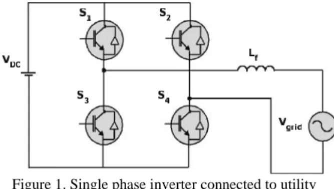
The figure 1 shows the The single-phase grid connected inverter the inverter consists of four switches (S1-S4), a filter inductor (Lf),dc source and utility grid (Vg). the produced voltage from inverter must be higher than the Vgin order to assure power flow to grid. Since Vgis uncontrollable, the only way of controlling the operation of the system is by controlling the current that is following into the grid.
Figure 1. Single phase inverter connected to utility grid
III. A
NALYSIS OFH
YSTERESIS ANDF
UZZYW
ITHH
YSTERESISC
URRENTC
ONTROLLERA. Hysteresis band current controller.
current error, sub-harmonic generation in the current and uneven switching [4].
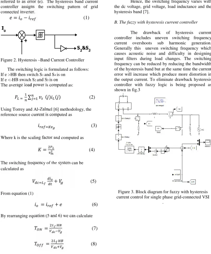
Hysteresis controller as shown in figure (2) the error is directly fed to the hysteresis band the reference line current of the grid connected inverter is referred to as iref and difference between ioand irefis referred to as error (e). The hysteresis band current controller assigns the switching pattern of grid connected inverter.
= −
(1)
Figure 2. Hysteresis–Band Current Controller
The switching logic is formulated as follows: If e >HB then switch S1and S4is on
If e <-HB switch S2and S3is on The average load power is computed as:
∑
( ) ( )
(2)
Using Torrey and Al-Zalmel [6] methodology, the reference source current is computed as
(3)
Where k is the scaling factor and computed as
=
(4)
The switching frequency of the system can be calculated as
+
(5)
From equation (1)
=
+
(6)
By rearranging equation (5 and 6) we can calculate
=
(7)
=
(8)
=
=
+
(9)
=
(10)
Hence, the switching frequency varies with the dc voltage, grid voltage, load inductance and the hysteresis band [7].
B. The fuzzy with hysteresis current controller
The drawback of hysteresis current controller includes uneven switching frequency current overshoots sub harmonic generation. Generally this uneven switching frequency which causes acoustic noise and difficulty in designing input filters during load changes. The switching frequency can be reduced by reducing the bandwidth of the hysteresis band but at the same time the current error will increase which produce more distortion in the output current. To eliminate drawback hysteresis controller with fuzzy logic is being proposed as shown in fig.3
Figure 3. Block diagram for fuzzy with hysteresis current control for single phase grid-connected VSI
FIG 4: The structure of fuzzy logic controller
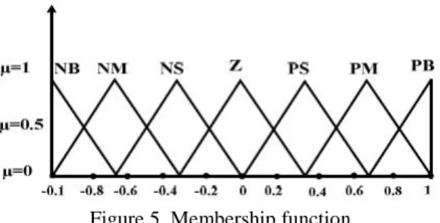
Here the membership function is chosen as triangular as shown in fig 5. The input is taken as error (e) and the change inerror (Δe) .Total 49 rules are taken into account as given in table -1.
Figure 5. Membership function
For example If e is negative medium (NM) and Δe is positive small (PS) Then output is negitive small (NS).
Table-1-Rule base for fuzzy controller
IV. R
ESULTS &D
ISCUSSIONThe section reveals the simulation results for fuzzy with hysteresis current control algorithm applied to single-phase mains connected inverter system and also the result is compared with conventional hysteresis controller on the basis of current error and harmonic distortion. The studied model has been developed and simulated in the MATLAB/simulink environment. For simulation, the Dc-link voltage is taken 400V, and the grid voltage is
240V, the inductance of the line is 5mH and the utility grid frequency is 50Hz.
A. Simulation results under steady state conditions
Figure 6. Simulation results of the fuzzy with hysteresis current controller for steady state (a) grid voltage (Vg) (b) reference current, actual current and
current error.
Figure 7. Response of parameters (a) Grid current and load curren (b) Active power & reactive power
Fig 7 shows that that the proposed controller is able to control the active and reactive power independently.
B. Simulation results during Transient conditions
1) Response with Step changes in the load
Figure 8. Simulation results of reference current, actual current and error for change in load with
hysteresis current controller
Figure 9(a) Simulation results of reference current, actual current and error for change in load with fuzzy
hysteresis current controller 9(b) Response of grid parameters load current and grid current 9(c)
Active power and reactive power.
Fig.9 shows the change in active power, load, current and grid current during the load transient which shows that the dynamic response faster of the proposed controller.
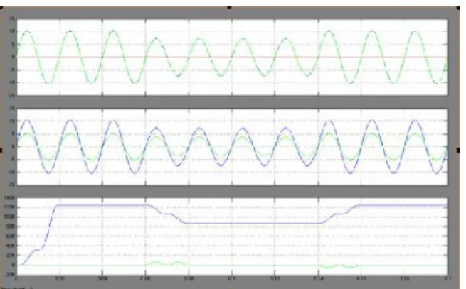
2) effect of changes in the hysteresis band width In this case the hysteresis band width is changed at time t= 0.1 sec from HB=1 to HB=3
(a)
(b)
Figure 10. Simulation result of grid current, error and switching frequency (a) for hysteresis controller (b)
fuzzy with hysteresis controller
As the band width of the hysteresis controller is creasing the switching frequency decreases but the current error increase so also the distortion in the grid current increases as shown in fig.10 (a). In the proposed controller even if the band width increases the distortion in grid current and change in error is very less as shown in fig 10(b), It implies that the switching frequency can be decreased without hampering the power quality
3) effect of phase changes in the grid voltage
In studied current control scheme the inverter is also able to inject the current in phase with the grid voltage.fig 11. (a) Shows that the current is in phase with the voltage even if the there is a phase change in the grid voltage at 0.1 sec. Fig 11. (b) Indicates the power factor of the grid current which is unity.
Figure 11. Simulation result of (a) grid voltage and inverter current frequency (b) power factor
Figure 12(b)THD of grid current with hysteresis fuzzy controller
Fuzzy with hysteresis current comptroller The THD of the proposed controller is considerably less 1.66% as shown in fig.13 as compared to conventional hysteresis controller which is found to be 2.30% as in fig.14.
V. C
ONCLUSIONSIn this paper hysteresis current controller with fuzzy logic is being applied to the single phase grid connected inverter and the power quality is being improved even with the reduced switching frequency and increased band width the current error is minimum compared to the conventional hysteresis controller. With the reduced switching frequency the switching losses are reduced and the reduction in THD is being observed.
R
EFERENCES[1] Yaosuo Xue; Liuchen Chang; Sren Baekhj Kjaer; Bordonau, J.; Shimizu, T.; , "Topologies of single-phase inverters for small distributed power generators: an overview," IEEE Transactions on Power Electronics, vol.19, no.5, pp. 1305- 1314, Sept. 2004.
[2] M.M.P.Kazmierkowaski, L.Malesani: “PWM Current Control Techniques of voltage source converters-A Survey” IEEE Trns. On Industrial Electronics,Vol.45, no.5, oct.1998.
[3] Blaabjerg, F.; Teodorescu, R.; Liserre, M.; Timbus, A.V., “Overview of Control and Grid Synchronization for Distributed Power Generation Systems” IEEE Transactions on Industrial Electronics, Vol.:53, Issue: 5,2006 , Page(s): 1398 – 1409.
[4] Ho, C.N.-M.,Cheung, V.S.P.,Chung, H.S.-H.” Constant-Frequency Hysteresis Current Control of Grid-Connected VSI without Bandwidth Control”,IEEE Trans. on Power Electronics, TPEL,2009 Volume: 24, no. 11 , 2009, Pp:2484 – 2495
[5] Hilloowala, R.M.; Sharaf, A.M.; "A rule-based fuzzy logic controller for a PWM inverter in a standalone wind energy conversion scheme," IEEE Trans. on Industrial Applications, vol.32, no.1, pp.57-65, Jan/Feb 1996
[6] D. Torrey and A. Al-Zamel, "Single-phase active power filters for multiple nonlinear loads," IEEE Transactions on Power Electronics, vol. 10, no. 3, pp. 263-272, May 1995.
[7] Krismadinata,Rahim N.A.,Selvaraj,J.,” Implementation of Hysteresis Current Control for Single-Phase Grid Connected Inverter” International. Conference on Power Electronics and Drive Systems, 2007. PEDS '07., pp: 1097–1101