Name: ______________________________________ Period: ____
Teacher: ____________________________________ Date: ______
Slinky Waves
Purpose
To generate, observe, and describe the different parts of transverse and longitudinal waves.
Introduction
Think for a moment about the various types of waves that you may have encountered in your lifetime—sound waves, light waves, radio waves, microwaves, water waves, earthquake waves, and so on. It is almost hard to believe that waves are traveling all around us. The majority of information we receive on a daily basis reaches us in the form of waves. Sometimes we can visibly see a wave and sometimes we cannot. But what is a wave? What are some common characteristics and properties shared by all of these different waves?
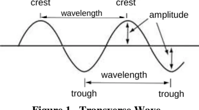
Waves are nature’s way of getting energy from point A to point B without changing the average location of any matter. A wave is commonly defined as a disturbance that travels through a medium or space. As a wave propagates (travels), energy is transferred through the medium or space. Waves are often categorized based on how they travel. A transverse wave has vibrations that are perpendicular to the direction of wave travel. Transverse waves display the common characteristic properties of wavelength, amplitude, and frequency (see Figures 1 and 3). A longitudinal wave, such as sound, has vibrations parallel to the direction of wave travel. Longitudinal waves display the characteristic properties of compressions and rarefactions (see Figure 4). A
standing wave is a wave pattern created by the interference of two identical waves traveling in opposite
directions. Standing waves are often set up in musical instruments, and display the characteristic properties of nodes and antinodes (see Figure 5).
crest crest
wavelength
Materials
: Slinky, Wave Demonstrator (1.8 meter helical spring)Lab Guidelines:
1. Place all belongings on the lab benches. You will be working with the slinky on the classroom tables. 2. You may stretch the slinky the long length of a single classroom table. Do not stretch it any further than
this or the slinky will permanently deform.
3. When moving the slinky back and forth on the table, the waves formed by the slinky must never go beyond the edge of the table.
4. Do not distort the slinky in any way that will result in permanent stretching, bending, or other deformation.
trough trough
wavelength
amplitude
Procedure
Producing a Transverse Wave
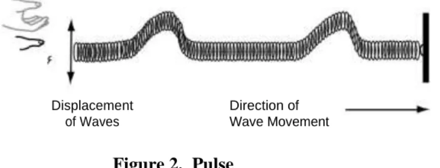
1. Have one classmate hold a few spirals of the end of the slinky. Stretch the slinky across the long length of a classroom table. Shake the free end of the spring up and down once. Observe the pulse move down the spring (see Figure 2). Notice that the amplitude of the wave decreases as it moves the length of the spring.
Displacement Direction of
of Waves Wave Movement
2. Now generate a train of transverse waves by shaking the spring back and forth, respectively, while keeping the amplitude the same. Transverse waves displace particles perpendicular to the direction of wave propagation (see Figure 3).
3. Draw a complete diagram of the transverse waves you just created in the box below. Label two crests and two troughs.
4. Next, increase the frequency by shaking the spring more rapidly while keeping the amplitude the same. Remember to keep the crests and troughs of your waves from going beyond the edge of the table.
WARNING:
BE CAREFUL NOT TO EXCEED THE ELASTIC LIMIT OF THE SLINKYOR ENTANGLE THE SLINKY WITH ITSELF OR OTHER SLINKYS.
Figure 2. Pulse
Figure 3. Transverse Wave
5. Draw a complete diagram of the transverse waves with higher frequency in the box below. Label one wavelength by showing where it begins and ends. Clearly label the amplitude of one of the
wavelengths.
Interference of Pulses
6. With two students holding a stretched slinky across a table, have one student (“student A”) produce a pulse by shaking the slinky towards the front of the classroom and back to the starting position once (do not go back and forth). Have “student B” produce a pulse by shaking the slinky on the same side of the table (towards the front of the room). Now have both students produce a pulse on the same side of the table at the same time. What happens to the pulses when they meet in the middle? Since the pulses were produced on the same side of the table, they should add together in the middle to momentarily create one larger wave. This is called constructive interference.
7. Draw a diagram of the constructive interference wave produced by the two pulses.
8. Now have students A produce a pulse towards the front of the classroom while student B produces an equally sized pulse towards the back of the classroom (in the opposite direction). Since the pulses were produced on opposite sides of the table, they should cancel each other out as they pass through each other. This is called destructive interference.
9. Draw a diagram of the destructive interference produced by the two pulses.
Transverse waves, higher frequency
Constructive interference
Producing a Longitudinal Wave
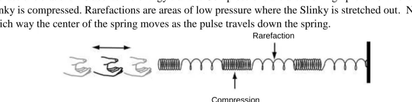
10. With a classmate holding one end of the slinky, hold the free end of the Slinky in one hand and stretch it across the table. Push the Slinky in and out as shown in Figure 5. Observe the compressions and
rarefactions that are created as the energy travels. Compressions are areas of high pressure where the Slinky is compressed. Rarefactions are areas of low pressure where the Slinky is stretched out. Note which way the center of the spring moves as the pulse travels down the spring.
Rarefaction
Compression
11. Draw a diagram of the longitudinal wave in the box below. Use arrows to indicate which way you vibrate a slinky to produce a longitudinal wave.
Producing a Standing Wave
12. Use the Transverse Wave Procedure to create a standing wave. A standing wave is a wave pattern that results when two waves of the same frequency, wavelength, and amplitude travel in opposite directions and interfere with each other. When a standing wave is created, you will see nodes and antinodes. A node is a point in a standing wave that appears to be stationary. This is due to complete destructive interference. An antinode is a point in a standing wave, halfway between two nodes, at which the largest amplitude occurs (see Figure 5).
13. If time allows, trade in your Slinky for a Wave Demonstrator (1.8 meter helical spring) with your teacher. Stretch the Wave Demonstrator a few meters with a classmate but maintain some sag in the middle. Without permanently distorting the spring, produce a standing wave with the Wave
Demonstrator. Note where the nodes and antinodes appear. Return the Wave Demonstrator to your teacher.
Figure 4. Longitudinal Wave
Longitudinal Wave
Figure 5. Standing Wave
antinode
Post-lab Problem
Draw a diagram of a standing wave in the box below. Label the following parts of the wave: 1. Wavelength
2. Amplitude 3. Crest 4. Trough 5. Node 6. Antinode