Sharif University of Technology
Scientia IranicaTransactions D: Computer Science & Engineering and Electrical Engineering www.scientiairanica.com
Current feedback op-amp based linear
voltage-controlled oscillator using analog multipliers
and minimum passive components
W. Jaikla
a;and A. Lahiri
ba. Department of Engineering Education, Faculty of Industrial Education, King Mongkut's Institute of Technology Ladkrabang, Bangkok, 10520, Thailand.
b. D3, Friends Apartment, IP Extension, Delhi, 110092, India.
Received 11 October 2014; received in revised form 20 July 2015; accepted 3 November 2015
KEYWORDS Voltage-controlled oscillator;
Single-resistance-controlled oscillator; Current-feedback op-amp;
Electronic tuning; Multiplier.
Abstract. This paper reports a new realization of linear Voltage-Controlled Oscillator (VCO) using three Current-Feedback Op-Amps (CFOAs), three analog multipliers, and only four passive components. Thus, minimum numbers of passive components are used to devise a canonic sinusoidal oscillator. The circuit provides non-interactive electronic tuning of both the Condition of Oscillation (CO) and the Frequency of Oscillation (FO) via the gains of two dierent analog multipliers. The impedance at output node exhibits low impedance which is easy to directly connect to load without any additional voltage buer. The proposed circuit has been simulated in SPICE using macro-model of AD844 CFOA ICs and AD633 multiplier ICs.
© 2016 Sharif University of Technology. All rights reserved.
1. Introduction
Single-Resistance-Controlled Oscillators (SRCOs) have been researched extensively using a variety of active devices in the recent past. Their popularity is mainly attributed to their independent tuning law for the Condition of Oscillation (CO) and the Frequency of Oscillation (FO). In the last decade, the SRCOs, using electronically controllable active devices like the Dierential Voltage Current Conveyor Transconduc-tance Amplier (DVCCTA) [1], the Dierential Volt-age Current-Controlled Conveyor Transconductance Amplier (DVCCCTA) [2], Current Controlled Cur-rent Dierencing Transconductance Ampliers (CC-CDTAs) [3,4], have been proposed. However, these active devices are not commercially available. Among *. Corresponding author. Tel.: +66 2329 8000;
Fax: +66 2329 8435
E-mail addresses: [email protected] (W. Jaikla); [email protected] (A. Lahiri)
the wide variety of active devices, by which SRCO realizations have been attempted, Current Feedback Op-Amps (CFOAs) remains as one of the most popular choices for the active device. This is because:
(i) CFOAs have many advantages over conventional op-amps, e.g. wide bandwidth independent of the close-loop gain, high slew-rate, and ease of realizing variety of circuit solutions using a reduced number of passive components [5];
(ii) of their commercial availability, e.g. AD844 [6], making them suitable for bread-board implemen-tations;
(iii) Some commercially available CFOAs, like AD844AN with an externally accessible high-output impedance compensation pin, have been found to be particularly attractive in creating current-mode circuits and particularly Explicit-Current-Output (ECO) oscillators [7-11].
literature [5,12-14]. The oscillator circuits in [5,12,13] use two CFOAs and ve passive components (three resistors and two capacitors) and the CO and FO are controllable via two dierent resistors. The CFOA-based sinusoidal oscillators in [14] are very excellent circuits. They employ three CFOAs and six passive elements (four resistors and two grounded capacitors). The independent control of both CO and FO through separate resistors is achieved. Also, the inuence of parasitic elements in CFOAs will not aect the CO during the FO tuning process. However, these circuits do not directly oer electronic control of either the CO or the FO, but the CO/FO controlling resistor may be replaced by MOSFET-based Voltage-Controlled Resis-tor (VCR) [15] to oer electronic control. Recently, a systematic technique of converting SRCO into VCO has been reported by Gupta et al. [16], wherein the frequency controlling resistor (in both grounded and oating forms) has been suitably replaced by FET-based VCR of [17]. The SRCOs, wherein grounded frequency controlling resistor was used, could be trans-formed into VCOs without requiring any additional CFOAs, but the resulting circuits required matched resistors to realize VCR and FO and were highly temperature dependent (e.g., due to the mobility factor of the employed MOSFET, being proportional to T 1:5). An alternate technique to realize VCO with
low temperature dependent FO is to use analog multi-plier(s) in the loop so that their multiplier gain terms appear in the CO and FO. In such a case, CO and FO will be independently controllable via the voltage gains of two dierent analog multipliers, which are ratio of two voltages. Several such realizations are available in the literature and their key features are briefed here:
a. The circuit in [18,19] uses three voltage-op amps, a large number of passive components (fourteen or more), and two or more analog multipliers in the feedback loop to realize VCO with independently controllable CO and FO by multiplier gains. The dependence of FO on the control voltage (Vc) for the
circuit in [18] is of the form FO being proportional to pVc, and for the circuit in [19] is FO being
proportional to Vc, i.e. linear VCO;
b. The circuits in [20] require very few components as compared to the previous circuits [18,19]. Employ-ing only one or two voltage op-amps, seven passive components, and two cascaded analog multipliers, the circuits could realize linear VCOs. However, the circuits require matched resistors to realize the Negative Impedance Convertor (NIC) and the CO does not have any electronic control. In addition, the last two oscillator circuits require CO control by capacitor as compared to the resistor in the rst two oscillator circuits;
c. The minimal component count linear VCOs in [21]
use only one CFOA, two cascaded analog multipli-ers, and ve passive components. As the circuits in [20], the circuits in [21] lack any electronic control for the CO and establish the CO control via capacitors.
In this paper, we propose a new linear VCO with minimum number of passive components (only four) as compared to any of the VCO circuits in [18-21] and with additional feature of independent electronic CO and FO tuning as compared to the linear VCO circuits in [20,21]. This additional feature is at the cost of increased number of active components, namely three CFOAs and three analog multipliers. However, it should be mentioned that this component count is still much less prevalent than linear VCO with independent electronic CO and FO tuning in [19]. The proposed circuit has been simulated in SPICE using advanced macro-model of AD844 CFOA ICs and AD534 multi-plier ICs and the results are in correspondence with the theory.
2. Proposed circuit
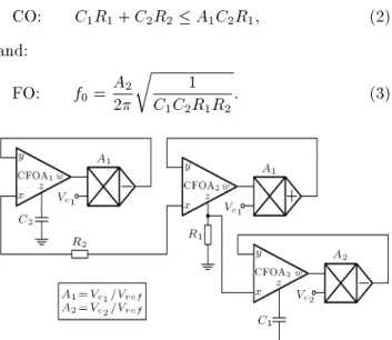
The proposed VCO circuit is shown in Figure 1. The proposed oscillator consists of three CFOAs, three ana-log voltage multipliers, two resistors, and two grounded capacitors. Assuming ideal CFOA and multiplier with no parasitic elements and using routine circuit analysis, we get the following characteristic equation:
s2C
1C2R1R2+ sA2(C1R1+ C2R2 A1C2R1)
+ A2
2= 0: (1)
Here, A1 and A2 are the gains of the rst and second
analog multipliers. From Eq. (1), the condition of oscillation and frequency of oscillation are written as:
CO: C1R1+ C2R2 A1C2R1; (2)
and:
FO: f0= A22
r 1
C1C2R1R2: (3)
It is evident from Eqs. (2) and (3) that the CO and FO can be independently controlled via the analog multiplier gains, A1 and A2, respectively. Also, since
FO is proportional to A2, the circuit is a linear VCO.
Now, considering the non-zero parasitic resistance Rx
at the x terminal of the CFOA, parasitic resistance Rz and parasitic capacitance Cz at the high-output
impedance z terminal of the CFOA, and external resistors R1, R2<< Rz(such a condition in most cases
is necessarily required to practically realize an oscillator with pseudo de-coupled CO and FO tuning laws [21]), we nd the modied FO as:
FO: f0 0=A22
s
R2
(C1+Cz)(C2+2Cz)R1(R2+Rx)2(4);
and: FO: f0
0 f0
1
C
z
2C1 +
Cz
C2 +
Rx
R2
: (5)
3. Simulation results
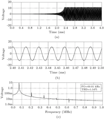
The proposed circuit was simulated in SPICE using advanced macro-model of the commercially available CFOA and analog multiplier ICs. AD844 was used as the CFOA IC and AD633 as the analog multiplier IC. The gain of AD633 analog multiplier is Vc=10 (Vref =
10 V) [22]. With voltage supplies of 16 V, passive component values of C1 = C2 = 1nF , R1 = 1 k,
and R2= 5 k, the CO was set with A1= 1:24 (Vc1=
12:4 V) and FO was set with A2= 1 (Vc2 = 10 V). With
these values, the ideal FO according to Eq. (3) would be 71.17 kHz, according to Eq. (4) should be 69.97 kHz (noting that for AD844, Rx = 50 , Cz = 4:5 pF)
and the observed frequency from simulations was 69.01 kHz. The starting and steady-state waveforms of the signal across the w terminal of the second CFOA and its frequency spectrum (magnitude) are shown in Figure 2(a), (b), and (c), respectively. The Total Harmonic Distortion (THD) is about 1.45%. Practi-cally, the THD value could be decreased by setting A1
close to (C1R1+ C2R2)=C2R1. Also, the Automatic
Gain Control (AGC) circuit can be used instead of A1.
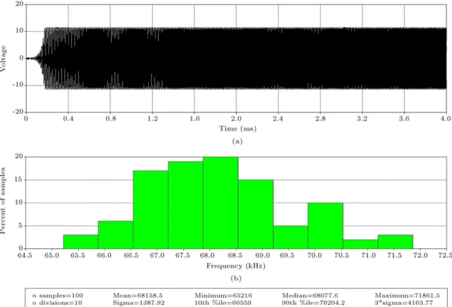
To investigate the stability of the proposed oscillator, the PSpice Monte-Carlo analysis with 5% Gaussian deviation on capacitors was used. In this study, 100 samples were run for verifying the oscillation frequency. The result is illustrated in Figure 3. It reveals that the proposed oscillator works well against capacitance tolerance.
4. Experimental results
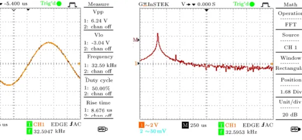
The working of the proposed oscillator was also veried using experimental results. With voltage supplies of
Figure 2. a) Start-up output voltage. b) Steady-state oscillation waveform. c) Frequency Spectrum.
16 V, passive component values of C1 = C2= 1 nF,
R1= 1 k, and R2= 5 k, the CO was set with A1=
1:228 (Vc1 = 12:28 V) and FO was set with A2 = 1
(Vc2 = 10). With these values, the ideal FO according
to Eq. (3) would be 71.17 kHz; however, the observed frequency from experiment was 62.92 kHz. The steady-state waveforms of the signal across the w terminal of the second CFOA and its frequency spectrum are shown in Figure 4(a) and (b), respectively. The output waveforms and their spectrums for Vc2 = 5 V, 8 V,
11 V, and 13 V are respectively illustrated in Figures 5, 6, 7, and 8. The variation of the FO with Vc2 is shown
in Figure 9. 5. Conclusions
We have proposed a new linear VCO, which although employs more active components than those of the linear VCO in [21], it provides independent electronic CO and FO tuning via the gains of the employed analog multipliers. As compared with the linear VCO in [19], which also has independent CO and FO tuning law, our circuit employs reduced number of active and passive components. In fact, our circuit employs minimum number of passive components as compared to any previous VCO in [18-21]. Simulation results using macro-model of commercially available ICs have proved the workability of the proposed circuit. The realizations of VCO with the same features as those in this circuit, but with reduced number of active
Figure 3. Monte-Carlo simulation of the proposed oscillator at 5% deviation of capacitance.
Figure 4. a) Oscillation waveform. b) Frequency spectrum.
components are a challenging problem which needs to be worked out.
Acknowledgements
The authors would like to thank the anonymous re-viewers for providing valuable comments which helped to improve the paper, substantially. The research described in this paper was nancially supported by King Mongkut's Institute of Technology Ladkrabang
(KMITL) and by National Research Council of Thai-land (NRCT), Grant No. A118-59-028.
Abbreviations
SRCO Single-Resistance-Controlled Oscillator;
CO Condition of Oscillation; FO Frequency of Oscillation;
Figure 5. a) Oscillation waveform. b) Frequency spectrum at Vc2= 5 V.
Figure 6. a) Oscillation waveform. b) Frequency spectrum at Vc2= 8 V.
Figure 8. a) Oscillation waveform. b) Frequency spectrum at Vc2= 13 V.
Figure 9. Variations of the frequency of oscillation with control voltage Vc2.
CFOAs Current Feedback Op-Amps; VCO Voltage-Controlled Oscillator; VCR Voltage-Controlled Resistor. References
1. Lahiri, A., Jaikla, W. and Siripruchyanun, M. \Voltage-mode quadrature sinusoidal oscillator with current tunable properties", Analog Integrated Circuits and Signal Processing, 65(2), pp. 321-325 (2010).
2. Jaikla, W., Siripruchyanun, M. and Lahiri, A. \Re-sistorless dual-mode quadrature sinusoidal oscillator using a single active building block", Microelectronics Journal, 42(1), pp. 135-140 (2011).
3. Jaikla, W. and Lahiri, A. \Resistor-less current-mode four-phase quadrature oscillator using CCCDTAs and grounded capacitors", AEU - International Journal of Electronics and Communications, 66, pp. 214-218 (2012).
4. Sakul, C., Jaikla, W. and Dejhan, K. \New resistor-less current-mode quadrature oscillators using 2 CC-CDTAs and grounded capacitors", Radioengineering, 20(4), pp. 890-897 (2011).
5. Senani, R. and Singh, V.K. \Novel single-resistance-controlled-oscillator conguration using current-feedback-ampliers", IEEE Transactions on Circuits and Syst. I, 43, pp. 698-700 (1996).
6. Analog Devices, Linear Products Data Book, Norwood, MA (1990).
7. Senani, R. and Sharma, R.K. \Explicit-current-output sinusoidal oscillators employing only a single current-feedback op-amp", IEICE Electronics Express, 2, pp. 14-18 (2005).
8. Gupta, S.S., Sharma, R.K., Bhaskar, D.R. and Senani, R. \Sinusoidal oscillators with explicit current output employing current-feedback op-amps", International Journal of Circuit Theory and Applications, 3, pp. 131-147 (2010).
9. Gupta, S.S., Sharma, R.K., Bhaskar, D.R. and Senani, R. \Synthesis of sinusoidal oscillators with explicit-current-output using current feedback Op-amps", WSEAS Transactions on Electronics, 3, pp. 385-388 (2006).
10. Lahiri, A., Jaikla, W. and Siripruchyanun, M. \Explicit-current-output second-order sinusoidal oscil-lators using two CFOAs and grounded capacitors", AEU- International Journal of Electronics and Com-munications, 65, pp. 669-672 (2010).
11. Lahiri, A., Jaikla, W. and Siripruchyanun, M. \First CFOA-based explicit-current-output quadrature sinu-soidal oscillators using grounded capacitors", Inter-national Journal of Electronics, 100(2), pp. 259-273 (2013).
12. Singh, V.K., Sharama, R.K., Singh, A.K., Bhaskar, D.R. and Senani, R. \Two new canonic single-CFOA oscillators with single resistor controls", IEEE Trans-actions on Circuits and Systems II, 52, pp. 860-864 (2005).
13. Gupta, S.S. and Senani, R. \State variable synthesis of single resistance controlled grounded capacitor oscilla-tors using only two CFOAs", IEE Proceedings Circuits, Devices and Systems, 145, pp. 135-138 (1998).
14. Bhaskar, D.R., Gupta, S.S., Senani, R. and Singh, A.K. \New CFOA-based sinusoidal oscillators retain-ing independent control of oscillation frequency even under the inuence of parasitic impedances", Analog Integrated Circuits and Signal Processing, 73, pp. 427-437 (2012).
15. Maundy, B., Gift, S. and Aronhime, P. \Practical voltage/current-controlled grounded resistor with dy-namic range extension", IET Circuits Devices and Systems, 2(2), pp. 201-206 (2008).
16. Gupta, S.S., Bhaskar, D.R. and Senani, R. \New voltage controlled oscillators using CFOAs", AEU-International Journal of Electronics and Communica-tions, 63(9), pp. 209-217 (2009).
17. Nay, K.W. and Budak, A. \A voltage-controlled-resistance with wide dynamic range and low distor-tion", IEEE Transactions on Circuits and Systems, CAS-30, pp. 770-722 (1983).
18. Singh, V.P. and Saha, S.K. \Voltage controlled oscil-lator with sine-wave output", IEEE Transactions on Instrumentation and Measurement, 37(1), pp. 151-153 (1988).
19. Saha, S.K. and Jain, L.C. \Linear voltage controlled oscillator", IEEE Transactions on Instrumentation and Measurement, 37(1), pp. 148-150 (1988).
20. Bhaskar, D.R. and Tripathi, M.P. \Realization of novel linear sinusoidal VCOs", Analog Integrated Circuits and Signal Processing, 24, pp. 263-267 (2000).
21. Bhaskar, D.R., Senani, R., Singh, A.K. and Gupta, S.S. \Two simple analog multipliers based linear VCOs using a single current feedback op-amp", Circuits and Systems, 1, pp. 1-4 (2010).
22. http://www.analog.com/media/en/technical-documentation/data-sheets/AD633.pdf Biographies
Winai Jaikla was born in Buriram, Thailand. He received the BSc degree in Telecommunication Engi-neering from King Mongkut's Institute of Technology
Ladkrabang (KMITL), Thailand, in 2002, MTech in Electrical Technology, and PhD in Electrical Education from King Mongkut's University of Technology North Bangkok (KMUTNB), Thailand, in 2004 and 2010, respectively. From 2004 to 2011 he was with Electric and Electronic Program, Faculty of Industrial Tech-nology, Suan Sunandha Rajabhat University, Bangkok, Thailand. He has been with the Department of En-gineering Education, Faculty of Industrial Education, King Mongkut's Institute of Technology Ladkrabang, Bangkok, Thailand, since 2012.
His research interests include electronic communi-cations, analog signal processing, and analog integrated circuits. He is a member of ECTI, Thailand. He is the author or coauthor of about 50 papers published in scientic journals or conference proceedings. He is an editorial board member of Far East Journal of Electronics and Communications.
Abhirup Lahiri received the BEng degree with the highest honors from the Division of Electronics and Communications, Netaji Subhas Institute of Technol-ogy (erstwhile, Delhi Institute of TechnolTechnol-ogy), Uni-versity of Delhi, India. He has been with STMicro-electronics since 2009, working in dierent IP groups in the eld of analog circuit design. In the past, he was responsible for the development of analog IPs like band-gap references, regulators, crystal oscillators, RC oscillators, LC oscillators, frequency-locked loops, and analog phase-locked loops. His past research works include design of compact analog circuit solutions using novel voltage-mode and current-mode active elements. His current research interests include low-power and low-voltage analog circuit design and precision voltage and current reference generation. He has authored/co-authored more than 30 international jour-nal/conference papers (including 15 SCI/SCI-E pub-lications) and has acted as a reviewer (by editor's invitation) for numerous international journals and conferences of repute. He served as a program com-mittee member for the 33rd International Conference on Telecommunications and Signal Processing (TSP). He is an editorial board member of Radioengineering Journal.