WHITE PAPER
Next Generation Intel® Xeon® Processors Tieto* Software Solutions
Networking and Telecom Industries
Introduction
Cloud computing is a broad term that covers everything from Google* applications to rack-based servers. In the enterprise space, it is driving improved data center efficiency, the result of sharing resources, like computing, networking and storage. At the heart of this approach is infrastructure convergence, which enables IT to more rapidly reallocate equipment to meet fluctuating and unpredictable business demand. At the same time, equipment utilization goes up, energy efficiency increases and support effort decreases. The current boom in network traffic, driven by mobile broadband and the deployment of over-the-top (OTT) services, accelerates the need for adoption of cloud concepts in the telecom network. This transition provides network operators opportunities to find new value-added services to cut into the OTT revenue stream. For example, implanting new, differentiating quality of service (QoS) features can open new market segments for service providers. Likewise, implementing IaaS (Infrastructure as a Service) solutions enables network
operators to capitalize on existing, under utilized equipment. Equally important is finding innovative ways to build a scalable and flexible network that cost efficiently handles an increasing data load by improving resource utilization.
Bringing cloud concepts to the telecom network enables business-to-business-based solutions to create end user value by aggregating multiple cloud services. For instance, integrating content caching into the telecom network can improve the quality of experience (QoE), as well as reduce the load on the network.
What does this then mean from a telecommunications point of view? Telecommunications has unique technical challenges when it comes to cloud implementation, including strict real-time requirements, packet latency and high availability. These requirements can be satisfied by next generation Intel® Xeon® processors, as demonstrated by a proof-of-concept developed by Intel and Tieto*. The platform enables a “communications cloud” designed to more efficiently use network resources and speed up functional and service deployments compared to today’s cloud platforms.
A single computing
architecture enables
cloud computing in
telecommunications
Developing a Wireless Communications
Cloud with Intel® Architecture
The foundation for this communications cloud is a single computing architecture capable of supporting all the software workloads in a core network. Put another way, it’s possible to have an entire evolved
packet core (MME, S-GW, P-GW, SGSN, HSS)1
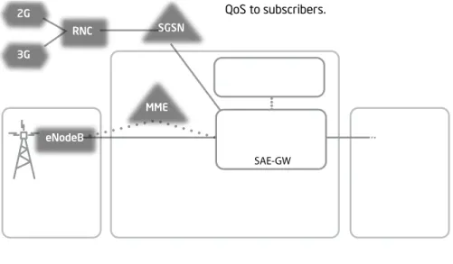
of an LTE network run on a single Intel® architecture processor platform (Figure 1). In addition, the platform’s resources are retargetable because they are defined in software, thus they can be redeployed quickly to best satisfy demand. This paper describes the implementation and capabilities of the EPC communications cloud proof-of-concept and presents benchmark data for packet throughput.
Communications Cloud Challenges
A communications cloud infrastructure enables network equipment to quickly respond to changing demand through improved load balancing, quick application migration and proactive power management. It satisfies the infrastructure needs of telecom service providers with a standardized “elastic network” that meets service quality requirements. As the equipment dynamically adapts to changing traffic conditions, it’s critical the network continues to meet service quality measures, including latency, packet loss and jitter, in order to deliver a high level of QoS to subscribers.
Figure 1. Network Core1 Running on an Intel® Architecture Processor-based Platform
For service providers with corporate clients, it may be necessary to offer service level agreements (SLAs). Meeting SLAs may require prioritization schemes (e.g., traffic shaping) used to establish traffic classification categories, as in Tier 1 or Tier 2 customers. The communications cloud must also comply with real-time specs, such as a guaranteed bitrate, defined in the 3GPP Technical Specification 23.107: Quality of Service (QoS) Concept and Architecture. With these and other challenges in mind, engineers at Intel and Tieto developed a communications cloud platform that enables service providers to speed up the development and deployment of innovative services, as needed, through mechanisms that dynamically reallocate computing and I/O resources.
Intel’s Workload Consolidation
Strategy
Today’s wireless and wireline infrastructure can be quite complex, partly due to the diversity of computing platforms used to build network elements. For instance, a rack typically contains various bladed network elements that use different processor architectures, as illustrated in Figure 2. Maintaining these network elements requires expertise across different hardware platforms, operating systems and unique vendor technologies. However, this need not be the case. A path forward is Intel’s 4:1 workload consolidation strategy, depicted in Figure 3, that enables service providers and TEMS
This next generation Intel®
architecture platform
is designed expressly
for communications
infrastructure applications
and complementary
cryptographic and data
compression workloads.
Internet eNodeB MME Cloud Based Services Cloud EPC AccessIntel® Architecture Processor-Based Platform RNC HSS PCRF S-GW P-GW SAE-GW SGSN 2G 3G
B
C
D
A
Figure 2. Today’s Service Provider Infrastructure Has Various Network Elements That Use Different Architectures
to consolidate various hardware platforms into one. This is achievable using the next generation Intel Xeon processor based on the Intel® microarchitecture codenamed Sandy Bridge. The platform components that will be offered provide the scalability to design low-end elements, such as wireless access and branch routers, as well as high-end equipment, including LTE core network elements that could deliver up to 160 million packets per second layer
3 packet forwarding performance.2 Key to
enabling the EPC cloud capability is Intel’s workload consolidation platform capability, supporting the various core network workloads on a single platform. This next generation Intel architecture platform is designed expressly for
communications infrastructure applications, and complementary cryptographic and data compression workloads. The workload acceleration capabilities, supported by hardware and software, are accessed via a unified set of industry-standard application programming interfaces (APIs), which provides consistent conventions and semantics across multiple accelerator implementations and future-proofs software investments. The platform also delivers exceptional packet processing performance by running performance-optimized libraries from the Intel® Data
Plane Development Kit (Intel® DPDK). Signal processing software development is enabled using Intel® Software Development Tools (see http://software.intel.com/en-us/ intel-sdp-home/ for more details).
Capabilities Facilitated By
Software-Defined Network Elements
There are several key tenants of enterprise cloud computing that set the stage for capabilities that open the door to opportunities in telecommunications. • Abstract resources enabling computing
and networking resources to be retargetable
• On-demand provisioning allowing the composition of the core network to be changed
• Straightforward scalability simplifying capacity expansion or reduction • Power management utilizing network
resources more efficiently
With respect to the communications cloud, these tenets are attainable with software-defined network elements that run the full complement of telecom-centric workloads, as is possible with Intel architecture-based platforms. Moreover, this approach, combined with standardized architecture, enables the rapid deployment of new services and simplifies the operation and maintenance (O&M) of the infrastructure. In addition, the following compelling communication network usage models can be realized, and Intel plans to demonstrate them on future updates to the EPC communications cloud proof-of-concept.
Granular Load Balancing
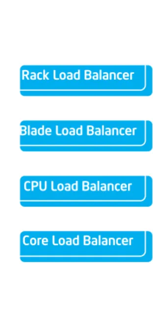
Distributing the workload across multiple network elements, referred to as load balancing, is an essential function to maximize resource utilization and minimize bottlenecks. With hardware-focused networks, load balancing is typically performed across similar or identical network elements. However, load balancing of software-defined network elements is more granular because
they are less physically constrained; the software can run on a processor core, on many cores, on an entire processor, a blade, a rack or even multiple racks, as depicted in Figure 4.
Benefit: Granular load balancing gives network operators greater control over platform resource utilization, which helps to make the communications cloud more productive.
Granular Power Control
When granular load balancing is
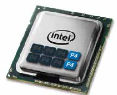
implemented, it is possible to significantly reduce power consumption during periods of low demand. This is accomplished by routing the workload to a subset of the available resources and powering down the rest. For example, peak traffic periods may require eight processor cores, whereas low traffic periods may only warrant two cores; thus six cores can be powered down. When this power control mechanism is implemented across a cabinet, energy consumption during off-peak times can be reduced by hundreds of watts, or greater. Power control can also be implemented at other levels: processor, blade and rack.
Benefit: Granular power control enables network operators to substantially reduce energy consumption without sacrificing service quality.
Intel®
Architecture
Applications & Services Control Plane Processing Packet Processing Signal ProcessingFigure 3. Intel’s 4:1 Workload Consolidation Strategy
Figure 4. Load Balancer Functions Across Different Architectural Levels
Site Load Balancer
Rack Load Balancer
Blade Load Balancer
CPU Load Balancer
Core Load Balancer
Live Application Migration
The application workload within the system can be re-assigned among the physical entities (e.g., processor core, blades or racks) in the system.
Benefit: During periods of low demand, it’s possible to conserve energy by moving live calls and data connections so they run on fewer blades, which makes it possible to power down the unused blades.
Multi-Standard
Conceptually, a communications cloud will concurrently support multiple types of core networks (2G, 3G, 4G, fixed), as depicted in Figure 6.
Benefit: Network operators can reduce capital expenditure and equipment support cost by deploying a single platform that implements all the network standards they support in a given location.
Multi-Tenancy
Similar to the multi-standard usage model, the communications cloud can support multiple instances of the same core network, enabling a common infrastructure to concurrently host several service providers (i.e., tenants), as illustrated in Figure 7. The ability to share core network infrastructure can significantly reduce time-to-market for service providers using the cloud and provide the framework for infrastructure sharing and virtual operator provisioning (SLA enforcement).
Benefit: Sharing hardware infrastructure across multiple operators reduces capital and operating expenses (CapEx/OpEx).
Network Reconfiguration
At any time, a computing resource in the communications cloud can be reconfigured to run any software associated with another software-defined network element. This enables the cloud to accommodate fluctuating service patterns, as in high demand for VoIP services during the day and for transcoding services in the evening when people like to download videos.
Benefit: Network operators can better adjust to changing demand by changing the mix of network elements and/or services, as in an explosive increase in traffic in a very small physical area. Another example is an unforeseen catastrophic event (e.g., earthquake) that damages existing network infrastructure, where network reconfiguration enables network operators to quickly replicate the core network in another location and restore services.
Communications Cloud
Proof-of-Concept
For the first phase of the previously described program, engineers at Intel and Tieto developed a communications cloud proof-of-concept to benchmark performance and demonstrate the load balancing capabilities of a next generation communications platform from Intel. A platform description is provided in Appendix A, and performance details are discussed in the following.
Figure 5. Intel Processor With Six of Eight Cores Powered Down (i.e., P4 Low Power State)
Communications Cloud Supports Multi-Standards
Intel® Architecture Processor-Based Platform HLR/VLR MSC HSS Base Station eNodeB 3G Network 4G Network PCRF GGSN SGSN P-GW S-GW RNC MME S-GW
Figure 6. A Communications Cloud Supporting Both EPC and 3G Networks Concurrently
Figure 7. A Communications Cloud Supporting Multiple Tenants
Communications Cloud Supports Multiple Tenants
Intel® Architecture Processor-Based Platform P-GW S-GW MME P-GW Service Provider 2 Service Provider 1 S-GW MME
ABouT TIETo*
Tieto* is a world-leading Network R&D service provider. Tieto has deep understanding of the nature of telecom systems built up over decades working closely with major equipment and service providers. This telecom network know-how, combined with our long IT managed services experience where cloud has been a reality for a long time, gives Tieto a unique ability to support our customers taking the communications cloud from hype to business reality.
For over 20 years, Tieto has delivered telecom R&D services to our satisfied customers. Tieto has over 6,000 experts working for leading network equipment providers, mobile device manufacturers, telecom operators and media companies.
For more information about Tieto, visit http://www.tieto.com/what-we-offer/ rd-services.
Single Cor
e Utilization
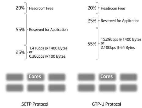
Intel® Xeon® Processor
SCTP Protocol
Headroom Free
Reserved for Application
1.41Gbps @ 1400 Bytes or 0.38Gbps @ 100 Bytes
Cores
20% 55% 25%Single Cor
e Utilization
Intel® Xeon® Processor
GTP-U Protocol
Headroom Free Reserved for Application
15.29Gbps @ 1400 Bytes or 2.10Gbps @ 64 Bytes
Cores
20% 55% 25%Control and user Plane Performance
Intel performance was measured using a single blade to simultaneously execute S-GW and MME workloads – two key network elements of an Evolved Packet Core (EPC). The primary workloads for an S-GW and an MME are user plane (i.e., packet processing) and control plane (i.e., signaling), respectively. The proof-of-concept runs representative implementations of S-GW and MME protocols, including SCTP and GTP-U. The application code executes in Linux* User Space using a Telecoms grade Linux User Space IP stack. The testing simulated multiple subscribers opening a data connection in a phone to create 80 percent utilization of a single processor core; the other five cores were unused during the testing. When simulating an MME network element, the core handled over 1.4 gigabits per second (Gbps) of traffic throughput (1,400 byte packets) while consuming 25% of its available CPU cycles.
The remaining 75% of the core could be used for applications (MME procedures) or other purposes. When the processor core performed an S-GW function, it delivered over 15 Gbps (1,400 byte
packets) throughput at 55% core utilization, leaving 45% for applications (S1AP) and auxiliary functions. This performance scales with the number of processor cores. The significant portion of the performance optimization was achieved by using elements from the Intel DPDK, including Linux User Space “Poll Mode” Ethernet drivers, zero buffer copy techniques, advanced cache utilization and dramatically reduced context switching.
Energy Efficiency
In this proof-of-concept, unused processor cores are placed into a low power state in order to save energy. In future proof-of-concept demonstrations, the load balance will be extended to manage the traffic across blades and shelves, along with the energy savings from powering them off when the traffic load warrants.
Live Workload Migration
The current proof-of-concept balances the load within a blade, and future versions will demonstrate load balancing among blades, racks and systems in different locations when an Intel processor-based platform is available. Dynamic load
migration also facilitates failover, whether moving the workload from a failed blade to another blade or quickly migrating a core network to a new location in the event of a natural disaster.
In-Service Performance and Network upgrade
A future version of the proof-of-concept will show how having access to a larger pool of common network resources can simplify and accelerate fault recovery (e.g., standby blade or software image) and system upgrades, as in adding more network functionality or capacity.
Load Balancing Capabilities
The proof-of-concept configuration (i.e., S-GW and MME) in the prior example was extended to include an HSS, Packet Data Network Gateway (P-GW) and a load balancer. The load balancer is the main controller of the cloud functionality, and its responsibilities include:
• Maintaining the system level state; this includes information regarding available cores, blades and elements, and the loads they execute.
• Making load balancing decisions based on the predefined triggers.
• Providing storage for runtime and configuration data.
Scenario 1: S-GW load balancing – load increases
The proof-of-concept has a graphical user interface (GUI) that can increase the number of active subscribers, which consequently increases the number of users either participating in a live call or streaming video. When the load reaches a certain level, the load balancer will take action, the first of which is adding CPU capacity to the S-GW. When the load crosses over the next threshold, the load balancer launches a second S-GW and distributes the traffic among the two instances.
For more information about software solutions from Tieto, visit
www.tieto.com
For more information about Intel solutions for communications, visit
www.intel.com/go/commsinfrastructure
Scenario 2: S-GW load balancing – loaddecreases
After the traffic load initiates the addition of a second S-GW, the number of subscribers is decreased via the GUI. First, the load balancer routes all the traffic to the primary S-GW and then takes actions to release the second S-GW and its associated resources. When load decreases below the next threshold, the load balancer reduces the CPU capacity of the primary S-GW, and any idle core is transitioned to a low-power state.
Scenario 3: EPC load balancing – load increases and then decreases The GUI increases and decreases
subscribers, and there is an impact on both user and control plane traffic. Likewise, the load balancer adjusts the CPU resource available to both the S-GW and the MME and adds/removes the second S-GW and MME instances according to the traffic load.
The Proof-of-Concept
- Moving Forward
The capabilities of the communications cloud proof-of-concept described in this paper represent about 30 percent of the target functionality, and work is ongoing to achieve the remaining objectives. Other enhancements include the use of virtualization environments, live workload migration and broader energy management.
Cloud computing in Telecom
The telecommunications industry faces difficult challenges driven by exploding growth in connections and data traffic that is devouring spare network
bandwidth. The upswing in data traffic is fueled by many factors, including mobile broadband and the deployment of over-the-top (OTT) services. At the same time, new revenue-generating opportunities are emerging, like IaaS (Infrastructure
as a Service), where network operators host service providers on underutilized or over-provisioned equipment that is re-purposed to support new business services. Business-to-business integration is also spawning profitable new services, such as content caching.
This is made easier with a flexible
infrastructure that helps service providers deliver the expected level of performance by giving them more control over how computing resources are allocated to workloads. The communications cloud proof-of-concept presented in this paper shows how this can be achieved through consolidation, load balancing and live load migration, while conserving as much energy as possible.
1 Abbreviations:
3GPP: 3rd Generation Partnership Project
eNobeB: refers to the LTE air interface and radio resource management GTP-U: GPRS Tunnelling Protocol User Plane
HSS: Home Subscriber Server MME: Mobility Management Entity PCRF: Policy and Charging Rules Function P-GW: Packet Data Network Gateway RNC: Radio Network Controller SCTP: Stream Control Transmission Protocol SGSN: Serving GPRS Support Node S-GW: Serving Gateway V-GW: Virtual Gateway
2 Results have been estimated based on internal Intel analysis and are provided for informational purposes only. Any difference in system hardware or software design or configuration may affect actual performance.
3 Performance tests and ratings are measured using specific computer systems and/or components and reflect the approximate performance of Intel products as measured by those tests. Any difference in system hardware or software design or configuration may affect actual performance. Buyers should consult other sources of information to evaluate the performance of systems or components they are considering purchasing. For more information on performance tests and on the performance of Intel products, visit http://www.intel. com/performance/resources/limits.htm
4 Benchmarks represent the high speed protocols used by the SGW and MME. Headroom is reserved for the MME and SGW node applications, which includes upper layer protocols. An additional 20 percent performance headroom is included for application growth and the addition of future features. The performance was measured on a single processor core, while the other cores were unused. Intel® Hyper-Threading Technology (Intel® HT Technology)5 was HT disabled.
5 Intel Hyper-Threading Technology (Intel® HT Technology) requires a computer system with an Intel® processor supporting Hyper-Threading Technology and an Intel® HT Technology enabled chipset, BIOS and operating system. Performance will vary depending on the specific hardware and software you use. For more information, see http://www.intel.com/content/ www/us/en/architecture-and-technology/hyper-threading/hyper-threading-technology.html; including details on which processors support Intel HT Technology.
Copyright © 2012 Intel Corporation. All rights reserved. Intel, the Intel logo and Xeon are trademarks of Intel Corporation in the United States and/or other countries.
*Other names and brands may be claimed as the property of others. Printed in USA 0212/MS/SD/PDF Please Recycle 326847-001US Appendix A: Platform Description
Intel Processor Next generation Intel processors are based on the Sandy Bridge microarchitecture Intel Chipset Intel chipset
System Memory 16G RAM DDR3-1333 MHz Operating System Wind River* Linux* 4.0
Ethernet NICs Intel® 82599ES 10 Gigabit Ethernet Controller with dual port optical interfaces Networking software Intel® Data Plane Development Kit (Intel® DPDK) R1.1
Networking software Carrier Grade Tieto* IP Stack (TIP) Networking software The OpenEPC* toolkit from Fraunhofer FOKUS*