TECHNICAL UNIVERSITY OF CLUJ-NAPOCA
ACTA TECHNICA NAPOCENSIS
Series: Applied Mathematics, Mechanics, and Engineering Vol. 62, Issue I, March, 2019
CONTROL AND ACTUATION SYSTEM OF A SIX DEGREES OF
FREEDOM ROBOTIC ARM
Florin COVACIU
Abstract: The paper presents the control and actuation of a robotic arm. This robotic system has six degrees of freedom. A gripper is attached on the robotic system, being able to grip different objects. The robot is controlled through a user interface, the robot motors can be individually and synchronously actuated. Key words: robotic arm, control, actuation, gripper, user interface, experimental model
1. INTRODUCTION
Depending on the given task, robot manipulators exhibit diverse forms and structures. In industrial sites the most frequently manipulators are those with 6 DOF, that can perform several individual jobs. Based on the required performance and work the robot manipulators are designed, for certain parameters, such as the joint structure and the length/weight of the link. An important aspect of robot design is identifying those parameters that affect robot performance [1, 2]. To increase the robot performance a key component is robot control where a lot of development is made. To meet the requirements on higher performance, model-based control is a key technology in the control of industrial robots where models and control schemes are continuously refined [3]. Industrial robots in nowadays, are increasingly used in modern and automated production processes and can perform tasks during many hours per day without getting tired or losing precision or effectiveness [4]. To build a robot, we need knowledge from the following areas: mechanical engineering, computer science, electrical engineering, mathematics, systems and industrial engineering. Robots are very used in industrial automation, they had revolutionized the industrial process of manufacturing [5]. The paper is organized as follow: Section 2 presents description of the real model of the
robotic arm. Section 3 presents the control and actuation system continuing with the user interface in section 4, followed by conclusions and references.
2. THE EXPERIMENTAL MODEL OF THE ROBOTIC ARM
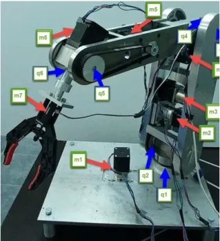
The experimental model of the robotic arm has been developed (see figure 1).
The motion of the robot is achieved using six actuators (m1, m2, m3, m4, m5, m6), which are
stepper motors, that actuate rotational joints. A DC motor (m7) is used to actuate the gripper. For the robot arm to rotate around the base (figure 1, q1) in clockwise and anti-clockwise direction a transmission belt pulley and toothed wheel (figure 2, 1) which rotates with the help of motor m1 (figure 1) has been used. In achieving high performance of any mechanical structure, an important role is assigned to the transmission elements that make the connections between the mechanical system components [6].
Fig. 2 Transmission belt pulley toothed wheel
To rotate the joint q2 (figure 1), a transmission belt pulley toothed wheel is used (figure 3, 2) which is actuated by a transmission belt actuated of the motor m2 (figure 1).
Fig. 3 Transmission belt pulley toothed wheel
To rotate the coupling q3 (figure 1) in the vertical plane, a transmission belt pulley toothed wheel is used (figure 4, 3) which is actuated by the motor m3 (figure 1).
Fig. 4 Transmission belt pulley toothed wheel
To rotate the coupling q4 (figure 1) in clockwise and anti-clockwise direction we used a transmission belt pulley toothed wheel (figure 5, 4) which rotates with the help of motor m4 (figure 1).
Fig. 5 Transmission belt pulley toothed wheel
Couple q5 (figure 1) of the robotic arm is rotated in vertical plane with the help of a transmission belt pulley toothed wheel (figure 6, 5) which is actuated by the motor m5 (figure 1).
3. THE CONTROL AND ACTUATION SYSTEM
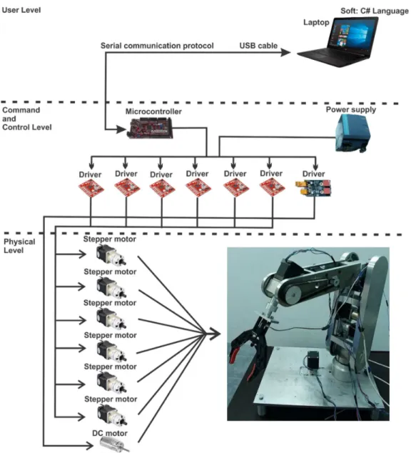
A schematic representation of the robotic arm control and actuation system is presented in figure 7.
The control system of the robotic arm is structure on three levels as following:
User Level;
Command and Control Level;
Physical Level.
Fig. 7 The control system of the robotic arm
User Level: include a laptop with Visual Studio C# programming environment. User interface
has been created in this programming environment, presented in figure 7.
Via the serial communication protocol, the communication between laptop and microcontroller has been created.
Command and Control Level contains:
• microcontroller board;
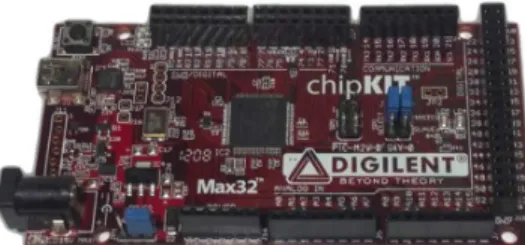
- The development board with microcontroller is called chipKIT Max32 (figure 8) from Digilent. The Max32 is a prototyping platform that adds the performance of the Microchip PIC32 microcontroller. The Max32 features a USB serial port interface for connection to the IDE and can be powered via USB or an external power supply.
The Max32 board takes advantage of the powerful PIC32MX795F512 microcontroller, which features a 32-bit MIPS processor core running at 80 MHz, 512K of flash program memory and 128K of SRAM data memory. In addition, the processor provides a USB 2 OTG controller, 10/100 Ethernet MAC and dual CAN controllers that can be accessed via add-on I/O shields.
The Max32 can be programmed using Multi-Platform IDE (MPIDE). In addition, the Max32 is fully compatible with the advanced Microchip MPLAB IDE and PICKit3 in-system programmer/debugger. It has 83 digital input/output pins, 16 analog inputs, 4 UARTs (hardware serial ports), 2 CAN controller. The motors program is loaded on the microcontroller. This program is written in the programming environment called MPLAB, in AnsiC and Arduino programming language. Arduino is an open-source software (IDE) which makes it easy to write code and upload to the development board. The environment is written in Java and based on Processing and another open-source software. Open source software can be used for commercial purpose, because commercial is not the same as proprietary, as they are based on different rules [7].
Fig. 8 Development board - chipKIT Max32
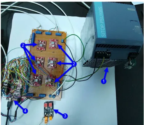
- For the stepper motor “Big Easy driver” (figure 9) has been used. This stepper motor driver was designed by Brian Schmalz. Each Big Easy Driver can drive up to a max of 2A per phase. It can take a maximum motor drive voltage of around 30V, includes on-board 5V/3.3V regulation, and a power supply is necessary for this stepper driver.
Fig. 9 Stepper motor driver
- For the DC motor “ME Dual DC Motor Driver” (figure 10) has been used. This DC motor driver It has 2 on board RJ25 ports, with which we can control 2 different DC motors at a constant current of 1A.
Fig. 10 DC motor driver
Fig. 11 Physical structure of the control system
The last level, Physical Level contains three main parts:
- The bipolar stepper motors:
• Nema 17 5:1 Stepper motor (figure 12, a)
Step Angle: 0.35 deg.; Rated current/phase: 1.68 A; Voltage: 2.8V;
Gear ratio: 5.18:1;
Max.Permisible Torque: 2Nm; Shaft maximum axial load: 50N; Shaft maximum radial load: 100N.
• Nema 17 27:1 Stepper motor (figure 12, b)
Step Angle: 0.067 deg.; Rated current/phase: 1.68 A; Voltage: 2.8V;
Gear ratio: 26.85:1;
Max.Permisible Torque:3Nm; Shaft maximum axial load: 50N; Shaft maximum radial load: 100N.
- DC motor (figure 12, c)
• Motor diameter: 8.5mm; Motor length: 20mm; Output shaft: 1.0mm; Shaft length: 5mm;
Voltage: 3V - 5V; Current: 1.5A;
a) b)
c)
Fig. 12 Components of the control and actuation system
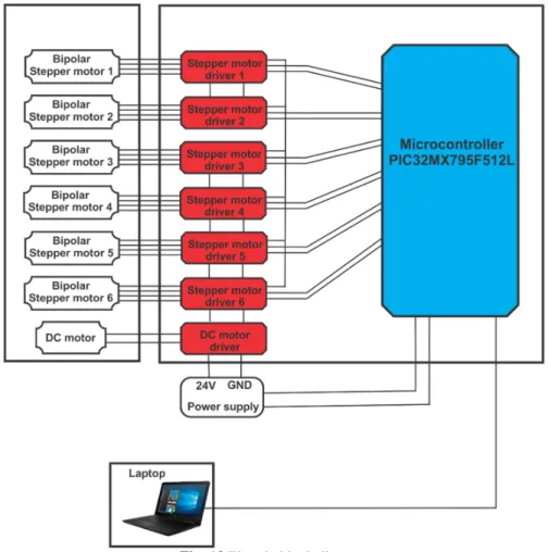
The electric block diagram of the robotic arm is presented in figure 13.
Fig. 13 Electric block diagram
4. USER INTERFACE
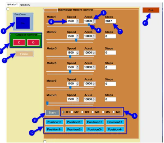
A simple user interface (figure 14) using well defined virtual buttons has been developed in order to be able to interact with the robotic arm. Behind the user interface for control of the robot the kinematics model was been implemented. The kinematics model for a serial robot, is an important task. According to dedicated literature, there are multiple methods to establish the expressions that modeling the
kinematic behavior for any mechanical structure [8].
The user interface has the following elements: 1. The connection between microcontroller
and laptop: if this button is on it means that the connection between the microcontroller and the laptop is on; 2. Command buttons for gripper: the close
gripper button - if this button is pressed,
the gripper will close. The open gripper button - if this button is pressed, the gripper will open;
3. Home button: performs the initialization of the motors position of the robotic system, by defining the zero point; 4. Slider: with this slider will increment and
decrement the number of steps;
5. The speed setting for the stepper motor; 6. The acceleration setting for the stepper
motor;
7. Number of steps;
8. Selecting the stepper motors;
9. After the stepper motors have been selected, we must press this button; 10.By pressing these buttons, the robot will
Fig. 14 User interface
A representation of the block software diagram is presented in figure 15.
This diagram is divided into two control system levels:
• Laptop level, on this level are the user interface and controls the commands;
• Microcontroller level contains the software part for the hardware components, the motor stepper drivers and control unit with chipKIT Max32 microcontroller from Digilent.
5. CONCLUSIONS
The paper presents the control and actuation system of a robotic arm with six degree of freedom. The robot has attached a gripper to it with which it can grip a wide variety of objects. A detailed presentation of the user interface is also showed in the paper, as part of the control system. The system performances have been validated by performing laboratory tests.
6. REFERENCES
[1] Liu, X., J., Wang, G, Performance atlases and optimum design of planar 5R symmetrical parallel mechanisms, Mechanism and Machine Theory, Volume 41, Issue 2, February 2006, Pages 119-144.
[2] Rout, B., Mittal, R., Screening of Factors Influencing the Performance of Manipulator using Combined Array Design of Experiment Approach, Robotics and Computer-Integrated Manufacturing, Vol. 25, No. 3, pp. 651-666, 2009.
[3] Torgny, B., Present and future robot control development - An industrial perspective, Elsevier, Annual Reviews in Control, Volume 31 (2007) pages: 69–79
[4] Gómez, A., P, Lafuente., Design and construction of a didactic 3-dof parallel links robot station with a 1-dof gripper. Journal of Applied Research and
Technology, Volume 12(3) (2014), pages: 435–443.
[5] Bizubac, D., Popa, M., Hörmann, B., Faur, A., Research of industrial processes in automation, Acta Tehnica Napocensis, Series: Applied Mathematics and Mechanics, vol. 61, Issue II, ISSN 1221-5872, pag. 253-660, 2018, Cluj-Napoca, România,
[6] Schonstein, C., Negrean I., Dynamics control functions for a ball screw transmission axis, Acta Tehnica Napocensis, Series: Applied Mathematics and Mechanics, vol. 60, Issue IV, ISSN 1221-5872, pag. 253-660, 2017, Cluj-Napoca, România,
[7] Timoftei, S., Brad, E., Sarb, A., Stan, O., Open-source software in robotics, Acta Tehnica Napocensis, Series: Applied Mathematics and Mechanics, vol. 61, Issue III, ISSN 1221-5872, pag. 519-626, 2018, Cluj-Napoca, România
[8] Schonstein, C., Kinematic control functions for a serial robot structure based on the time derivative jacobian matrix, Acta Tehnica Napocensis, Series: Applied Mathematics and Mechanics, vol. 61, Issue II, ISSN 1221-5872, pag. 253-660, 2018, Cluj-Napoca, România
[9] Torgny, B., Present and future robot control development- An industrial perspective, Elsevier, Annual Reviews in Control, Volume 31 (2007) pages: 69–79.
SISTEMUL DE CONTROL ȘI ACŢIONARE A UNUI BRAŢ ROBOTIC CU ŞASE GRADE DE LIBERTATE
Rezumat: Lucrarea prezintă controlul şi acţionarea unui brat robotic. Acest sistem robotic are şase grade de libertate. Pe sistemul robotic este atasat un griper cu care se pot prinde diferite obiecte. Robotul se controlează prin intermediul unei interfețe utilizator, iar motoarele robotului putând fi acţionate individual. De asemenea pentru deplasări complexe se dau traiectorii stabilite sistemului robotic pentru a face diferite sarcini.