AEI RAIL & ROAD MANAGER
User Manual
August 31, 2012
Copyright 2005 Softrail All rights reserved
AEI Rail & Road Manager
Softrail
1098 Venetia Road
Eighty-Four, PA 15330
Tel. 888 872-4612 (toll free US and Canada only)
Tel. 724 942-1473
Fax. 724 942-1480
E-mail [email protected]
Web Page www.aeitag.com
AEI Rail & Road Manager
Table of Contents
1. INSTALLATION ... 1
1.1. Installing AEI Rail &Road Manager ...1
1.2. Starting the Program ...1
2. BRIEF OVERVIEW... 1
3. OPTIONS ... 2
3.1. Information About Program Options & Vehicle Limits ...2
4. TECHNICAL SUPPORT AND UPDATES ... 3
5. TERMINAL DISPLAY ... 4
5.1. Vehicle Database and Terminal Layout Files...4
5.2. Moving a Vehicle...4
5.3. Moving Multiple Vehicles ...5
5.4. Moving Around the Terminal Display...6
5.5. Information Displayed by the Track/Road Name ...6
5.6. Zoom in and Zoom out ...6
5.7. Vehicle Justification...7
6. VEHICLE INFORMATION DISPLAY ... 8
6.1. General Vehicle Information Display...8
6.2. EDI 418 Data Display ... 11
6.3. UMLER/TAG Data Display... 12
6.4. Movement History... 13
7. USER DEFINED FIELDS... 14
8. USER DEFINED VEHICLE COLORS... 16
9. USER DEFINED STATUS LINE ... 17
10. ADD, DELETE OR FIND A VEHICLE... 18
10.1. Manually Adding a Vehicle ... 18
10.2. Manually Deleting a Vehicle ... 18
10.3. Automatic Vehicle Deletion ... 19
10.4. Finding a Vehicle... 19
10.5. Automatic Deletion of Vehicles ... 19
11. VEHICLE LIST DISPLAY... 20
11.1. Vehicle List Search Criteria... 20
11.2. Vehicle List Display... 23
11.3. Column Widths... 23
11.4. Column Setup... 23
11.5. Vehicle Information Display ... 24
11.6. Vehicle Comments ... 24
11.7. Finding a Vehicle on the Terminal Display ... 25
11.8. Exporting Vehicle Data ... 25
11.9. Printing the Vehicle List ... 25
11.10. Listing or Printing a Single Track’s Vehicle Inventory ... 27
12. PASSWORDS... 27
12.1. Password Maintenance Dialog ... 27
12.2. Password Entry ... 28
12.3. Logging in a User... 28
13. TRANSACTION LIST... 29
13.1. Displaying the Transaction List ... 29
13.2. Transaction List Display ... 29
13.3. Printing the Transaction List ... 31
13.4. Transaction File Structure ... 31
AEI Rail & Road Manager
14.1. Displaying the Archive List ...31
14.2. Archive List Display ...32
14.3. Restoring a Deleted Vehicle ...33
14.4. Printing the Archive List ...33
14.5. Archive File Structure ...33
15. RESTORE FIELDS... 33
15.1. Restore Field Dialog...34
16. EXPORT DATA... 34
16.1. Export Dialog ...35
16.2. Export Vehicle Inventory on a Single Track/Road ...36
17. REVERSE TRACK INVENTORY... 36
18. SUMMARY OF TRACK/ROAD SHORTCUT FUNCTIONS... 36
19. FILE MAINTENANCE ... 37
19.1. Manual File Backup ...37
19.2. Automatic Backup of Vehicle Data File ...37
19.3. Automatic Deletion of Transaction Records ...38
19.4. Automatic Deletion of Communication Records ...39
19.5. Network File Maintenance Manager ...39
20. MAINTENANCE LOG FILE ... 39
21. MEMORIZED LIST MAINTENANCE ... 40
22. UMLER DATABASE ... 41
22.1. Loading the UMLER Database from a CD ...42
22.2. Searching for Vehicle UMLER Data ...42
23. DRAW TERMINAL LAYOUT... 43
23.1. Drawing Track/Road Symbols on the Layout ...44
23.2. Clearing Symbols from the Terminal Layout ...44
23.3. Inserting and Deleting Columns and Rows ...44
23.4. Duplicating Straight Track/Road Symbols ...45
23.5. Track/Road Names ...45
23.6. AEI Reader Site Information ...47
23.7. Selecting a Group of Grid Squares...48
23.7.1. Clearing a Selected Group of Squares...49
23.7.2. Moving a Selected Group Of Squares...49
23.7.3. Using a Selected Group of Squares to Insert and Delete Columns and Rows ...49
23.8. Bitmaps (User Generated Graphics) ...50
23.8.1. Adding Bitmaps ...50 23.8.2. Modifying Bitmaps ...52 23.8.2.1. Moving Bitmaps ...52 23.8.2.2. Deleting Bitmaps ...52 23.8.2.3. Changing Bitmaps ...53 23.8.2.4. Duplicating Bitmaps ...53 23.8.3. Bitmap Maintenance...53
23.9. User Text Areas...54
23.9.1. Adding Text Areas...54
23.9.2. Modifying Text ...56
23.9.2.1. Moving Text Areas...56
23.9.2.2. Deleting Text Areas ...56
23.9.2.3. Changing Text Areas...57
23.9.2.4. Duplicating Text Areas ...57
23.10. Background and Foreground General Rules ...57
23.11. Saving a Terminal Layout File ...58
AEI Rail & Road Manager
23.13. General Drawing Guidelines ... 58
24. NETWORKING... 58
25. PORTABLE AEI READERS... 59
25.1. Encompass 1i and SmartScan Model 2400 Portable Readers ... 60
25.2. SmartScan Model 2200 Portable Reader ... 61
25.2.1. Establishing the SmartScan Portable Reader to Computer Interface ... 61
25.2.2. Establishing Communications between the Computer and the Portable Reader... 62
25.2.3. Problems Connecting with the Portable Reader... 64
25.2.4. Transferring Tag Data from the Portable Reader ... 64
25.2.5. Portable Reader Maintenance Code ... 69
26. AI2006 WAYSIDE AEI TAG READERS ... 71
26.1. Wayside AEI Reader Communications ... 72
26.2. Identifying the AI2006 Reader ... 74
26.2.1. Turning on Wayside AEI Reader Communications ... 75
26.2.2. Wayside AEI Reader Status ... 75
26.2.3. Enabling/Disabling Wayside Reader Communications ... 76
26.2.4. Monitoring Communications ... 76
26.3. Communication Logs ... 77
27. Email Setup ... 78
27.1. Maintenance File Email Addresses ... 79
27.2. Reader Problem Email Setup ... 80
27.3. Sending a Test Email ... 83
28. EMAIL NOTIFICATIONS ... 83
28.1. Displaying the Email Records ... 83
28.2. Adding an Email Record ... 84
28.3. Changing an Email Record... 87
28.4. Delete an Email Record... 88
28.5. Sending a Test Email ... 88
28.6. Email Return, Copy and Test Email Addresses Setup... 88
29. EDI 418 FILE MESSAGE FOLDERS... 89
30. FTP Setup ... 89
AEI Rail & Road Manager
List of Figures
Figure 1 - About Display ...3
Figure 2 - Terminal Display...5
Figure 3 - Zoomed out Terminal Display...7
Figure 4 - Rail Vehicles Right Justified ...7
Figure 5 - Vehicle Information Status Line ...8
Figure 6 - Vehicle General Data Display ...9
Figure 7 - EDI 418 Data Display ...11
Figure 8 - UMLER/TAG Data Display...13
Figure 9 - Movement History Display ...14
Figure 10 - User Defined Fields...15
Figure 11 - User Defined Colors ...16
Figure 12 - User Defined Status Line...18
Figure 13 - Find a Vehicle Display ...19
Figure 14 - Automatic Vehicle Deletion ...20
Figure 15 - Vehicle List Memorized Search and Report Layout ...20
Figure 16 - Vehicle List Search Criteria ...21
Figure 17 - Vehicle List Display ...23
Figure 18 - Vehicle List Column Order Setup Display...24
Figure 19 - Vehicle List Save Print Layout...25
Figure 20 - Vehicle List Print Display ...26
Figure 21 - Password Maintenance Dialog ...27
Figure 22 - Transaction Search Dialog ...29
Figure 23 - Transaction List...30
Figure 24 - Archive Search Dialog ...32
Figure 25 - Archive List Display ...32
Figure 26 - Restore Field Dialog...34
Figure 27 - Export Dialog ...35
Figure 28 - Shortcut Pop-up Menu...37
Figure 29 - File Maintenance ...38
Figure 30 - File Maintenance Manager Selection ...39
Figure 31 - Maintenance Log...40
Figure 32 - Memorized Lists...41
Figure 33 - Find UMLER Data ...42
Figure 34 - Draw Terminal Layout Display...43
Figure 35 - Draw Terminal Layout Pop-up Menu ...45
Figure 36 - Track/Road Information Dialog ...46
Figure 37 - Reader Site Setup Dialog...47
Figure 38 - Selected Group of Grid Squares ...48
Figure 39 - Using a Group of Selected Squares to Insert Columns...50
Figure 40 - Inserting a Bitmap ...51
Figure 41 - Foreground Bitmap...52
Figure 42 - Deleting a Bitmap...53
Figure 43 - Bitmap Maintenance...54
Figure 44 - Inserting Text ...55
Figure 45 - Color Dialog ...55
Figure 46 - Foreground Text Area ...56
Figure 47 - Deleting a Text Area ...57
Figure 48 - Encompass 1i and 2400 Portable AEI Readers ...59
Figure 49 - Encompass 1i and SmartScan Model 2400 Portable Reader TCP/IP Setup ...60
Figure 50 - AEI RR TCP/IP Setup Dialog ...61
Figure 51 - Portable Reader Sub-menu ...62
AEI Rail & Road Manager
Figure 53 - Portable Reader Connection Status... 63
Figure 54 - Portable Reader Parameters ... 63
Figure 55 - List of Tag Sessions ... 65
Figure 56 - Transferring Sessions Data Progress Message... 65
Figure 57 - Portable Reader Data Track Selection ... 66
Figure 58 - Cars Added by the Portable Reader ... 67
Figure 59 - Compare Track Tag Lists... 68
Figure 60 - Adding Comparison Vehicle Tags ... 69
Figure 61 - Maintenance Codes ... 70
Figure 62 - Added Maintenance Code... 71
Figure 63 - AI2006 Network Yard AEI Reader... 71
Figure 64 - AI2006 Network Yard AEI Reader TCP/IP Setup... 72
Figure 65 - AI2006 TCP/IP Setup Dialog ... 73
Figure 66 - AI2006 Reader Site Setup Dialog ... 74
Figure 67 - Wayside AEI Reader Server Selection ... 75
Figure 68 - Wayside AEI Reader Status... 75
Figure 69 - Enabling/Disabling Wayside AEI Reader... 76
Figure 70 - Communications Monitor ... 77
Figure 71 - Communications Log... 78
Figure 72 - Email Setup... 79
Figure 73 - Maintenance File Email Addresses ... 79
Figure 74 - Reader Problem Email Setup ... 81
Figure 75 - Email Body Text ... 82
Figure 76 - Email Record List Display... 84
Figure 77 - Email Text File ... 85
Figure 78 - Email Reader Reporting List Display ... 86
Figure 79 - Add Reporting Readers... 87
Figure 80 - Email Notification Addresses ... 88
Figure 81 - EDI 418 Folder Setup Display ... 89
AEI Rail & Road Manager
1. INSTALLATION
1.1. Installing AEI Rail &Road Manager
The AEI Rail & Road Manager comes on a CD-ROM. To install the program, insert the CD-ROM into the CD-ROM drive. The installation program should automatically start. If it does not start, click the Start and then the Run buttons. In the Open box, type d:setup.exe if your CD-ROM is the D drive on your computer. If it is not the D drive, type the appropriate drive letter followed by a colon and then autorun.exe (ex.
e:setup.exe, f:setup.exe, etc.).
When the installation program starts follow the installation instructions. When the installation is complete an icon will appear on your desktop.
1.2. Starting the Program
To start the program, click the Start button, point to Program and then to the AEI Rail & Road Manager folder and click on the AEI Rail & Road Manager program.
After starting the program, the Terminal display appears (see Figure 2).
2. BRIEF OVERVIEW
AEI Rail & Road Manager is a low cost solution for maintaining vehicle (rail car, trailer, container, etc.) inventory:
in a small yard or industrial terminal area
on a short line railroad
in a group of separate yards or terminals
The main feature of the system is the graphical representation of the location of vehicles on a yard or terminal diagram. The system includes software that allows users to easily create and maintain yard or terminal diagrams of their facilities, which can then be incorporated into the system.
Vehicles can be manually moved on the yard or terminal diagram by simply dragging the vehicle with the mouse to its new location. The system also has the capability to automatically track vehicle movements according to information received from AEI readers (portable and wayside) or other types of sensors.
The AEI Rail & Road Manager program is designed to handle multiple facilities or allow multiple users to view information at a single facility. From a central location users can monitor vehicle information at several facilities, or several users at the same facility can obtain up-to-date information on vehicle locations and status. The system also has password protection, which prevents unauthorized users from viewing or updating information. Any change to a vehicle’s position or data is recorded in a transaction file with the name of the user who made the change.
AEI Rail & Road Manager
Users can specify the types of records they want to maintain on a vehicle. They can easily search the vehicle database to find vehicles with particular attributes, e.g. all vehicles that have been in the facility for over 8 days. Users can also specify that the colors of vehicles on the terminal diagram be based on information contained in their respective data records. For example, all vehicles that are bad order could be displayed in blue.
Records are archived for vehicles leaving (deleted from) the facility. This information is used to reconstruct records for vehicles returning to the facility. Fields to be automatically restored may be specified by the user.
The user can also export the vehicle database by creating a delimited text file. A delimited text file can then be accessed by other commercial or user generated programs. The transaction and archive files are delimited text files. The system has the capability to search, display and print these files. The user can customize the printouts by specifying a title, the character font, the fields to be included, and the paper orientation.
3. OPTIONS
3.1. Information About Program Options & Vehicle Limits
AEI Rail & Road Manager has a number of options and places limits on the number of vehicles that can be in the database at any given time. The options include:
The ability to interface to wayside AEI readers
The ability to interface to portable AEI readers (the SmartScan Model 2200, the
SmartScan Model 2400 and the Encompass 1i)
The ability to use the system on a network (allowing multiple users to access the
database at any given time)
The ability to look up rail car data in UMLER
The ability to check and display the rail car orientation (this is important if rail
cars are going through a rotary dumper since the rotary coupler is only on one end of the rail car and must be coupled to a fixed coupler on the adjacent car)
The ability to receive EDI 418 (advance consist) messages from the serving
railroad
All copies of AEI Rail & Road Manager are capable of looking up a subset of a rail car’s UMLER data containing vehicle type, coupler to coupler length, number of axles, number of platforms, tare weight and capacity weight. To use this feature a subset of UMLER must be loaded into the program’s database from a CD ROM purchased from Softrail (see Paragraph 22).
The program limits the number of rail vehicles that can be in its database at any given time. These limits are set at 100, 200, 300, 400 and 5,000.
AEI Rail & Road Manager
To determine the options available and car limits for your copy of AEI Rail & Road Manager, click the Help menu and then the About item. The display in Figure 1 will then appear.
Figure 1 - About Display
The About Display also shows your serial number and the version of the program you have installed.
4. TECHNICAL SUPPORT AND UPDATES
Periodically Softrail issues maintenance releases and new versions of this program. Maintenance releases are free and correct problems found with the program and/or provide minor enhancements to the program. Before contacting us with problems we suggest that you check our web page at www.signalcc.com to insure that you have the latest maintenance release of the program. You can also go to our web page by clicking the appropriate web page item under the program’s Web Page menu at the top of the screen.
Technical support is free for the first 90 days after purchase. A maintenance agreement can be purchased to extend the period of technical support.
AEI Rail & Road Manager
For technical support or more information on the maintenance agreement contact Softrail at:
Softrail
1098 Venetia Road Eighty-Four, PA 15330
Tel. 888 872-4612 (toll free US and Canada only) or 724 942-1473 Fax. 724 942-1480
E-mail [email protected] Web Page www.aeitag.com
5. TERMINAL DISPLAY
5.1. Vehicle Database and Terminal Layout Files
The Terminal Display graphically shows the location of each rail vehicle in the terminal on a diagram of the user’s facility (see Figure 2). Two files are necessary to generate this display. These are the vehicle database file and the terminal layout file. These files use the “.car” and “.lay” file extensions, respectively.
There can be an unlimited number of vehicle database and terminal layout files. Each vehicle database file has an associated terminal layout file which is loaded with it. The names of the vehicle database and the terminal layout files that are currently in use are displayed in the tool bar in the upper left-hand corner of the screen (see Figure 2). The user can create or load another vehicle database file by choosing either the New Vehicle File or Open Vehicle File menu item in the File menu. The terminal layout file used for the current vehicle database file can also be changed by choosing the Open Layout File menu item in the File Menu (please note that this function is disabled in the Portable Lite version of the program).
Vehicles are assigned locations by track/road name and position on the track/road from the left side of the screen. If the terminal layout file changes the location of a track/road, the vehicles assigned to that track/road will be moved with the track/road. If a track/road to which vehicles have been previously assigned no longer exists, a track/road will temporary be created and displayed below all of the other tracks/roads on the screen.
5.2. Moving a Vehicle
To move a vehicle on this display, place the cursor on the vehicle, hold the left mouse button down and begin to move (drag) the cursor. This will cause the cursor to take the shape of the vehicle with an arrow. By holding the left button down you can drag
AEI Rail & Road Manager
the cursor to the new track/road position in the terminal. When you release the left button, the vehicle will automatically move to the track/road. Vehicles will be positioned beginning with the left most position on a track/road/slot.
Figure 2 - Terminal Display
A vehicle can be placed between two adjacent vehicles already on the track by moving it into the space between the two vehicles and releasing the left mouse button. The vehicles will spread apart, allowing the moved vehicle to fit between them.
As a vehicle is dragged to a new location a large “X” will appear over the vehicle any time it is not at a “legal” drop position. For example, you cannot drop a car at a switch or between two tracks/roads.
Please note that when a vehicle (or group of vehicles) is dragged near the edge of the screen, the screen will automatically scroll in the direction of the movement.
5.3. Moving Multiple Vehicles
To move multiple vehicles, the vehicles to be moved must be selected. To select a vehicle on the display, place the cursor on the vehicle and click the left mouse button.
AEI Rail & Road Manager
When a vehicle is selected on this display, a blue rectangle will appear above the vehicle ID. This rectangle will remain until some action is taken on the vehicle or another vehicle is selected.
Multiple vehicles on a track/road can be selected. After selecting the first vehicle, place the cursor on the next vehicle to be selected and click the left mouse button while holding down the control key on the keyboard. You can select as many vehicles on a single track/road as you want. If you select a vehicle on another track/road, all previous selections will be canceled.
You can also select a range of vehicles on a single track/road by selecting the first vehicle and then placing the cursor on the last vehicle and clicking the left mouse button while holding down the shift key. All vehicles between the first and the last vehicle you selected will also be selected and have a blue rectangle around their ID’s. To move a group of vehicles, select the vehicles, place the cursor on any one of the selected vehicles, hold the left mouse button down and drag the cursor to the new track/road position. When the left button is released, the group of vehicles will automatically move to the new track/road position.
5.4. Moving Around the Terminal Display
The user can use Windows’ normal vertical and horizontal scroll bars to move around the terminal on the display. The arrows, page up, page down, home and end keys can also be used.
5.5. Information Displayed by the Track/Road Name
The number of vehicles positioned on a track/road is displayed next to the track/road name. As vehicles are added or removed from the track/slot/road the number will automatically increment or decrement, respectively.
An “O” and/or “D” may also appear near the track/road name. An “O” indicates the track/road is located outside of the terminal (see Paragraph 23.5) and a “D” indicates that vehicles located on this track/road will automatically be deleted from the system after a user-specified period of time (see Paragraph 10.5).
5.6. Zoom in and Zoom out
The Terminal Display has a zoom-in and zoom-out feature (see Figure 3). There are two ways to zoom in or zoom out. One way is via the Zoom In and Zoom Out button in the toolbar near the top of the screen. Simply click these buttons to zoom in or zoom out.
The second method is to place the mouse pointer anywhere on the Terminal Display where a vehicle or track/road is not located and click the right mouse button. This will cause the screen to move from the zoom-in view to the zoom-out view or vice versa. It will also center the new view where the mouse was pointed in the old view.
AEI Rail & Road Manager
Because there is limited room to display track/road names and vehicle identifications, these are not displayed when the screen is zoomed out. However, by placing the mouse pointer on the vehicle, information about the vehicle will be displayed in the status line near the top of the screen.
Vehicles can be selected and moved when the screen is zoomed out.
Figure 3 - Zoomed out Terminal Display
5.7. Vehicle Justification
Vehicles can be justified to the left end or the right end of the tracks. In Figure 3 they are left justified. To right justify the vehicles click the Right Justify button next to the Zoom In button. This will cause them to be right justified on the tracks (see Figure 4).
AEI Rail & Road Manager
6. VEHICLE INFORMATION DISPLAY
There are several ways to obtain information on a vehicle from the Terminal Display. The simplest is to place the cursor on the vehicle. This causes the status line located below the tool bar at the top of the screen to display information about the vehicle (see Figure 5).
Figure 5 - Vehicle Information Status Line
From left to right, this status line shows the vehicle identification, the time in the terminal, the time out of the terminal, and the contents in the vehicle’s Status, Consist, Type and seven user defined fields. If the Terminal Display is zoomed out, the status line will also display the vehicle’s location after the vehicle’s identification.
To display more information about a vehicle press the right mouse button while the mouse pointer is on the vehicle. This action causes the General Vehicle Information display to appear.
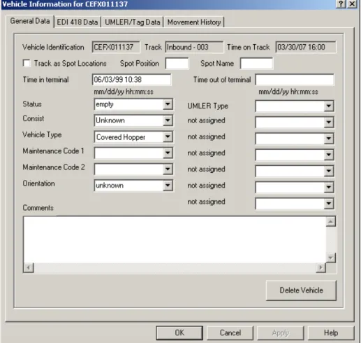
6.1. General Vehicle Information Display
Figure 6 shows the display of the rail car's general data. The Track field shows the current track location of the vehicle if the vehicle has arrived in the terminal. The three-digit number after the dash is the position of the vehicle on the track. If this number is 001, then the vehicle is first car at the left end of the track. If the vehicle has not yet arrived in the terminal, this field has the identifier of the train in which the vehicle will arrive.
The Time on Track field has the date and time the vehicle was placed on the track. If the vehicle has not yet arrived in the terminal, this field will contain the vehicle's latest estimated time of arrival (ETA).
Data in the Time in Terminal or Time out of Terminal fields can either be entered manually or generated from AEI reader input. When a vehicle is reported as having entered the terminal, the date and time of the vehicle's movement into the terminal will appear in the Time in Terminal field.
When a vehicle is reported by one of the designated AEI readers as having left the terminal, the date and time the vehicle passed the reader will appear in the Time out of Terminal field.
AEI Rail & Road Manager
Figure 6 - Vehicle General Data Display
The user can enter up to 20 alphanumeric characters into the Status and Consist fields or select from previous user entries for the fields, which are obtained by clicking the button on the right side of the each field’s box.
For the Vehicle Type field the user can only choose a value from a pre-existing list of entries, which is obtained by clicking the button on the right side of the field. This field is used to determine the vehicle’s graphical representation on the Terminal display. The system will automatically enter a vehicle type into this field based on the data it finds in its internal UMLER file about the vehicle.
The Vehicle Information display includes two Maintenance Code fields. If information about the vehicle came from a portable reader, one or both of these fields may have an entry. To enter or change the code displayed in a Maintenance Code field, click the button at the right side of the field to display the list of codes (e.g., 00 Angle Cock, 01 Air Brakes), and select a code by clicking on it. To remove a maintenance code, select none from the list of codes. See Paragraph 25.2.5 for instructions on how to update the list of maintenance codes.
AEI Rail & Road Manager
Normally, the AEI readers determine a vehicle's orientation. The user, however, can manually change the vehicle's orientation by changing the value in the Orientation field. There are seven fields in this display designated as not assigned. These fields can be assigned names by the user. Each field will accept up to 20 alphanumeric characters.
The user defines these fields by calling up the User Defined Fields display (see Figure
10).
The Comments field allows the user to type up to 200 characters of information about a vehicle. The user may use the Enter key to create multiple lines in this display. A vertical scroll bar is available for scrolling this display.
AEI Rail & Road Manager
6.2. EDI 418 Data Display
Figure 7 shows a typical display of the data the system receives about a vehicle from an EDI 418 message. These fields will be continuously updated as new EDI 418 messages are received about the vehicle. The user can modify the information in these fields, but any new EDI 418 messages will overwrite user-entered information. Please note in the Equipment Status Code field the data entered can only be the two-character code or the words "Load" and "MTY". The system translates "Load" to the "L" code and "MTY" to the "W" code.
AEI Rail & Road Manager
6.3. UMLER/TAG Data Display
Figure 8 shows the display of UMLER and AEI tag data for a vehicle.
The system maintains a subset of an UMLER database. This subset contains only the following fields: Vehicle Type Articulated Count Outside Length Tare Weight Capacity Weight Axle Count
If a vehicle is not found in one of the UMLER databases, all UMLER fields will be blank. The user cannot modify these fields.
Any AEI tag data received from the AEI reader system will appear in the fields at the bottom of the display. The user cannot modify these fields.
AEI Rail & Road Manager
Figure 8 - UMLER/TAG Data Display
6.4. Movement History
Figure 9 shows the Movement History display for the vehicle. Only the last ten movement records for a vehicle will be reported. Each record will show the vehicle's location (can be on either a track or train), the date and time the movement was reported, and who (or what) reported the movement.
Vehicle movements can be reported by an EDI 418 message, an AEI reader site, or a person by manually moving the vehicle on the Terminal display. If a person reports the movement, the log-in name of the person will be shown. If password protection is not turned on and the person is not logged onto the system, the name of the computer the person used to report the movement will be displayed.
Please note that if a vehicle is moved to a different position on the same track, a record will not be made of the movement.
AEI Rail & Road Manager
Figure 9 - Movement History Display
7. USER DEFINED FIELDS
The user calls up the User Defined Fields display by clicking the Setup menu and then
AEI Rail & Road Manager
Figure 10 - User Defined Fields
This display allows the user to customize what data will be included in the vehicles’ data records. For example, a user might want to have the vehicles’ tare, capacity, and actual weights included in the vehicles’ data records. To do this he would first enter, via this display, a field name of up to 20 alphanumeric characters for each new field he wants to include in the vehicles’ data records. He would subsequently place the appropriate data in the fields for each vehicle via the Vehicle Information display.
Instead of entering data into a particular field, the user can define a formula for the field. The program will use this formula to compute a value for the field. For example, the value for the Revenue field, as shown in Figure 10, will be calculated by subtracting the tare weight from the actual weight.
Formulas can use the +, - * and / operators on the contents of any of the numeric fields defined by the user. Constant values can also be used in the formulas. For example, if we wanted the revenue weight to be in tons, the formula we would use would be “(Actual-Tare)/2000”.
Fields that are used in formulas must be defined as being Numeric in the Data Type field.
The User Defined Fields display also allows the user to specify if a customized field is to be left, center, or right justified. This information is used when the field is displayed or printed. For example, if a field contained tare weights, one would probably want to right justify it so that the numbers would line up on the right side of the column when printed.
The user can change the name of a User Defined field at any time. The field’s data in the vehicles’ records will not be modified by this change.
AEI Rail & Road Manager
If a user deletes a field name via this display the name for the field in the Vehicle Information display will return to “not assigned”. The data the user entered into this field for various vehicles will be retained in the vehicles’ data records [not deleted].
8. USER DEFINED VEHICLE COLORS
The user calls up the Vehicle Colors display by clicking the Setup menu and then the
User Defined Vehicle Colors entry. The display shown in Figure 11 will then appear.
Figure 11 - User Defined Colors
The user can assign colors to vehicles based on information contained in the vehicles’ data records. The user has a choice of six colors (black, blue, brown, gray, green and yellow). The color red is reserved for vehicles whose vehicle type is unknown.
The user can specify up to six algorithms to determine a vehicle’s color. In Figure 11, yellow is assigned to vehicles which have a status of empty, blue is assigned to vehicles that have a status equal to bad order and green for vehicles which have been in the terminal for 7 or more days. The entry in the Field box in any color algorithm can be any system defined field or any user defined field to which the user has already assigned a name via the User Defined Fields display. By clicking the button on the right side of the field’s box, a list of allowable fields will be displayed. The user simply clicks the appropriate field for the color algorithm.
AEI Rail & Road Manager
There are four possible entries in the Logic field. These are “Equal to”, “Not equal to”, “Greater or equal to” and “Less or equal to”. A list of these will be displayed when the button on the right side of the Logic field is clicked.
The Test field contains the value against which data in the vehicles’ records will be
tested. By clicking the button on the right side of the field’s box, a list of past user entries for the test field will appear. The user can either select one of the past entries or enter a new test value. If the user only enters the first few characters of a data value, the value will be compared against the same number of characters in the appropriate fields in the vehicles’ data records. For example, if the user entered only “bad” in the Test field instead of “bad order”, all vehicles having a data entry in this field that begins with bad will be assigned the color blue.
Comparisons between the Test field and fields in the vehicle’s data record are not case sensitive. For example, ”bad order” and “Bad Order” are equivalent for these comparisons.
The Time In and Time Out fields can also be used in the color algorithms. In addition to entering a specific date and time in the Test field, the user can also indicate the number of hours or days prior to the current date and time. The program will constantly check the vehicle’s color algorithm by testing the value in the Test field against the current time. In this example, the program will automatically change the color of a vehicle to green when the amount of time the vehicle has been in the yard goes from six to seven days.
The top color algorithm on this display has the highest priority. If a vehicle had both a bad order status and had been in the terminal for over seven days, the vehicle’s color would be blue, because blue was assigned to a higher physical position in the display than the green for 7 or more days in the terminal.
To delete a color algorithm simply select “none” from the list of possible colors.
Vehicles not meeting the criteria of any of the user’s color algorithms are given a default color. The user can either assign a specific color to these vehicles like brown as shown in the Figure 11 or let the program use an unassigned random color. Unassigned random colors are colors that have not been used in the user’s color algorithms. The program will randomly assign these colors to vehicles. If all six vehicle colors are assigned, the default vehicle color will be red.
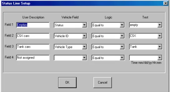
9. USER DEFINED STATUS LINE
Near the bottom of the Terminal display is a status line that contains the number of vehicles in the program’s database. Vehicles on the Outbound track/road are included in this number. The user can also define values for four additional fields in the status line. The user displays the Status Line Setup display (see Figure 12) by clicking the Setup menu and the User Defined Status Line item.
AEI Rail & Road Manager
The status line, at the bottom of the Terminal display, displays the number of vehicles meeting the algorithms defined in the Status Line Setup display. The user names and defines the status line algorithm in the same fashion as was done in the Vehicle Colors display.
Vehicle ID is one of the allowable fields in both the Vehicle Colors and this display. In the Vehicle ID sample in Figure 12 (see Field 2) only the first three characters of the vehicle’s ID are entered in the Test field. This value would be compared to only the first three characters of this field in each of the vehicles’ records.
To delete a status line algorithm, blank the User Description field entry.
Figure 12 - User Defined Status Line
10. ADD, DELETE OR FIND A VEHICLE
10.1. Manually Adding a Vehicle
The user can manually add vehicles to the system by clicking the Add Vehicle button in the tool bar near the top of the Terminal display. Only vehicle numbers that are not already in the system can be added.
10.2. Manually Deleting a Vehicle
Vehicles can be deleted by clicking the Delete Vehicle button in the tool bar near the top of the Terminal display. The user is shown a list of all vehicles in the system sorted in alphanumeric ascending order. The user then selects the vehicle that is to be deleted from this list.
A vehicle can also be deleted from the Vehicle General Data display (Figure 6) by clicking on the Delete Vehicle button, which is located near the bottom of the display.
AEI Rail & Road Manager
All vehicles on a given track can be deleted with one manual operation. See Paragraph 18 of the Track Shortcut Function for details.
10.3. Automatic Vehicle Deletion
Vehicles can be automatically deleted from the system. The user can specify if automatic deletion is allowed, from which tracks/roads vehicles can automatically be deleted, and how long the vehicle must be on the track/road before it is automatically deleted. See Paragraph 10.5 for more details.
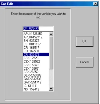
10.4. Finding a Vehicle
To find a vehicle, click the Find Vehicle button on the tool bar of the Terminal display. A list of all vehicles in the system will appear (see Figure 13). Select the vehicle from the list. Once the vehicle has been selected from the list, the cursor will be placed on the vehicle in the Terminal display and a blue rectangle will appear around the vehicle’s ID indicating that it has been selected. The system will automatically scroll to the appropriate place on the Terminal display to show the found vehicle.
Figure 13 - Find a Vehicle Display
10.5. Automatic Deletion of Vehicles
The system will automatically delete vehicles placed on a deletion track/road after a specified period of time if the user chooses the automatic vehicle deletion option. To select this option, click the Automatic Vehicle Deletion menu item under the Setup menu. Figure 14 will then be displayed.
AEI Rail & Road Manager
Figure 14 - Automatic Vehicle Deletion
The user can specify the number of minutes, hours or days the vehicle must be on a deletion track/road before it is automatically deleted. Tracks/roads marked for automatic vehicle deletion are specified by the user when the terminal layout is designed (see Paragraph 23.5 for more details).
11. VEHICLE LIST DISPLAY
The Vehicle List display shows a list of all vehicles meeting a user’s search criteria. All fields associated with a vehicle are included in the Vehicle List display.
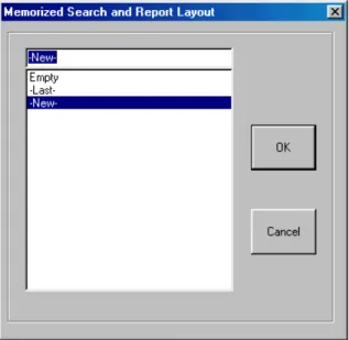
11.1. Vehicle List Search Criteria
To display the Vehicle List, click the Vehicle List button on the tool bar of the Terminal display. The Memorized Search and Report Layout display (see Figure 15) will first appear. The user can select New, Last, or a previously saved vehicle search criteria. The last vehicle search criteria can also be displayed by clicking the Last List button on the tool bar of the Terminal display.
Figure 15 - Vehicle List Memorized Search and Report Layout The next screen used in the search sequence is shown in Figure 16.
AEI Rail & Road Manager
Figure 16 - Vehicle List Search Criteria
If the user chooses Last or a previously saved vehicle search criteria, the algorithms of the previous search will appear on the display shown in Figure 16. If the user chooses New, he will enter the search algorithms for this new vehicle search via this display. With a few exceptions these algorithms operate in the same fashion as the user algorithms in the Vehicle Color and Status Line displays.
A time search can find all vehicles that have either entered the terminal or left the terminal during a specified span of time. The possible contents of the Time for car in facility field are either “Time in” or “Time out.” The user can specify a range of times in
the From and To fields. A specific date and time can be entered into these fields or a
number of hours or days before the current time. The To field also allows “now” to be
entered to specify the current date and time.
If a user enters a specific date and omits the time, 12:00 AM (00:00) will be
assumed in the From field and 11:59 PM (23:59) in the To field. If the year is not
included, the current year is assumed.
If there is an entry in the From field, but not in the To field, the To field is assumed to
be 24 hours after the value in the From field.
There are four search fields in the Vehicle Search Criteria display. With one exception these fields are logically ANDed. This means that the vehicle must meet all of the user-defined algorithms to be included in the Vehicle List display. Not meeting one algorithm’s criteria will prevent the vehicle from being included. There is only one exception to this rule. This exception is when the same field appears in more than one
AEI Rail & Road Manager
algorithm with an Equal to comparison. In this case the algorithms using the same field in the “Equal to” comparison will be logically ORed. If a vehicle meets only one of these algorithms’ criteria, the vehicle will be included. For example, if a user has an algorithm with the Status field equal to empty and an algorithm with the Status field equal to bad order, any vehicle having one of these two values in its Status field will be listed.
Any data can be entered into the Test field. There is a down arrow to the right of the box that, when clicked, will list all memorized values for the field. The user may choose one of these values or enter new data into the Test field.
Comparison tests are made against just the number of characters entered into the Test field. For example, if NIM is entered in the Test field for a track name, all vehicles on tracks that have names beginning with NIM will be listed. If NIM 11 is entered, only vehicles on track name NIM 11 will be listed.
The vehicles’ Comments fields can be searched for a sequence of alphanumeric characters of up to 30 characters in length. The sequence of characters being searched for can exist anywhere in a vehicle’s Comments field. The results of the search would be a list of all vehicles having the desired sequence of characters in their Comments fields.
The user can require a search of comments fields to be case sensitive. If the Case Sensitive box is checked, broken will not be considered equivalent to Broken in the comparison tests.
If the All Comments box is checked, the system will search for and list all vehicles that have comments.
By default, the system always sorts the vehicle list resulting from a search by vehicle ID in ascending alphanumeric order. In addition, the user can specify up to three sort fields. Each of these three fields can be independently sorted in ascending or descending order. The user selects the order by clicking the button on the right side of the Sort Order box (first box under each Sort Field) and clicking the appropriate entry.
Below the Sort Order box is a box for the field that is to be sorted. The user clicks the down arrow on the right side of this box to select the appropriate field to be sorted. Sort Field 1 is the highest sort level and Sort Field 3 the lowest.
To display the Vehicle List the user would then click the OK button. If the user clicks the OK button and if he or she has made changes to the search criteria, the system will first ask if the user wants to save the search criteria and give it a name so that it can be later retrieved. The vehicle list will then be displayed.
Clicking on the Cancel button, instead of the OK button, would cause the last vehicle
AEI Rail & Road Manager
11.2. Vehicle List Display
The Vehicle List display is shown in Figure 17. The total number of vehicles found in the search is shown on the status line under the tool bar. Below the status line and a set of user buttons are the column headers followed by a list of vehicles meeting the search criteria along with user-specified information for each vehicle.
Figure 17 - Vehicle List Display
11.3. Column Widths
The user can adjust the width of the columns in this display. Place the mouse pointer on the vertical line between two column headers (for example, on the line between the Vehicle ID and Track/Train column headers), depress the left mouse key, and drag the mouse to the left or right to resize the columns.
To save the new column sizes, click the Save Column Widths button above the column headers. The next time this display is called up it will have the column widths that were displayed when this button was clicked.
11.4. Column Setup
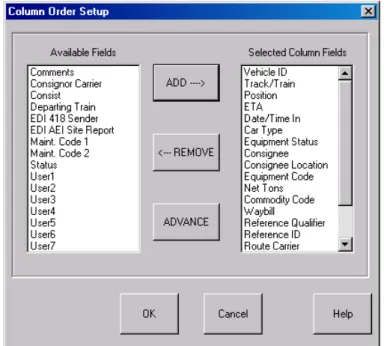
The information displayed in the columns can be customized by the clicking the Column Setup button. This will cause the Column Order Setup display to appear (see Figure 18).
To determine the fields that will be included for each vehicle in the list, select each desired field name in the left-hand list of Available Fields and click the Add button. The field will be moved to the Selected Column Fields list. Pointing the cursor to each field and holding the control key down while clicking the left mouse button can select multiple fields.
To remove fields from the Selected Column Fields list, select the fields to be removed and click the Remove button.
AEI Rail & Road Manager
The fields in the Selected Column Fields list are in the same order they will appear in each line of the Vehicle List. The top field in the Selected Column Fields list will be in the left-most column of each vehicle record in the Vehicle List. Each field down the list will be in the column to the right of the previous field in the vehicle record. To change the order of the fields in the report, select the fields you want to be closer to the left side of the list and click the Advance button. The fields that are selected will move one position up the list or one column to the left in the report. You can advance any field to the top of the list and advance multiple selected fields.
Figure 18 - Vehicle List Column Order Setup Display
11.5. Vehicle Information Display
From the Vehicle List display the user can go to the Vehicle Information display for a particular vehicle by selecting the vehicle in the list and clicking on the View Data button. This will cause the Vehicle Information display for the selected vehicle to appear.
11.6. Vehicle Comments
Because comments placed in a vehicle’s Comments field can be lengthy, they are not shown on the Vehicle List display. To see the comments for a particular vehicle in a Vehicle List, select the vehicle and click the See Comments button above the column headers. The program will then display the comments associated with the selected vehicle.
AEI Rail & Road Manager
11.7. Finding a Vehicle on the Terminal Display
From the Vehicle List display a user can quickly jump to the location of a particular vehicle on the Terminal display. Select the vehicle in the Vehicle List and click the Find Vehicle button above the column headers. This will cause the Terminal display to appear with the mouse pointer on the desired vehicle.
11.8. Exporting Vehicle Data
Data about the listed vehicles can be exported into a delimited text file by clicking the Export Data button. See Paragraph 16 for more details.
11.9. Printing the Vehicle List
When the Vehicle List display is on the screen the user can print this information by choosing the Print menu item under the File menu or by clicking the Print button above the column headers. Either of these actions causes the screen in Figure 19 to be displayed.
Figure 19 - Vehicle List Save Print Layout
The user will select New, Last, or a previously saved print layout, and then the display in Figure 20 will appear.
The system provides the user with a great deal of flexibility in printing reports. The user can specify the report title, if line numbers and date are to be included, which fields should be in the report and in what order, the fonts used for the title, column headings and body, and the printer setup.
AEI Rail & Road Manager
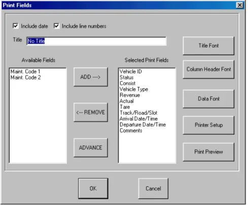
Figure 20 - Vehicle List Print Display
The vehicle records included in the printed report will be the same records displayed in the Vehicle List on the screen. This allows the Vehicle List Search Criteria to be used to determine which vehicles will be shown in the report.
For each vehicle record included in the Vehicle List the user can choose the fields to appear in the printed report via the Vehicle List Print display shown above. Select the desired field(s) from the Available Fields list and then click on the Add button. Fields for the printed report can be chosen either individually or as a group. To select multiple fields hold the control key down while selecting the desired fields. The selected field(s) will be moved to the Selected Print Fields list after the Add button is clicked. In the screen shot above there are few fields in the Available Fields list and many fields in the Selected Print Fields list because many fields have already been selected for the printed report.
To remove fields from the Selected Print Fields list, select the fields to be removed and click the Remove button.
The fields in the Selected Print Fields list are in the same order they will appear in the printed report. The top field in the list will be in the left-most column in the report. Each field down the list will be in the column to the right of the previous field in the list. To change the order of the fields in the report, select the field(s) you want to be closer to the left side of the report and click the Advance button. The field(s) selected will move one position up the list or one column to the left in the report. Fields can be
AEI Rail & Road Manager
advanced either individually or as a group, and any field can be advanced to the top of the list.
By clicking the Preview button on the right side of the display you can view the report prior to printing it.
This same print display is used for printing container, transaction and archive lists.
11.10. Listing or Printing a Single Track’s Vehicle Inventory
The program has a shortcut method for generating a list or printing a list of vehicles on a single track. To start this shortcut, place the mouse cursor on the appropriate track and click the right mouse button. This causes a popup menu to appear. Select the appropriate item to start the process. See Paragraph 18 for more details.
12. PASSWORDS
12.1. Password Maintenance Dialog
The user can set up password protection for each vehicle file. To assign passwords the user chooses the Password Maintenance menu item under the Setup menu, which causes the Password Maintenance dialog to appear (see Figure 21).
Figure 21 - Password Maintenance Dialog
There are three levels of password protection that can be implemented for each vehicle file. These are: read only access, which allows the user to display vehicle database information, but not change it; read/write access, which allows the user to
AEI Rail & Road Manager
display and modify vehicle database information; and system access, which allows the user to modify special system facilities such as passwords and create or modify user specified fields.
To activate these various levels of protection for a given vehicle file, check the Require System Passwords and/or Require User Passwords boxes. If either of the boxes is checked and passwords are not assigned, the default system password user name is “-System-“ and the default password is “Password.” All user names and passwords are case dependent.
To add a new user simply type a user name and password into the appropriate boxes, specify the access level by checking the appropriate access level box, and click the Add button.
To edit a password, select the user name in the User Name list. The information associated with the user name will appear in the User Name and Password boxes to the right of the list. Modify the data in these boxes including the access level and click the Change button to update.
To remove a password, select the user name in the User Name list and click the Remove button.
The system will not allow you to remove the “-System-“ user name or change it. It will, however, allow you to change the password for this user name.
12.2. Password Entry
When a new vehicle file is loaded into the system, the system will check if the file requires a password before it will display the data. If a password is required, the program will ask the user to enter the user name and password. If these are valid for the vehicle file being loaded it will tell the user his or her access level and display the data.
If the user has read/write access for a vehicle file, a transaction record will be created each time the user modifies the vehicle database. This record documents the change to the record and the user who made the change. The user name that was entered with the password is the name saved with the transaction record.
12.3. Logging in a User
A user logs into the system by selecting the User Password menu item under the Setup menu. If the currently displayed vehicle file is password protected the user must have previously been assigned a password for the displayed vehicle file via the Password Maintenance dialog (see Figure 21).
AEI Rail & Road Manager
13. TRANSACTION LIST
13.1. Displaying the Transaction List
To display the transaction list choose the Transaction List menu item under the List menu. The Transaction Search dialog will appear (see Figure 22).
Figure 22 - Transaction Search Dialog
The user can specify a search of the transaction file for specific vehicles over a specific time period. The transaction list displayed can be sorted in either descending or ascending order by the date and time of the transaction. The display will not show more than 5000 transactions at any given time. If the user needs to see transactions that were not displayed, he or she should narrow the search criteria.
13.2. Transaction List Display
Figure 23 shows the Transaction List Display. The fields in this display include the vehicle number, type of transaction, date and time of the transaction, the user name of the user who changed the data record, the field in the data record that was changed, the old data in the field, and the new data. If the user name is unknown (because password protection is not active), the user name will be replaced with the network name of the computer.
AEI Rail & Road Manager
Figure 23 - Transaction List
There are three types of transactions. These are Add, Delete and Modify. The Add type indicates that the vehicle was added to the database. After a vehicle is added to the database a number of the fields are automatically updated which causes a number of Modify type records to be automatically generated. If the vehicle is added by a user with the manual Add a Vehicle command, the user’s name will be in the User ID field of the vehicle record. If no password protection is assigned to the vehicle file and a user name is not entered, the User ID will be shown as Unknown. If the added record is generated by input from an AEI reader, the name of the reader site that added the vehicle will be in User ID field.
When a new vehicle is added to the vehicle database, the user can specify default values for some of the fields. If a default value is used for a field, the User ID will be shown as Default.
The user can ask the system to search the archive file for information on a vehicle. If the archive file contains information on the vehicle, the user can specify which fields in the archive file should be used to update fields in the new record on the vehicle. In this case Restored will be shown as the User ID. See Paragraph 15.
The Comments field can be as long as 200 characters. If the transaction record is due to a modification to the Comments field, the user must click the See Comments button after selecting the appropriate record.
The width of the columns in this display can be adjusted by placing the mouse pointer on the vertical line between two column headers (for example on the line between the Vehicle ID and Type column headers), depressing the left mouse key, and dragging the mouse to the left or right to resize the columns.
AEI Rail & Road Manager
The new column sizes can be saved by clicking the Save Column Widths button above the column headers. The next time this display is accessed it will have the same column widths that were displayed when the Save Column Widths button was clicked.
13.3. Printing the Transaction List
When the Transaction List display is on the screen the user can print this information by choosing the Print menu item under the File menu or by clicking the Print button above the column headers. Either of these actions causes the Transaction Print dialog screen to be displayed. This dialog is similar to the dialog that was displayed for
printing the Vehicle List in Figure 20 except the fields that can be printed are different.
13.4. Transaction File Structure
The transaction file is called transact.txt and is a text file. This file can be viewed from Notepad or any other word processing program.
Each record in the file represents one transaction with commas delimiting each of the fields. The fields by their order in the record are:
Vehicle Number
Transaction Date and Time
Transaction Type
User or Computer Identification
Modified Field Name
Old Data
New Data
If the transaction type is Add or Delete the last three fields are not in the record and commas are not used to hold their spaces in the record. The last field in these types of records would be the User ID.
If the field that was modified is the Comments field, the old and new data fields in this record will be enclosed in quotes. This allows the data in the Comments field to contain commas.
14. ARCHIVE LIST
14.1. Displaying the Archive List
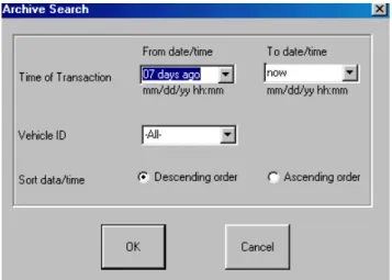
The Archive List is a list of deleted vehicle information. This list can be displayed by choosing the Archive List menu item under the List menu. The Archive Search dialog will appear (see Figure 24).
AEI Rail & Road Manager
Figure 24 - Archive Search Dialog
The archive file contains the records of vehicles deleted from the system. The user can specify a search of the archive file for specific vehicles over a specific time period. The deletion records displayed can be sorted in either descending or ascending order by the date and time the deletion took place. The display will not show more than 5000 records at any given time. If the user needs to see records that are not displayed, he or she should narrow the search criteria.
14.2. Archive List Display
Figure 25 shows the Archive List display. Each entry in this list contains all of the fields in the vehicle record at the time the vehicle was deleted from the system, the date and time the vehicle was deleted, and the user identification of who deleted the record.
Figure 25 - Archive List Display
The Comments field can be as long as 200 characters. If the deleted vehicle record has information in its Comments field, to display this field the user must click the See Comments button after selecting the appropriate record.
AEI Rail & Road Manager
The user can adjust the width of the columns in this display. Place the mouse pointer on the vertical line between two column headers (for example, on the line between the Vehicle ID and Delete Date/Time column headers), depress the left mouse key and drag the mouse to the left or right to resize the columns.
The new column sizes can be saved by clicking on the Save Column Widths button above the column headers. The next time this display is accessed it will have the same column widths that were displayed when the Save Column Widths button was clicked.
14.3. Restoring a Deleted Vehicle
The user can restore a deleted vehicle to the Terminal display by selecting the vehicle record from the Archive List display and clicking the Restore Vehicle button.
14.4. Printing the Archive List
When the Archive List display is on the screen the user can print this information by choosing the Print menu item under the File menu or by clicking the Print button above the column headers. Either of these actions causes an Archive Print Dialog screen to be displayed. This dialog is similar to the dialog that was displayed for printing the
Vehicle List in Figure 20 except the fields that can be printed are different.
14.5. Archive File Structure
The archive file is called archive.txt and is a text file. This file can be viewed from Notepad or any other word processing program.
Each record in the file represents one vehicle deletion record with commas delimiting each of the fields. The fields by their order in the record are:
Deletion Date and Time
Vehicle Number
User or Computer Identification
Status
Consist
Vehicle Type
The Seven User Defined Fields
Comments
15. RESTORE FIELDS
When a new vehicle is added, either manually by a user or automatically by an AEI reader, the system searches the archive file for the most recent record for that vehicle. If the vehicle was entered previously, the system will update the new vehicle’s record from the last information it found on the vehicle. The user can specify which fields he or she wants to be automatically updated. This feature can be very helpful, for example, when the user stores the vehicle’s tare weight in the vehicle’s record.
AEI Rail & Road Manager
Once the user inputs the tare weight for the vehicle, each time the vehicle re-enters the system, this tare weight will be included in the new record on the vehicle.
By choosing the Archive Restore Fields menu item under the Setup menu the Restore Fields dialog will appear (see Figure 26).
15.1. Restore Field Dialog
Figure 26 - Restore Field Dialog
The Restore Fields dialog operates in a similar fashion to the Print dialog discussed in Paragraph 11.9. The user determines the field(s) to be automatically updated from a vehicle’s last deleted record by placing the cursor on the field name(s) in the list of Available Fields and clicking the left mouse button, which causes the field{s] to be highlighted. The user then clicks the Add button, which causes the field to be moved to the Selected Restore Fields list. Multiple fields can be selected by pointing the cursor at each field and holding the Control key down while clicking the left mouse button.
To remove fields from the Selected Restore Field list, select the field to be removed and click the Remove button.
If the system cannot find an old record on a vehicle, it will use the user default values for the three primary fields, which are Vehicle Type, Status and Consist. All other fields in the record will be initialized to blanks.
16. EXPORT DATA
To provide maximum flexibility, the system has the capability to create an export file for the vehicle records. This is a text file with the fields delimited by a character the user
AEI Rail & Road Manager
can choose. The user can also choose which fields will be included in each export record. With this capability the information in the system can be easily transferred to various commercial word processing, spreadsheet or database programs or to user-written programs allowing the user to generate special reports and perform statistical analyses.
By choosing the Export menu item under the File menu the Export Fields dialog will appear and ask for the Export file name.
16.1. Export Dialog
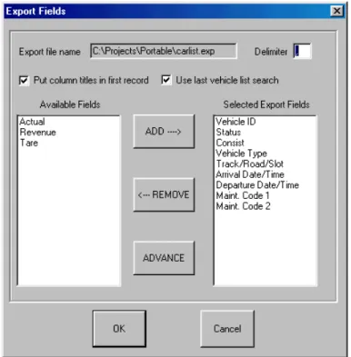
Once the name is entered, the display shown in Figure 27 will appear. The user can specify a one-character delimiter (usually a comma or a space), which will be placed between each field in the records. The user can also specify if the first record of the file will contain the names of the fields in the order they appear in each of the vehicle records to be exported. The last option before selecting the fields to be included in the export record concerns whether all of the vehicles’ records will be included in the
export file, or just the ones found in the last Vehicle List Search.
Figure 27 - Export Dialog
The user then selects the fields to be included in each vehicle’s export record as was done with the Print dialog described in Paragraph 9.5. The user determines what fields will be included in each export record by placing the cursor on each desired field's name in the left hand list of Available Fields and clicking the left mouse button. This causes the field to be highlighted. The user then clicks the Add button, which
AEI Rail & Road Manager
moves it to the Selected Export Fields list. Multiple fields can be selected by pointing the cursor at each field and holding the Control key down while clicking the left mouse button.
To remove fields from the Selected Export Fields list, select the field to be removed and click the Remove button.
The fields in the Selected Export Fields list are in the order in which they will be listed in each export vehicle record. The top field in the list will be the first field. Each field down the list will be the next field in the export record. To move a field or fields closer to the beginning of the record, select the field(s) and click the Advance button. Multiple fields can be selected as has been described above. The field(s) selected will move one position up the list or one field closer to the beginning of the record.
16.2. Export Vehicle Inventory on a Single Track/Road
The program has a shortcut method for exporting a single track/road’s vehicle inventory. To start this shortcut place the mouse cursor on the appropriate track/road on the Terminal display and click the right mouse button. This causes a popup menu shown in Figure 28 to appear. Select the appropriate item to start the process.
17. REVERSE TRACK INVENTORY
To reverse the order in which vehicles are displayed on a track (flip a track’s inventory making the left most vehicle, the right most vehicle, etc.), place the mouse cursor on the track to be reversed and click the right mouse button. This will cause a pop-up menu (see Figure 28) to display. Click the Reverse track consist item to flip the track’s inventory.
18. SUMMARY OF TRACK/ROAD SHORTCUT FUNCTIONS
In summary, the system provides easy shortcut methods for exporting, listing, printing, reversing inventory or deleting vehicles on a track. To implement any of these shortcut functions, place the mouse cursor on the track for which the function is desired and click the right mouse button. The pop-up menu in Figure 28 will appear.
AEI Rail & Road Manager
Figure 28 - Shortcut Pop-up Menu
Click the appropriate item to begin the dialog for a function. The functions are described in the paragraphs listed below:
Exporting Track Inventory – Paragraph 16
Listing Track Inventory - Paragraph 11.2
Printing Track Inventory - Paragraph 11.9
Reversing Track Inventory - Paragraph 17
Deleting Track Inventory - Paragraph 10.1
19. FILE MAINTENANCE
There are three major files that should be maintained. These are the Vehicle Data file, the Transaction file, and the Archive Delete file.
19.1. Manual File Backup
To manually backup the Vehicle Data, Transaction or Archive Delete files, select the appropriate back-up menu item under the File menu. The Vehicle Data file that will be backed up is the file that is currently being displayed. All back-up files are given the .bak extension unless the user specifies another extension.
19.2. Automatic Backup of Vehicle Data File
The system can automatically make back-up copies of the Vehicle Data file via the display shown in Figure 29. Select the File Maintenance menu item under the Setup menu to bring this screen up.
The user can specify whether the Vehicle Data file should be automatically backed up, how often, and the required number of back-up copies. The time can be specified in