ARC-1110/1120/1130/1160/1170
( 4/8/12/16/24-port PCI-X SATA RAID Controllers )
ARC-1130ML/1160ML/1160ML2
( 12/16-port Multi-lane connector PCI-X SATA RAID
Control-lers )
ARC-1210/1220/1230/1260/1280/
( 4/8/12/16/24-port PCI-Express SATA RAID Controllers )
ARC-1231ML/1261ML/1280ML
(12/16/24-port PCI-Express SATA RAID Controllers)
ARC-1201 (OEM Version)
(8-Port PCI-Express x1 SATA RAID Controller)
SATA RAID Cards
USER Manual
Version: 4.01
Microsoft WHQL Windows Hardware Compatibility
Test
ARECA is committed to submitting products to the Microsoft Windows Hardware Quality Labs (WHQL), which is required for participation in the Windows Logo Program. Successful passage of the WHQL tests results in both the “Designed for Windows” logo for qualifying ARECA PCI-X and PCI-Express SATA RAID controllers and a listing on the Mi-crosoft Hardware Compatibility List (HCL).
Copyright and Trademarks
The information of the products in this manual is subject to change without prior notice and does not represent a commitment on the part of the vendor, who assumes no liability or responsibility for any errors that may appear in this manual. All brands and trademarks are the properties of their respective owners. This manual contains materials protected under International Copyright Conventions. All rights
reserved. No part of this manual may be reproduced in any form or by any means, electronic or mechanical, including photocopying, without the written permission of the manufacturer and the author. All inquiries should be addressed to Areca Technology Corporation.
FCC STATEMENT
This equipment has been tested and found to comply with the lim-its for a Class B digital device, pursuant to part 15 of the FCC Rules. These limits are designed to provide reasonable protection against in-terference in a residential installation. This equipment generates, uses, and can radiate radio frequency energy and, if not installed and used in accordance with the instructions, may cause harmful interference to radio communications. However, there is no guarantee that interfer-ence will not occur in a particular installation.
Contents
1. Introduction ... 10
1.1 Overview ... 10
1.2 Features ... 12
2. Hardware Installation ... 16
2.1 Before Your Begin Installation ... 16
2.2 Board Layout ... 17
2.3 Installation ... 23
3. McBIOS RAID Manager ... 42
3.1 Starting the McBIOS RAID Manager ... 42
3.2 McBIOS RAID manager ... 43
3.3 Configuring Raid Sets and Volume Sets ... 44
3.4 Designating Drives as Hot Spares ... 44
3.5 Using Quick Volume/Raid Setup Configuration ... 45
3.6 Using RAID Set/Volume Set Function Method ... 46
3.7 Main Menu ... 48
3.7.1 Quick Volume/RAID Setup ... 49
3.7.2 Raid Set Function ... 52
3.7.2.1 Create Raid Set ... 53
3.7.2.2 Delete Raid Set ... 54
3.7.2.3 Expand Raid Set ... 55
• Migrating ... 56
3.7.2.4 Activate Incomplete Raid Set ... 56
3.7.2.5 Create Hot Spare ... 57
3.7.2.6 Delete Hot Spare ... 58
3.7.2.7 Raid Set Information ... 58
3.7.3 Volume Set Function ... 59
3.7.3.1 Create Volume Set ... 59
• Volume Name ... 61 • Raid Level ... 61 • Capacity ... 62 • Stripe Size ... 64 • SCSI Channel ... 64 • SCSI ID ... 65 • Cache Mode ... 66 • Tag Queuing ... 66
3.7.3.2 Delete Volume Set ... 67
3.7.3.4 Check Volume Set ... 69
3.7.3.5 Stop Volume Set Check ... 70
3.7.3.6 Display Volume Set Info. ... 70
3.7.4 Physical Drives ... 71
3.7.4.1 View Drive Information ... 71
3.7.4.2 Create Pass-Through Disk ... 72
3.7.4.3 Modify a Pass-Through Disk ... 72
3.7.4.4 Delete Pass-Through Disk ... 73
3.7.4.5 Identify Selected Drive ... 73
3.7.5 Raid System Function ... 74
3.7.5.1 Mute The Alert Beeper ... 74
3.7.5.2 Alert Beeper Setting ... 75
3.7.5.3 Change Password ... 75
3.7.5.4 JBOD/RAID Function ... 76
3.7.5.5 Background Task Priority ... 77
3.7.5.6 Maximum SATA Mode ... 77
3.7.5.7 HDD Read Ahead Cache ... 78
3.7.5.8 Volume Data Read Ahead ... 78
3.7.5.9 Stagger Power On ... 79
3.7.5.10 Empty HDD slot HDD ... 80
3.7.5.11 HDD SMART Status Polling ... 81
3.7.5.12 Controller Fan Detection ... 81
3.7.5.13 Disk Write Cache Mode ... 82
3.7.5.14 Capacity Truncation ... 82
3.7.6 Ethernet Configuration (Ethernet Port Support) ... 83
3.7.6.1 DHCP Function ... 84
3.7.6.2 Local IP address ... 85
3.7.6.3 Ethernet Address ... 86
3.7.7 View System Events ... 86
3.7.8 Clear Events Buffer ... 87
3.7.9 Hardware Monitor ... 87
3.7.10 System Information ... 87
4. Driver Installation ... 89
4.1 Creating the Driver Diskettes ... 89
4.2 Driver Installation for Windows ... 91
4.2.1 New Storage Device Drivers in Windows 2003/XP-64/Vista . 91 4.2.2 Install Windows 2000/XP/2003/Vista on a SATA RAID Vol-ume ... 91
4.2.2.1 Installation Procedures ... 91
4.2.3 Installing Controller into an Existing Windows 2000/
XP/2003/Vista Installation ... 93
4.2.3.1 Making Volume Sets Available to Windows System ... 95
4.2.4 Uninstall controller from Windows 2000/XP/2003/Vista .... 95
4.3 Driver Installation for Linux ... 96
4.4 Driver Installation for FreeBSD ... 97
4.5 Driver Installation for Solaris 10 ... 97
4.6 Driver Installation for Mac 10.x ... 97
4.7 Driver Installation for UnixWare 7.1.4 ... 98
4.8 Driver Installation for NetWare 6.5 ... 99
5. ArcHttp Proxy Server Installation ... 100
5.1 For Windows... 101 5.2 For Linux ... 102 5.3 For FreeBSD ... 104 5.4 For Solaris 10 x86 ... 104 5.5 For Mac OS 10.x ... 104 5.6 ArcHttp Configuration ... 105
6. Web Browser-based Configuration ... 108
6.1 Start-up McRAID Storage Manager ... 108
• Start-up McRAID Storage Manager from Windows Local Admin-istration ... 109
• Start-up McRAID Storage Manager from Linux/FreeBSD/So-laris/Mac Local Administration ... 110
• Start-up McRAID Storage Manager Through Ethernet port (Out-of-Band) ... 110
6.2 McRAID Storage Manager ... 111
6.3 Main Menu ... 112
6.4 Quick Function ... 112
6.5 RaidSet Functions ... 113
6.5.1 Create Raid Set ... 113
6.5.2 Delete Raid Set ... 114
6.5.3 Expand Raid Set ... 114
6.5.4 Activate Incomplete Raid Set ... 115
6.5.5 Create Hot Spare ... 116
6.5.6 Delete Hot Spare ... 116
6.5.7 Rescue Raid Set ... 116
6.5.8 Offline Raid Set ... 117
6.6 Volume Set Functions ... 117
6.6.1 Create Volume Set ... 117
• Volume Name ... 118
• Capacity ... 118
• Greater Two TB Volume Support ... 118
• Initialization Mode ... 119
• Stripe Size ... 119
• Cache Mode ... 119
• Tag Queuing ... 120
6.6.2 Delete Volume Set ... 120
6.6.3 Modify Volume Set ... 120
6.6.3.1 Volume Growth ... 121
6.6.3.2 Volume Set Migration ... 122
6.6.4 Check Volume Set ... 122
6.6.5 Stop VolumeSet Check ... 123
6.7 Physical Drive ... 123
6.7.1 Create Pass Through Disk ... 123
6.7.2 Modify Pass Through Disk ... 124
6.7.3 Delete Pass Through Disk ... 124
6.7.4 Identify Selected Drive ... 125
6.8 System Controls ... 125
6.8.1 System Config ... 125
• System Beeper Setting ... 126
• Background Task Priority ... 126
• JBOD/RAID Configuration ... 126
• Maximun SATA Supported ... 126
• HDD Read Ahead Cache ... 126
• Stagger Power on ... 127
• Empty HDD Slot LED ... 127
• Disk Write Cache Mode ... 128
• Disk Capacity Truncation Mode ... 128
6.8.2 Ethernet Configuration (Ethernet Port Support) ... 129
6.8.3 Alert by Mail Configuration (Ethernet Port Support) ... 130
6.8.4 SNMP Configuration (Ethernet Port Support) ... 131
• SNMP Trap Configurations ... 131
• SNMP System Configurations ... 131
• SNMP Trap Notification Configurations ... 131
6.8.5 NTP Configuration (Ethernet Port Support) ... 132
• NTP Sever Address ... 132
• Time Zone ... 132
• Automatic Daylight Saving... 132
6.8.6 View Events/Mute Beeper ... 133
6.8.7 Generate Test Event ... 133
6.8.9 Modify Password ... 134
6.9 Information ... 135
6.9.1 RaidSet Hierarchy ... 135
6.9.2 System Information ... 136
6.9.3 Hardware Monitor ... 137
Appendix A ... 138
Upgrading Flash ROM Update Process ... 138
Upgrading Firmware Through McRAID Storage Manager ... 138
Upgrading Firmware Through nflash DOS Utility ... 140
Upgrading Firmware Through CLI ... 141
Appendix B ... 142
Battery Backup Module (ARC6120-BAT-Txx) ... 142
BBM Components ... 142
Status of BBM ... 142
Installation ... 142
Battery Backup Capacity ... 143
Operation ... 143
Changing the Battery Backup Module ... 143
BBM Specifications ... 144
Appendix C ... 145
SNMP Operation & Definition ... 145
Appendix D ... 152
Event Notification Configurations ... 152
A. Device Event ... 152
B. Volume Event ... 153
C. RAID Set Event ... 154
D. Hardware Monitor Event ... 154
Appendix E ... 156
RAID Concept ... 156
RAID Set ... 156
Volume Set ... 156
Ease of Use Features ... 157
• Foreground Availability/Background Initialization ... 157
• Online Array Roaming ... 157
• Online Capacity Expansion ... 157
• Online RAID Level and Stripe Size Migration ... 159
• Online Volume Expansion ... 160
High availability ... 160
• Global Hot Spares ... 160
• Hot-Swap Disk Drive Support ... 161
• Auto Declare Hot-Spare ... 161
• Adjustable Rebuild Priority ... 162
High Reliability ... 163
• Hard Drive Failure Prediction ... 163
• Auto Reassign Sector... 163
• Consistency Check ... 164 Data Protection ... 164 • Battery Backup ... 164 • Recovery ROM ... 165 Appendix F ... 165 Understanding RAID ... 165 • RAID 0 ... 166 • RAID 1 ... 166 • RAID 10(1E) ... 167 • RAID 3 ... 167 • RAID 5 ... 168 • RAID 6 ... 169 Appendix G ... 172 Technical Support ... 172
INTRODUCTION
1. Introduction
This section presents a brief overview of the SATA RAID Series con-troller, ARC-1110/1120/1130/1130ML/1160/1160ML/1160ML2/1170 (4/8/12/16/24-port PCI-X SATA RAID Controllers), ARC-1201(OEM version 8-port PCIex1 controller) and ARC-1210/1220/1230/1231ML/ 1260/1261ML/1280/1280ML (4/8/12/16/24-port PCIe SATA RAID Controllers).
1.1 Overview
The ARC-11xx and ARC-12xx series of high-performance Serial ATA RAID controllers support a maximum of 4, 8, 12, 16, or 24 SATA II peripheral devices (depending on model) on a single controller. The ARC-11xx series for the PCI-X bus and the ARC-12xx series for the
PCI-Express bus. When properly configured, these SATA control -lers provide non-stop service with a high degree of fault tolerance through the use of RAID technology and can also provide advanced array management features.
The 4 and 8 port SATA RAID controllers are low-profile PCI cards,
ideal for 1U and 2U rack-mount systems. These controllers utilize
the same RAID kernel that has been field-proven in Areca existing
external RAID controllers, allowing Areca to quickly bring stable and reliable RAID controllers to the market.
Unparalleled Performance
The SATA RAID controllers provide reliable data protection for desktops, workstations, and servers. These cards set the stan-dard with enhancements that include a high-performance Intel I/O Processor, a new memory architecture, and a high performance PCI bus interconnection. The 8/12/16/24-port controllers with the RAID 6 engine built-in can offer extreme-availability RAID 6 func-tionality. This engine can concurrently compute two parity blocks with performance very similar to RAID 5. The controllers by default support 256MB of ECC SDRAM memory for Intel IOP331/332/333. ARC-1201 RAID controller only supports 128MB DDR2-400 SDRAM. The 12/16/24 port controllers support one DDR333 SODIMM socket that allows for upgrading up to 1GB of memory. The 12/16/24
INTRODUCTION
port controllers support one DDR2-533 DIMM socket that allows for upgrading up to 2GB of memory. The controllers use Marvell 4/8 channel SATA PCI-X controller chips, which can simultaneously communicate with the I/O processor and read or write data on multiple drives.
Unsurpassed Data Availability
As storage capacity requirements continue to rapidly increase, us-ers require greater levels of disk drive fault tolerance, which can be implemented without doubling the investment in disk drives. RAID 1 (mirroring) provides high fault tolerance. However, half of the drive capacity of the array is lost to mirroring, making it too costly for most users to implement on large volume sets due to doubling the number of drives required. Users want the protection of RAID 1 or better with an implementation cost comparable to RAID 5. RAID 6 can offer fault tolerance greater than RAID 1 or RAID 5 but only consumes the capacity of 2 disk drives for distributed parity data. The 8/12/16/24-port RAID controllers provide RAID 6 functionality to meet these demanding requirements.
The SATA RAID controllers also provide RAID levels 0, 1, 10(1E),
3, 5, 6, Single Disk or JBOD configurations. Its high data avail -ability and protection is derived from the following capabilities: Online RAID Capacity Expansion, Array Roaming, Online RAID Level / Stripe Size Migration, Dynamic Volume Set Expansion, Global Online Spare, Automatic Drive Failure Detection, Automatic Failed Drive Rebuilding, Disk Hot-Swap, Online Background Rebuilding and Instant Availability/Background Initialization. During the
con-troller firmware flash upgrade process, it is possible that an error results in corruption of the controller firmware. This could result
in the device becoming non-functional. However, with our Redun-dant Flash image feature, the controller will revert back to the last
known version of firmware and continue operating. This reduces the risk of system failure due to firmware crashes.
Easy RAID Management
The SATA RAID controller utilizes built-in firmware with an embed -ded terminal emulation that can access via hot key at M/B BIOS
INTRODUCTION
boot-up screen. This pre-boot manager utility can be used to sim-plify the setup and management of the RAID controller. The
con-troller firmware also contains a web browser-based program that can be accessed through the ArcHttp proxy server function in Win-dows, Linux, FreeBSD and more environments. This web browser-based McRAID storage manager utility allows both local and remote
creation and modification RAID sets, volume sets, and monitoring
of RAID status from standard web browsers.
1.2 Features
Adapter Architecture
• Intel IOP 331 I/O processor (ARC-11xx series)
• Intel IOP 332/IOP 333 I/O processor (ARC-12xx series) • Intel IOP341 I/O processor (ARC-12x1ML/ARC-1280ML/1280) • ARM storage I/O processor (ARC-1201, OEM version)
• 64-bit/133MHz PCI-X Bus compatible • PCI Express x8 compatible (IOP332/333) • PCI Express x1 compatible (ARC-1201) • 128MB DDR2-400 SDRAM (ARC-1201)
• 256MB on-board DDR333 SDRAM with ECC protection (4/8-port) • One SODIMM Socket with default 256 MB of DDR333 SDRAM with ECC protection, upgrade to 1GB (12, 16 and 24-port cards only)
• One DIMM Socket with default 256 MB of DDR2-533 SDRAM with ECC protection, upgrade to 2GB(ARC-12xxML and ARC- 1280)
• An ECC or non-ECC SDRAM module using x8 or x16 chip organi- zation
• Support up to 4/8/12/16/24 SATA ll drives • Write-through or write-back cache support
• Multi-adapter support for large storage requirements • BIOS boot support for greater fault tolerance
• BIOS PnP (plug and play) and BBS (BIOS boot specification)
support
• Supports extreme performance Intel RAID 6 functionality • NVRAM for RAID event & transaction log
• Battery backup module (BBM) ready (Depend on motherboard, ARC-1201 without BBM support)
INTRODUCTION
RAID Features
• RAID level 0, 1, 10(1E), 3, 5, 6, Single Disk and JBOD • Multiple RAID selection
• Online array roaming
• Online RAID level/stripe size migration
• Online capacity expansion & RAID level migration simultaneously • Online volume set growth
• Instant availability and background initialization
• Automatic drive insertion/removal detection and rebuilding • Greater than 2TB per volume set for 64-bit LBA
• Redundant flash image for adapter availability
• Support SMART, NCQ and OOB staggered spin-up capable drives
Monitors/Notification
• System status indication through LED/LCD connector, HDD activity/fault connector, and alarm buzzer
• SMTP support for email notification
• SNMP agent supports for remote SNMP manager • I2C Enclosure Management Ready (IOP331/332/333) • I2C & SGPIO Enclosure Management Ready (IOP341/ARM) RAID Management
• Field-upgradeable firmware in flash ROM
• Ethernet port support on 12/16/24-port and ARC-1201 In-Band Manager
• Hot key boot-up McBIOS RAID manager via M/B BIOS
• Support controller’s API library, allowing customer to write its own AP
• Support Command Line Interface (CLI)
• Browser-based management utility via ArcHttp proxy server • Single Admin Portal (SAP) monitor utility
• Disk Stress Test (DST) utility for production in Windows Out-of-Band Manager
• Firmware-embedded browser-based MCRAID storage manager, SMTP manager, SNMP agent and Telent function via Ethernet port (for 12/16/24-port adapter and ARC-1201 )
• Support controller’s API library for customer to write its own AP (for 12/16/24-port adapter and ARC-1201)
INTRODUCTION
PCI-X RAID Card Comparison (ARC-11XXML)
1130ML 1160ML/1160ML2
RAID processor IOP331
Host Bus Type PCI-X 133MHz
RAID 6 support Yes Yes
Cache Memory One SODIMM One SODIMM
Drive Support 12 x SATA ll 16 x SATA ll
Disk Connector 3 x Multi-lane 4 x Multi-lane/4 x SFF-8087 Internal PCI-X RAID Card Comparison (ARC-11XX)
1110 1120 1130 1160 1170
RAID processor IOP331
Host Bus Type PCI-X 133MHz
RAID 6 support Yes Yes Yes Yes Yes
Cache Memory 256MB 256MB One
SO-DIMM One SO-DIMM One SO-DIMM Drive Support 4 x SATA ll 8 x SATA ll 12 x SATA ll 16 x SATA ll 24 x SATA ll
Disk Connector SATA SATA SATA SATA SATA
Operating System
• Windows 2000/XP/Server 2003/Vista • Red Hat Linux
• SuSE Linux • FreeBSD
• Novell Netware 6.5 • Solaris 10 X86/X86_64 • SCO Unixware 7.1.4
• Mac OS 10.X (EFI BIOS support)
INTRODUCTION
Internal PCI-Express RAID Card Comparison (ARC-12XX)
1210 1220 1230 1260 1201
RAID processor IOP332 IOP333 ARM
Host Bus Type PCI-Express x8 PCI-Express x1
RAID 6 support N/A Yes Yes Yes Yes
Cache Memory 256MB 256MB One SODIMM One SODIMM 128MB Drive Support 4 * SATA ll 8 * SATA ll 12 x SATA ll 16 x SATA ll 8 x SATA ll
Disk Connector SATA SATA SATA SATA 2 x SFF-8087
Internal PCI-Express RAID Card Comparison (ARC-12X1ML/1280)
1231ML 1261ML 1280ML 1280
RAID processor IOP341
Host Bus Type PCI-Express x8
RAID 6 support Yes Yes Yes Yes
Cache Memory One DDR2 DIMM (Default 256MB, Upgrade to 2GB) Drive Support 12 x SATA ll 16 x SATA ll 24 x SATA ll 24 x SATA ll Disk Connector 3 x SFF-8087 4 x SFF-8087 6 x SFF-8087 24 x SATA
HARDWARE INSTALLATION
2. Hardware Installation
This section describes the procedure for installing the SATA RAID con-trollers.
2.1 Before Your Begin Installation
Thank you for purchasing the SATA RAID Controller as your RAID data storage and management system. This user guide gives you
a simple step-by-step instructions for installing and configuring
the SATA RAID Controller. To ensure personal safety and to protect your equipment and data, please read the information carefully in pack content list before you begin installing.
Package Contents
If any items listed in your package is missing, please contact your local dealers before proceeding with installation (disk drives and disk mounting brackets are not included):
ARC-11xx Series SATA RAID Controller
• 1 x PCI-X SATA RAID Controller in an ESD-protective bag • 4/8/12/16/24 x SATA interface cables (one per port) • 1 x Installation CD
• 1 x User Manual
ARC-1201 (OEM version) SATA RAID Controller
• 1 x PCI-Express x1 SATA RAID Controller in an ESD-protective bag
• 1 x Installation CD • 1 x User Manual
ARC-12xx Series SATA RAID Controller
• 1 x PCI-Express SATA RAID Controller in an ESD-protective bag • 4/8/12/16 x SATA interface cables (one per port)
• 1 x Installation CD • 1 x User Manual
HARDWARE INSTALLATION
2.2 Board Layout
Follow the instructions below to install a PCI RAID Card into your PC / Server.
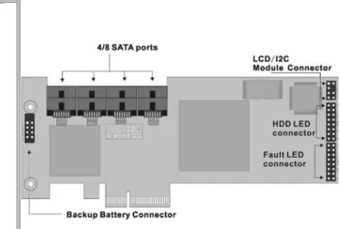
Figure 2-1, ARC-1110/1120 (4/8-port PCI-X SATA RAID Controller)
Figure 2-2, ARC-1210/1220 (4/8-port PCI-Express SATA RAID Con-troller)
HARDWARE INSTALLATION
Figure 2-4, ARC-1201 (8-port PCI-Express SATA RAID Controller)
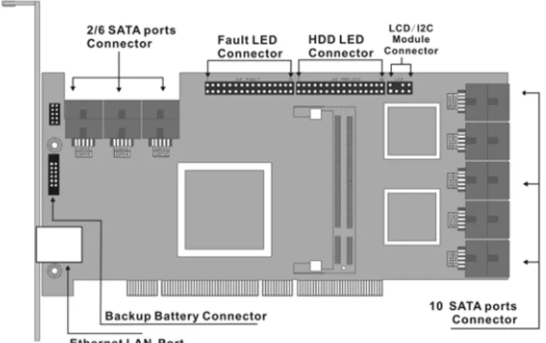
Figure 2-5, ARC-1130/1160 (12/16-port PCI-X SATA RAID Control-ler)
HARDWARE INSTALLATION
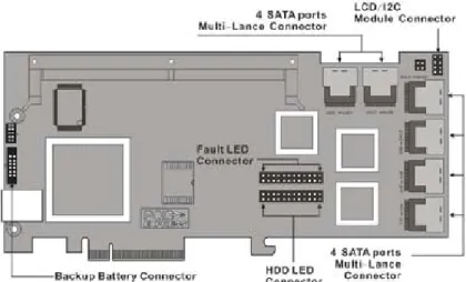
Figure 2-6, ARC-1130ML/1160ML (12/16-port PCI-X SATA RAID Controller)
Figure 2-7, ARC-1230/1260 (12/16-port PCI-EXpress SATA RAID Controller)
HARDWARE INSTALLATION
Figure 2-8, ARC-1170 (24-port PCI-X SATA RAID Controller)
HARDWARE INSTALLATION
Figure 2-10, ARC-1231ML/1261ML/1280ML (12/16/24-port PCI-Ex-press SATA RAID Controller)
Tools Required
An ESD grounding strap or mat is required. Also required are stan-dard hand tools to open your system’s case.
System Requirement
The controller can be installed in a universal PCI slot and requires a motherboard that:
ARC-11xx series required one of the following:
• Complies with the PCI Revision 2.3 32/64-bit 33/66MHz, 3.3V. • Complies with the PCI-X 32/64-bit 66/100/133 MHz, 3.3V. ARC-12xx series requires:
• Complies with the PCI-Express x8
It can also work on the PCIe x1, x4, x8 and x16 signal with x8 or x16 slot M/B.
ARC-1201 requires:
• Complies with the PCI-Express x1
It can also work on the PCIe x1, x4, x8 and x16 signal M/B.
The SATA RAID controller may be connected to up to 4 or 8 SATA ll hard drives using the supplied cables.
Optional cables are required to connect any drive activity LEDs and fault LEDs on the enclosure to the SATA RAID controller.
HARDWARE INSTALLATION
Warning:
High voltages may be found inside computer equipment. Be-fore installing any of the hardware in this package or remov-ing the protective covers of any computer equipment, turn off power switches and disconnect power cords. Do not re-connect the power cords until you have replaced the covers.
Electrostatic Discharge
Static electricity can cause serious damage to the electronic com-ponents on this SATA RAID controller. To avoid damage caused by electrostatic discharge, observe the following precautions:
• Do not remove the SATA RAID controller from its anti-static packaging until you are ready to install it into a computer case. • Handle the SATA RAID Controller by its edges or by the metal mounting brackets at its each end.
• Before you handle the SATA RAID controller in any way, touch a grounded, anti-static surface, such as an unpainted portion of the system chassis, for a few seconds to discharge any built-up static electricity.
Installation Tools
The following items may be needed to assist with installing the SATA RAID controller into an available PCI expansion slot. • Small screwdriver
• Host system hardware manuals and manuals for the disk or enclosure being installed.
Personal Safety Information
To ensure personal safety as well as the safety of the equipment: • Always wear a grounding strap or work on an ESD-protective mat.
• Before opening the system cabinet, turn off power switches and unplug the power cords. Do not reconnect the power cords until you have replaced the covers.
HARDWARE INSTALLATION
2.3 Installation
Follow the instructions below to install a SATA RAID controller into your PC / Server.
Step 1. Unpack
Unpack and remove the SATA RAID controller from the package. Inspect it carefully, if anything is missing or damaged, contact your local dealer.
Step 2. Power PC/Server Off
Turn off computer and remove the AC power cord. Remove the system’s cover. See the computer system documentation for in-struction.
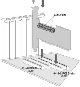
Step 3. Install the PCI RAID Cards
To install the SATA RAID controller remove the mounting screw and existing bracket from the rear panel behind the selected PCI
slot. Align the gold-fingered edge on the card with the selected PCI expansion slot. Press gently but firmly down to ensure that the
card is properly seated in the slot, as shown in Figure 2-11. Next, screw the bracket into the computer chassis. ARC-11xx controllers
can fit in both PCI (32-bit/3.3V) and PCI-X slots. It can get the best
performance installed in a 64-bit/133MHz PCI-X slot. ARC-12xx controllers require a PCI-Express x8 slot.
HARDWARE INSTALLATION
Step 4. Mount the Cages or Drives
Remove the front bezel from the computer chassis and install the cages or SATA Drives in the computer chassis. Loading drives to the drive tray if cages are installed. Be sure that the power is con-nected to either the cage backplane or the individual drives.
Figure 2-12, Mount Cages & Drives
HARDWARE INSTALLATION
Step 5. Connect the SATA Cable
Model ARC-11XX and ARC-12XX controllers have dual-layer SATA internal connectors. If you have not yet connected your SATA cables, use the cables included with your kit to connect the control-ler to the SATA hard drives.
The cable connectors are all identical, so it does not matter which end you connect to your controller, SATA hard drive, or cage back-plane SATA connector.
Figure 2-13, SATA Cable
Note:
The SATA cable connectors must match your HDD cage. For example: Channel 1 of RAID Card connects to channel 1 of HDD cage, channel 2 of RAID Card connects to channel 2 of HDD cage, and follow this rule.
Step 5-2. Connect the Multi-lance Cable
Model ARC-11XXML has multi-lance internal connectors, each of them can support up to four SATA drives. These adapters can be installed in a server RAID enclosure with a Multi-lance connector (SFF-8470) backplane. Multi-lance cables are not included in the ARC-11XXML package.
If you have not yet connected your Multi-lance cables, use the cables included with your enclosure to connect your controller to the Multi-lance connector backplane. This type of cable will depend on what enclosure you have. The following diagram shows one ex-ample picture of Multi-lane cable.
Unpack and remove the PCI RAID cards. Inspect it carefully. If any-thing is missing or damaged, contact your local dealer.
HARDWARE INSTALLATION
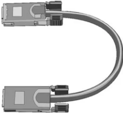
Step 5-3. Connect the Min SAS 4i to 4*SATA Cable
Model ARC-1231ML/1261ML/1280ML have Min SAS 4i (SFF-8087) internal connectors, each of them can support up to four SATA drives. These adapters can be installed in a server RAID enclosure with a standard SATA connector backplane. Min SAS 4i to SATA cables are included in the ARC-1231ML/1261ML/1280ML package. The following diagram shows the picture of MinSAS 4i to 4*SATA cables.
Unpack and remove the PCI RAID cards. Inspect it carefully. If anything is missing or damaged, contact your local dealer.
For sideband cable signal Please refer to page 37 for SGPIO bus. Figure 2-15, Min SAS 4i to 4*SATA Cable
HARDWARE INSTALLATION
Figure 2-16, Min SAS 4i to Multi-lance Cable
Step 5-4. Connect the Min SAS 4i to Multi-lance Cable Model ARC-1231ML/1261ML/1280ML have Min SAS 4i internal connectors, each of them can support up to four SATA drives. These controllers can be installed in a server RAID enclosure with a Multi-lance connector (SFF-8470) backplane. Multi-Multi-lance cables are not included in the ARC-12XXML package.
If you have not yet connected your Min SAS 4i to Multi-lance
cables, buy the Min SAS 4i to Multi-lance cables to fit your
enclosure. And connect your controller to the Multi-lance connector backplane. The type of cable will depend on what enclosure you have. The following diagram shows one example picture of Min SAS 4i to Multi-lance cable.
Unpack and remove the PCI RAID cards. Inspect it carefully. If anything is missing or damaged, contact your local dealer.
Step 5-5. Connect the Min SAS 4i to Min SAS 4i Cable
Model ARC-1231ML/1261ML/1280ML have Min SAS 4i (SFF-8087) internal connectors, each of them can support up to four SATA drives and SGPIO (Serial General Purpose Input/Output) side-band signals . These adapters can be installed in a server RAID enclosure with a Min SAS 4i internal connector backplane. Min SAS 4i cables are not included in the ARC-12XXML package.
This Min SAS 4i cable has eight signal pins to support four SATA drives and six pins for the SGPIO (Serial General Purpose Input/
Output) side-band signals. The SGPIO bus is used for efficient LED
management and for sensing drive Locate status. Please see page 52 for the details of the SGPIO bus.
HARDWARE INSTALLATION
Figure 2-17, Min SAS 4i to Min SAS 4i Cable
• Min SAS 4i Connector (SFF-8087) Signal
Name Pin Name Pin
HDD R0+ A2 HDD T0+ B2 HDD R0- A3 HDD T0- B3 HDD R1+ A5 HDD T1+ B5 HDD R1- A6 HDD T1- B6 Sideband 0 A8 Sideband 7 B8 Sideband 1 A9 Sideband 3 B9
Sideband 2 A10 Sideband 4 B10
Sideband 6 A11 Sideband 5 B11
HDD R2+ A13 HDD T2+ B13
HDD R2- A14 HDD T2- B14
Figure 2-18, Min SAS 4i (SFF-8087) Connector
The SGPIO signal can carry the fault/activity signal without needing any individual LED cable. The SGPIO is included in the SFF-8087.
HARDWARE INSTALLATION
Table-1 Min SAS 4i cable(SFF8087) pin assignment
Figure 2-19, Min SAS 4x to Min SAS 4x Cable
HDD R3+ A16 HDD T3+ B16
HDD R3- A17 HDD T3- B17
GND A1, A4, A7, A12, A15, A18 GND B1, B4, B7, B12, B15, B18
Step 5-6. Connect the Min SAS 4x to Min SAS 4x Cable
Model ARC-12X0ML/12X1ML have external Min SAS 4x (SFF-8088) connectors, each of them can support up to four SATA drives. These adapters can be installed in a server which works with external RAID enclosure with a Min SAS 4x connector. External Min SAS 4x cables are not included in the ARC-12X0ML/12X1ML package.
If you have not connected your Min SAS 4x cables yet, use the cables included with your enclosure to connect your controller to the Min SAS 4x connector. This type of cable will depend on what enclosure you have. The above diagram shows one example picture of Min SAS 4x cable.
Step 6. Install the LED Cable (optional)
ARC-1XXX Series Fault/Activity Header Intelligent Electronics Schematic.
HARDWARE INSTALLATION
Note:
A cable for the global indicator comes with your computer system. Cables for the individual drive LEDs may come with a drive cage or you may need to purchase them.
The intelligent LED controller outputs a low-level pulse to deter-mine if status LEDs are attached to pin sets 1 and 2. This allows
automatic controller configuration of the LED output. If the logi
-cal level is different between the fist 2 sets of the HDD LED header
(LED attached to Set 1 but not Set 2), the controller will assign the
first HDD LED header as the global indicator connector. Otherwise,
each LED output will show only individual drive status.
The SATA RAID controller provides four kinds of LED status connec-tors.
A: Global indicator connector, which light up when any drive is ac-tive.
B: Individual LED indicator connector, for each drive channel. C: I2C connector, for SATA proprietary backplane enclosure. D: SGPIO connector for SAS backplane enclosure
The following diagrams and description describes each type of con-nector.
HARDWARE INSTALLATION
Figure 2-20, ARC-1110/1120/1210/1220 global LED connection for computer case. A: Global indicator connector
If the system use only a single global indicator, attach the global indicator cable to the two pins HDD LED connector. The following diagrams show the connector and pin locations.
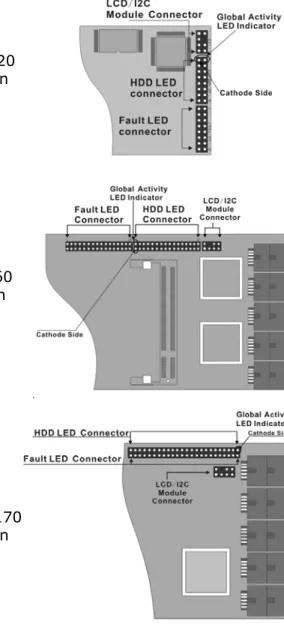
Figure 2-21, ARC-1130/1160/1230/1260 global LED connection for computer case.
Figure 2-22, ARC-1170 global LED connection for computer case.
HARDWARE INSTALLATION
Figure 2-23, ARC-1280 global LED connection for computer case.
Figure 2-24, ARC-1231ML/ 1261ML/1280ML global LED connection for computer case.
Figure 2-25, ARC-1201 LED connection for com-puter case.
HARDWARE INSTALLATION
LED Normal Status Problem Indication
Activity LED When the activity LED is illu-minated, there is I/O activity on that disk drive. When the LED is dark, there is no activ-ity on that disk drive.
N/A
Fault LED When the fault LED is solid illuminated, there is no disk present and When the fault LED is off, that disk is pres-ent and status is normal. When the "Identify Drive" is selected, the selected drive fault LED will blank.
When the fault LED is slow blink-ing (2 times/sec), that indicate disk drive has failed and should be hot-swapped immediately. When the activity LED is illumi-nated and fault LED is fast blinking (10 times/sec) that indicate there is rebuilding activity on the disk drive.
B: Individual LED indicator connector
Connect the cables for the drive activity LEDs and fault LEDs be-tween the backplane of the cage and the respective connector on the SATA RAID controller. The following describes the fault/activity LED.
Figure 2-26, ARC-1110/1120/1210/1220 individual LED indica-tors connector, for each channel drive.
HARDWARE INSTALLATION
Figure 2-27, ARC-1130/1160/1230/1260 individual LED indica-tors connector, for each channel drive.
Figure 2-28, ARC-1170 individual LED indicators connector, for each chan-nel drive.
Figure 2-29, ARC-1280 individual LED indicators connector, for each chan-nel drive.
HARDWARE INSTALLATION
Figure 2-30, ARC-1231ML/ 1261ML/1280ML individual LED indicators connector, for each channel drive.
Figure 2-31, ARC-1201 individual LED indicators connector, for each channel drive.
C: I2C Connector
You can also connect the I2C interface to a SATA backplane enclo-sure which includes Areca CPLD decoder controller on the back-plane. This can reduce the number of activity LED and/or fault LED cables. The I2C interface can also cascade to another SATA backplane enclosure for the additional channel status display.
HARDWARE INSTALLATION
Figure 2-32, Activity/Fault LED I2C connector connected between SATA RAID controller & SATA HDD cage backplane.
Figure 2-33, Activity/Fault LED I2C connector connected between SATA RAID controller & 4 SATA HDD backplane.
Note:
Ci-Design has supported this feature in its 4-port 12-6336-05A SATA ll backplane.
The following is the I2C signal name description for LCD & fault/ac-tivity LED.
HARDWARE INSTALLATION
PIN Description PIN Description
1 power (+5V) 2 GND
3 LCD Module Interrupt 4 Protective Key 5 LCD Module Serial Data 6 Fault/Activity clock 7 Fault/Activity Serial Data 8 LCD Module clock D: SGPIO bus
The preferred I/O connector for server backplanes is the Min SAS 4i (SFF-8087) internal serial-attachment connector. This connector has eight signal pins to support four SATA drives and six pins for the SGPIO (Serial General Purpose Input/Output) sideband signals which use to replace the individual LED cable.
The SGPIO bus is used for efficient LED management and for sensing drive locate status. See SFF 8485 for the specification of
the SGPIO bus.The number of drives supported can be increased, by a factor of four, by adding similar backplane to maximum of 24 drives (6 backplanes)
LED Management: The backplane may contain LEDs to indicate drive status. Light from the LEDs could be transmitted to the out-side of the server by using light pipes mounted on the SATA drive tray. A small CPLD on the backplane, connected via the SGPIO bus to a ARC-1231ML/1261ML/1280ML SATA RAID controller, could control the LEDs. Activity: blinking/controller access Fault: solid illuminated
Drive Locate Circuitry: The locate of a drive may be detected by sensing the voltage level of one of the pre-charge pins before and after a drive is installed. Fault blinking 2 times/second.
The following signal defines the SGPIO assignments for the Min
HARDWARE INSTALLATION
PIN Description PIN Description
SideBand0 SClock (Clock signal) SideBand1 SLoad (Last clock of a bit stream)
SideBand2 Ground SideBand3 Ground
SideBand4 SDataOut (Serial data output bit stream)
SideBand5 SDataIn (Serial data input bit stream)
SideBand6 Reserved SideBand7 Reserved
The following signal defines the sideband connector which can
work with Areca sideband cable on its SFF-8087 to 4 SATA cable. The sideband header is located at backplane. For SGPIO to work properly, please connect Areca 8-pin sideband cable to the
sideband header as shown above. See the table for pin definitions.
Step 7. Re-check the SATA HDD LED and Fault LED Cable Connections
Be sure that the proper failed drive channel information is dis-played by the fault and HDD activity LEDs. An improper connection will tell the user to ‘‘Hot Swap’’ the wrong drive. This will remove the wrong disk (one that is functioning properly) from the control-ler. This can result in failure and loss of system data.
Step 8. Power up the System
Check the installation thoroughly, reinstall the computer cover, and reconnect the power cord cables. Turn on the power switch at the rear of the computer (if equipped) and then press the power button at the front of the host computer.
HARDWARE INSTALLATION
Step 9. Configure Volume Set
The SATA RAID controller configures RAID functionality through the
McBIOS RAID manager. Please refer to Chapter 3, McBIOS RAID
manager, for the detail regarding configuration. The RAID controller can also be configured through the McRAID storage manager soft -ware utility with ArcHttp proxy server installed through on-board LAN port or LCD module. For this option, please refer to Chapter 6,
Web Browser-Based Configuration or LCD Configuration Menu.
Step 10. Install the Controller Driver For a new system:
• Driver installation usually takes places as part of operating sys-tem installation. Please refer to Chapter 4 Diver Installation for the detail installation procedure.
In an existing system:
• Install the controller driver into the existing operating system. Please refer to the Chapter 4, Driver Installation, for the detailed installation procedure.
Note:
For latest release versions of drivers, please download from http://www.areca.com.tw
Step 11. Install ArcHttp Proxy Server
The SATA RAID controller firmware has embedded the web-browser
McRAID storage manager. ArcHttp proxy server will enable it. The browser-based McRAID storage manager provides all of the cre-ation, management, and monitor SATA RAID controller status. Please refer to the Chapter 5 for the detail ArcHttp Proxy Server Installation. For SNMP agent function, please refer to Appendix C.
HARDWARE INSTALLATION
Configuration Utility Operating System Supported McBIOS RAID Manager OS-Independent
McRAID Storage Manager
(Via Archttp proxy server) Windows 2000/XP/2003, Linux, Free-BSD, Solaris and Mac SAP Monitor (Single Admin Portal to
scan for multiple RAID units in the net-work, Via ArcHttp proxy server)
Windows 2000/XP/2003
SNMP Manager Console Integration Windows 2000/XP/2003, Linux, Free-BSD
Step 12. Determining the Boot Sequences
The SATA RAID controller is a bootable controller. If your system already contains a bootable device with an installed operating tem, you can set up your system to boot a second operating sys-tem from the new controller. To add a second bootable controller, you may need to enter setup of M/B BIOS and change the device boot sequence so that the SATA RAID controller heads the list. If the system BIOS setup does not allow this change, your system
may not be configurable to allow the SATA RAID controller to act as
a second boot device.
Summary of the Installation
The flow chart below describes the installation procedures for SATA
RAID controller. These procedures include hardware installation,
the creation and configuration of a RAID volume through the Mc -BIOS/McRAID, OS installation and installation of SATA RAID con-troller software.
HARDWARE INSTALLATION
The software components configure and monitor the SATA RAID
controller via ArcHttp proxy server. McRAID Storage Manager
Before launching the firmware-embedded web server, McRAID stor -age man-ager, you can to install the ArcHttp proxy server on your server system or through on-board LAN-port (if equipped). If you need additional information about installation and start-up of this function, see the McRAID Storage Manager section in Chapter 6. SNMP Manager Console Integration
• Out of Band-Using Ethernet Port (12/16/24-port Control-ler)
Before launching the firmware-embedded SNMP agent in the sever, you need first to enable the fireware-embedded SNMP
agent function on your SATA RAID controller. If you need additional information about installation and start-up this function, see the section 6.8.4 SNMP Configuration
(12/16/24-port)
• In-Band-Using PCI-X/PCIe Bus (4/8/12/16/24-port Controller)
Before launching the SNMP agent in the sever, you need to
en-able the fireware-embedded SNMP community configuration first
and install Areca SNMP extension agent in your server system. If you need additional information about installation and start-up the function, see the SNMP Operation & Installation section in the Appendix C
Single Admin Portal (SAP) Monitor
This utility can scan for multiple RAID units on the network and monitor the controller set status. It also includes a disk stress test utility to identify marginal spec disks before putting the RAID unit into a production environment.
For additional information, see the utility manual in the packaged software CD or download it from the web site http://www.areca. com.tw
BIOS CONFIGURATION
3. McBIOS RAID Manager
The system mainboard BIOS automatically configures the following
SATA RAID controller parameters at power-up: • I/O Port Address
• Interrupt Channel (IRQ) • Adapter ROM Base Address
Use McBIOS RAID manager to further configure the SATA RAID con -troller to suit your server hardware and operating system.
3.1 Starting the McBIOS RAID Manager
This section explains how to use the McBIOS RAID manager to
configure your RAID system. The McBIOS RAID manager is de -signed to be user-friendly. It is a menu-driven program, residing
in the firmware, which allows you to scroll through various menus and sub-menus and select among the predetermined configuration
options.
When starting a system with an SATA RAID controller installed, it will display the following message on the monitor during the start-up sequence (after the system bios startstart-up screen but before the operating system boots):
The McBIOS RAID manager message remains on your screen for
about nine seconds, giving you time to start the configuration
menu by pressing Tab or F6. If you do not wish to enter configu -ration menu, press ESC to skip configuration immediately. When
activated, the McBIOS RAID manager appears showing a selection dialog box listing the SATA RAID controllers that are installed in the system.
The legend at the bottom of the screen shows you what keys are enabled for the screens.
I/O-Port=F3000000h, IRQ=11, BIOS ROM mapped at D000:0h No BIOS disk Found, RAID Controller BIOS not installed!
Press <Tab/F6> to enter SETUP menu. 9 second(s) left <ESC to Skip>..
ARC-1xxx RAID Ctrl - DRAM: 128(MB) / #Channels: 8 BIOS: V1.00 / Date: 2004-5-13 - F/W: V1.31 / Date: 2004-5-31
BIOS CONFIGURATION
Areca Technology Corporation RAID Controller Setup <V1.0, 2004/05/20>
ArrowKey Or AZ:Move Cursor, Enter: Select, ** Select & Press F10 to Reboot** Select An Adapter To Configure
( 3/14/ 0)I/O=DD200000h, IRQ = 9
Use the Up and Down arrow keys to select the adapter you want
to configure. While the desired adapter is highlighted, press the
Enter key to enter the main menu of the McBIOS RAID manager.
3.2 McBIOS RAID manager
The McBIOS RAID manager is firmware-based and is used to con
-figure RAID sets and volume sets. Because the utility resides in the SATA RAID controller firmware, operation is independent of any
operating systems on your computer. This utility can be used to: • Create RAID sets,
• Expand RAID sets, • Add physical drives,
• Define volume sets,
Controller I/O Port:F3000000h, F2: Select Controller, F10: Reboot System
ArrowKey Or AZ:Move Cursor, Enter: Select, ESC: Escape, L:Line Draw, X: Redraw Areca Technology Corporation RAID Controller
Main Menu Raid Set Function Volume Set Function Physical Drives Raid System Function Ethernet Configuration View System Events Clear Event Buffer Hardware Monitor System Information
Quick Volume/Raid Setup
Verify Password
Note:
The manufacture default password is set to 0000; this password can be modified by selecting Change Password in the Raid System Function section.BIOS CONFIGURATION
3.4 Designating Drives as Hot Spares
Any unused disk drive that is not part of a RAID set can be
desig-nated as a hot spare. The “Quick Volume/Raid Setup” configuration
will add the spare disk drive and automatically display the appro-priate RAID level from which the user can select. For the “Raid Set
Function” configuration option, the user can use the “Create Hot Spare” option to define the hot spare disk drive.
When a hot spare disk drive is being created using the “Create Hot Spare” option (in the “Raid Set Function”), all unused physical de-vices connected to the current controller appear:
Choose the target disk by selecting the appropriate check box. Press the Enter key to select a disk drive, and press Yes in the create hot spare to designate it as a hot spare.
• Modify volume sets,
• Modify RAID level/stripe size,
• Define pass-through disk drives,
• Modify system functions, and • Designate drives as hot spares.
3.3 Configuring Raid Sets and Volume Sets
You can configure RAID sets and volume sets with McBIOS RAID
manager automatically using “Quick Volume/Raid Setup” or
manu-ally using “Raid Set/Volume Set Function”. Each configuration method requires a different level of user input. The general flow of operations for RAID set and volume set configuration is:
Step Action
1 Designate hot spares/pass-through drives (optional). 2 Choose a configuration method.
3 Create RAID sets using the available physical drives.
4 Define volume sets using the space available in the RAID Set.
5 Initialize the volume sets and use volume sets (as logical drives) in the host OS.
BIOS CONFIGURATION
3.5 Using Quick Volume/Raid Setup
Con-figuration
“Quick Volume/Raid Setup” configuration collects all available
drives and includes them in a RAID set. The RAID set you create is associated with exactly one volume set. You will only be able to modify the default RAID level, the stripe size, and the capacity of the new volume set. Designating drives as hot spares is also pos-sible in the RAID level selection option. The volume set default settings will be:
Parameter Setting
Volume Name Volume Set # 00
SCSI Channel/SCSI ID/SCSI LUN 0/0/0
Cache Mode Write Back
Tag Queuing Yes
The default setting values can be changed after configuration
is completed. Follow the steps below to create arrays using the “Quick Volume/ Raid Setup” method:
Step Action
1 Choose “Quick Volume/Raid Setup” from the main menu. The available RAID levels with hot spare for the current volume set drive are displayed. 2 It is recommended that you use drives of the same capacity in a specific
array. If you use drives with different capacities in an array, all drives in the RAID set will be set to the capacity of the smallest drive in the RAID set.
The numbers of physical drives in a specific array determines which RAID
levels that can be implemented in the array. RAID 0 requires 1 or more physical drives. RAID 1 requires at least 2 physical drives. RAID 1+Spare requires at least 3 physical drives. RAID 10 requires at least 4 physical drives. RAID 3 requires at least 3 physical drives. RAID 5 requires at least 3 physical drives. RAID 3 +Spare requires at least 4 physical drives. RAID 5 + Spare requires at least 4 physical drives. RAID 6 requires at least 4 physical drives.
RAID 6 + Spare requires at least 5 physical drives.
Highlight the desired RAID level for the volume set and press the Enter
BIOS CONFIGURATION
3.6 Using RAID Set/Volume Set Function
Method
In “Raid Set Function”, you can use the “Create Raid Set Function” to generate a new RAID set. In “Volume Set Function”, you can use the “Create Volume Set” function to generate an associated
volume set and and configuration parameters.
If the current controller has unused physical devices connected, you can choose the “Create Hot Spare” option in the “Raid Set
Function” to define a global hot spare. Select this method to con
-figure new RAID sets and volume sets. The “Raid Set/Volume Set Function” configuration option allows you to associate volume sets
with partial and full RAID sets.
3 The capacity for the current volume set is entered after highlighting the desired RAID level and pressing the Enter key.
The capacity for the current volume set is displayed. Use the UP and DOWN arrow keys to set the capacity of the volume set and press the Enter key to confirm. The available stripe sizes for the current volume
set are then displayed.
4 Use the UP and DOWN arrow keys to select the current volume set stripe size and press the Enter key to confirm. This parameter speci
-fies the size of the stripes written to each disk in a RAID 0, 1, 10, 5 or
6 volume set. You can set the stripe size to 4 KB, 8 KB, 16 KB, 32 KB, 64 KB, or 128 KB. A larger stripe size provides better read performance, especially when the computer preforms mostly sequential reads. How-ever, if the computer preforms random read requests more often, choose a smaller stripe size.
5 When you are finished defining the volume set, press the Enter key to
confirm the “Quick Volume/Raid Setup” function.
6 Foreground (Fast Completion) Press Enter key to define Foreground
Initialization or Selected the Background (Instant Available) or No Init. In the Background Initialization, the initialization proceeds as a background task, the volume set is fully accessible for system reads and writes. The operating system can instantly access to the newly created arrays without requiring a reboot and waiting the initialization complete. In Foreground Initialization, the initialization proceeds must be completed before the volume set ready for system accesses. In No Init, there is no initialization on this volume.
7 Initialize the volume set you have just configured.
8 If you need to add additional volume set, using main menu “Create Vol-ume Set” function.
BIOS CONFIGURATION
Step Action
1 To setup the hot spare (option), choose “Raid Set Function” from the main menu. Select the “Create Hot Spare” and press the Enter key to
define the hot spare.
2 Choose “RAID Set Function” from the main menu. Select “Create Raid Set” and press the Enter key.
3 The “Select a Drive For Raid Set” window is displayed showing the SATA drives connected to the SATA RAID controller.
4 Press the UP and DOWN arrow keys to select specific physical drives.
Press the Enter key to associate the selected physical drive with the cur-rent RAID set.
It is recommended that you drives of the same capacity in a specific
array. If you use drives with different capacities in an array, all drives in the RAID set will be set to the capacity of the smallest drive in the RAID
set. The numbers of physical drives in a specific array determines which
RAID levels that can be implemented in the array. RAID 0 requires 1 or more physical drives. RAID 1 requires at least 2 physical drives. RAID 10 requires at least 4 physical drives. RAID 3 requires at least 3 physical drives. RAID 5 requires at least 3 physical drives. RAID 6 requires at least 4 physical drives.
5 After adding the desired physical drives to the current RAID set, press Yes to confirm the “Create Raid Set” function.
6 An “Edit The Raid Set Name” dialog box appears. Enter 1 to 15
alphanu-meric characters to define a unique identifier for this new raid set. The
default raid set name will always appear as Raid Set. #. Press Enter to
finish the name editing.
7 Press the Enter key when you are finished creating the current RAID set. To continue defining another RAID set, repeat step 3. To begin vol
-ume set configuration, go to step 8.
8 Choose the “Volume Set Function” from the main menu. Select “Create Volume Set” and press the Enter key.
9 Choose a RAID set from the “Create Volume From Raid Set” window. Press the Enter key to confirm the selection.
10 Choosing Foreground (Fast Completion) or Background (Instant Avail-ability) initialization or No Init (To Rescue Volume): during Background Initialization, the initialization proceeds as a background task and the volume set is fully accessible for system reads and writes. The operating system can instantly access the newly created arrays without requiring a reboot and waiting for initialization complete. In Foreground Initializa-tion, the initialization must be completed before the volume set is ready for system accesses. In Fast Initialization, initiation is completed more quickly but volume access by the operating system is delayed. When No Init, there is no initialization on this volume.
BIOS CONFIGURATION
3.7 Main Menu
The main menu shows all functions that are available for executing actions, which is accomplished by clicking on the appropriate link.
Note:
The “Modify Volume Set” method provides the same
func-tions as the “Create Volume Set” configuration method. In the
“Volume Set function”, you can use “Modify Volume Set” to change all volume set parameters except for capacity (size).
Controller I/O Port:F3000000h, F2: Select Controller, F10: Reboot System
ArrowKey Or AZ:Move Cursor, Enter: Select, ESC: Escape, L:Line Draw, X: Redraw Areca Technology Corporation RAID Controller
Main Menu Raid Set Function Volume Set Function Physical Drives Raid System Function Ethernet Configuration View System Events Clear Event Buffer Hardware Monitor System Information
Quick Volume/Raid Setup
Verify Password
Note:
The manufacture default password is set to 0000; this password can be modified by selecting Change Password in the Raid System Function section.Option Description
Quick Volume/Raid Setup Create a default configuration based on the number of
physical disk installed Raid Set Function Create a customized RAID set Volume Set Function Create a customized volume set Physical Drives View individual disk information Raid System Function Setup the RAID system configuration Ethernet Configuration Ethernet LAN setting (12/16/24 ports only) View System Events Record all system events in the buffer Clear Event Buffer Clear all information in the event buffer Hardware Monitor Show the hardware system environment status System Information View the controller system information
11 If space remains in the raid set, the next volume set can be configured. Repeat steps 8 to 10 to configure another volume set.
BIOS CONFIGURATION
This password option allows user to set or clear the RAID control-ler’s password protection feature. Once the password has been
set, the user can only monitor and configure the raid controller by
providing the correct password. The password is used to protect the internal RAID controller from unauthorized entry. The control-ler will only prompt for the password when entering the main menu from the initial screen. The SATA RAID controller will automatically return to the initial screen when it does not receive any command in twenty seconds.
3.7.1 Quick Volume/RAID Setup
“Quick Volume/RAID Setup” is the fastest way to prepare a RAID set and volume set. It requires only a few keystrokes to com-plete. Although disk drives of different capacity may be used in the RAID set, it will use the capacity of the smallest disk drive as the capacity of all disk drives in the RAID set. The “Quick Vol-ume/RAID Setup” option creates a RAID set with the following properties:
1. All of the physical drives are contained in one RAID set. 2. The RAID level, hot spare, capacity, and stripe size options
are selected during the configuration process.
3. When a single volume set is created, it can consume all or a portion of the available disk capacity in this RAID set.
4. If you need to add an additional volume set, use the main menu “Create Volume Set” function.
The total number of physical drives in a specific RAID set deter -mine the RAID levels that can be implemented within the RAID
Controller I/O Port:F3000000h, F2: Select Controller, F10: Reboot System
ArrowKey Or AZ:Move Cursor, Enter: Select, ESC: Escape, L:Line Draw, X: Redraw Areca Technology Corporation RAID Controller
Main Menu Raid Set Function Volume Set Function Physical Drives Raid System Function Ethernet Configuration View System Events Clear Event Buffer Hardware Monitor System Information
Quick Volume/Raid Setup
Total 4 Drives Raid 0 Raid 1 + 0 Raid 1 + 0 + Spare Raid 3 Raid 5 Raid 3 + Spare Raid 5 + Spare Raid 6
BIOS CONFIGURATION
Set. Select “Quick Volume/RAID Setup” from the main menu; all possible RAID level will be displayed on the screen.
If volume capacity will exceed 2TB, controller will show the “Greater Two TB Volume Support” sub-menu.
Controller I/O Port:F3000000h, F2: Select Controller, F10: Reboot System
ArrowKey Or AZ:Move Cursor, Enter: Select, ESC: Escape, L:Line Draw, X: Redraw Areca Technology Corporation RAID Controller
Main Menu Raid Set Function Volume Set Function Physical Drives Raid System Function Ethernet Configuration View System Events Clear Event Buffer Hardware Monitor System Information
Quick Volume/Raid Setup
Total 4 Drives Raid 0 Raid 1 + 0 Raid 1 + 0 + Spare Raid 3 Raid 5 Raid 3 + Spare Raid 5 + Spare Raid 6
Greater Two TB Volume Support No
Use 64bit LBA For Windows For Windows
• No
It keeps the volume size with max. 2TB limitation. • LBA 64
This option use 16 bytes CDB instead of 10 bytes. The maximum volume capacity supports up to 512TB.
This option works on different OS which supports 16 bytes CDB. Such as:
Windows 2003 with SP1 Linux kernel 2.6.x or latter • For Windows
It change the sector size from default 512 Bytes to 4k Bytes. the maximum volume capacity up to 16TB.
This option works under Windows platform only. And it can not be converted to “Dynamic Disk”, because 4k sector size is not a standard format.
For more details please download PDF file from ftp://ftp.areca. com.tw/RaidCards/Documents/Manual_Spec/Over2TB_ 050721.zip
BIOS CONFIGURATION
Stripe Size This parameter sets the size of the stripe written to each disk in a RAID 0, 1, 10, 5, or 6 logical drive. You can set the stripe size to 4 KB, 8 KB, 16 KB, 32 KB, 64 KB, or 128 KB.
A larger stripe size produces better-read performance, especially if your computer does mostly sequential reads. However, if you A single volume set is created and consumes all or a portion of
the disk capacity available in this RAID set. Define the capacity of
volume set in the “Available Capacity” popup. The default value for the volume set, which is 100% of the available capacity, is displayed in the selected capacity. Use the UP and DOWN keys to select the capacity, press the Enter key to accept this value. If the volume set uses only part of the RAID set capacity, you can use the “Create Volume Set” option in the main menu to define
additional volume sets.
Controller I/O Port:F3000000h, F2: Select Controller, F10: Reboot System
ArrowKey Or AZ:Move Cursor, Enter: Select, ESC: Escape, L:Line Draw, X: Redraw Areca Technology Corporation RAID Controller
Main Menu Raid Set Function Volume Set Function Physical Drives Raid System Function Ethernet Configuration View System Events Clear Event Buffer Hardware Monitor System Information
Quick Volume/Raid Setup
Total 4 Drives Raid 0 Raid 1 + 0 Raid 1 + 0 + Spare Raid 3 Raid 5 Raid 3 + Spare Raid 5 + Spare Raid 6 Available Capacity : 160.1GB Selected Capacity : 160.1GB
Select Strip Size 4K 8K 16K 32K 128K 64K
Controller I/O Port:F3000000h, F2: Select Controller, F10: Reboot System
ArrowKey Or AZ:Move Cursor, Enter: Select, ESC: Escape, L:Line Draw, X: Redraw Areca Technology Corporation RAID Controller
Main Menu Raid Set Function Volume Set Function Physical Drives Raid System Function Ethernet Configuration View System Events Clear Event Buffer Hardware Monitor System Information
Quick Volume/Raid Setup
Total 4 Drives Raid 0 Raid 1 + 0 Raid 1 + 0 + Spare Raid 3 Raid 5 Raid 3 + Spare Raid 5 + Spare Raid 6 Available Capacity : 160.1GB Selected Capacity : 160.1GB
BIOS CONFIGURATION
3.7.2 Raid Set Function
Manual configuration gives complete control of the RAID set set
-ting, but it will take longer to configure than “Quick Volume/Raid Setup” configuration. Select “Raid Set Function” to manually con
-figure the RAID set for the first time or delete existing RAID sets and reconfigure the RAID set.
Controller I/O Port:F3000000h, F2: Select Controller, F10: Reboot System
ArrowKey Or AZ:Move Cursor, Enter: Select, ESC: Escape, L:Line Draw, X: Redraw Areca Technology Corporation RAID Controller
Main Menu Raid Set Function Volume Set Function Physical Drives Raid System Function Ethernet Configuration View System Events Clear Event Buffer Hardware Monitor System Information
Quick Volume/Raid Setup
Total 4 Drives Raid 0 Raid 1 + 0 Raid 1 + 0 + Spare Raid 3 Raid 5 Raid 3 + Spare Raid 5 + Spare Raid 6 Available Capacity : 160.1GB Selected Capacity : 160.1GB
Select Strip Size 4K 8K 16K 32K 128K 64K
Create Vol/Raid Set No
Yes
Controller I/O Port:F3000000h, F2: Sel “Noect Controller, F10: Reboot System
ArrowKey Or AZ:Move Cursor, Enter: Select, ESC: Escape, L:Line Draw, X: Redraw Areca Technology Corporation RAID Controller
Create Vol/Raid Set No
Yes
Main Menu Raid Set Function Volume Set Function Physical Drives Raid System Function Ethernet Configuration View System Events Clear Event Buffer Hardware Monitor System Information
Quick Volume/Raid Setup
Total 4 Drives Raid 0 Raid 1 + 0 Raid 1 + 0 + Spare Raid 3 Raid 5 Raid 3 + Spare Raid 5 + Spare Raid 6 Available Capacity : 160.1GB Selected Capacity : 160.1GB
Select Strip Size 4K 8K 16K 32K 128K 64K Initialization Mode Background (Instant Available)
No Init (To Rescue Volume)
Foreground (Faster Completion)
are certain that your computer performs random reads more of-ten, select a smaller stripe size.
Press the Yes option in the “Create Vol/Raid Set” dialog box, the RAID set and volume set will start to initialize it.
Select “Foreground (Faster Completion)” or “Background (Instant Available)” for initialization. “No Init (To Rescue Volume)” for
BIOS CONFIGURATION
Controller I/O Port:F3000000h, F2: Select Controller, F10: Reboot System
ArrowKey Or AZ:Move Cursor, Enter: Select, ESC: Escape, L:Line Draw, X: Redraw Areca Technology Corporation RAID Controller
Main Menu
Quick Volume/Raid Setup Volume Set Function Physical Drives Raid System Function Ethernet Configuration View System Events Clear Event Buffer Hardware Monitor System Information
Raid Set Function
3.7.2.1 Create Raid Set
To define a RAID set, follow the procedure below:
1. Select “Raid Set Function” from the main menu.
2. Select “Create Raid Set “ from the “Raid Set Function” dialog box.
3. A “Select SATA Drive For Raid set” window is displayed showing the SATA drives connected to the current controller. Press the UP and DOWN arrow keys to select specific physical
drives. Press the Enter key to associate the selected physical drive with the current RAID set. Repeat this step; the user can add as many disk drives as are available to a single RAID set.
When finish selecting SATA drives for RAID set, press the Esc
key. A “Create Raid Set Confirmation” screen appears, select the
Yes option to confirm it.
Controller I/O Port:F3000000h, F2: Select Controller, F10: Reboot System
ArrowKey Or AZ:Move Cursor, Enter: Select, ESC: Escape, L:Line Draw, X: Redraw Areca Technology Corporation RAID Controller
Main Menu
Quick Volume/Raid Setup Volume Set Function Physical Drives Raid System Function Ethernet Configuration View System Events Clear Event Buffer Hardware Monitor System Information
Raid Set Function
Raid Set Function Delete Raid Set Expand Raid Set Activate Raid Set Create Hot Spare Delete Hot Spare Raid Set Information
Create Raid Set
Select IDE Drives For Raid Set [ ]Ch04| 80.0GBST380013AS [ ]Ch05| 80.0GBST380013AS [ ]Ch08| 80.0GBST380013AS