REDUCTION OF HARMONIC EXPLOITATION DSP
CONTROLLER BASED SHUNT ACTIVE FILTER
FOR PEMFC FED NON-LINEAR LOAD
K. Hemachandran1, T. Balaji1, B. Rajesh1, Santhosh Yadav1, B. Justus Rabi2 and S. S.Darly3
1Dr. MGR Educational and Research Institute University, Chennai, India 2Shri Andal Alagar College of Engineering, Mamandur, India
3University College of Engineering Thindivanam, India
E-Mail: [email protected]
ABSTRACT
In this paper the Total Harmonic Distortion is reduced using a DSP based shunt active power filter with Proton Exchange Membrane Fuel cell for a three phase three wire system with nonlinear load. In this APF is connected in parallel with nonlinear load as an equivalent conductance technique is carried out. The concept of using Shunt Active Power Filter is to mitigate harmonics and to compensate reactive power. By using TMS320F2812eZdsp, PWM signals have been generated accurately for controlling the switching of the insulated gate bipolar transistor (IGBT’s) in the CC-VSI to make the compensated source current sinusoidal and in-phase with the source voltage. A self charging technique is used to regulate the DC-Link capacitor voltage to a desired level. The proposed controller is realized under MATLAB simulink and the THD is analyzed using FFT.
Keywords: current harmonics, digital signal processor (DSP), PEMFC, shunt active power filter.
1. INTRODUCTION
The utilization of alternating current circuits in electrical power systems has been a typical practice subsequent to the beginning of the interconnected power system. Far reaching utilization of power electronic circuits for vitality molding builds the reactive current as well as produce critical current harmonics offering ascent to non-sinusoidal current and voltage waveforms. The expanded reactive power, non-sinusoidal supply voltage and current, and unbalance in power conveyance system result in numerous unfriendly impacts, for example, overheating of appropriation transformers, poor system productivity, precariousness, unsettling influence to different purchasers and obstruction with exactness instrument and communication equipments and so on.
Customarily, shunt passive filters were utilized to mitigate harmonics; however the latent filters have the faults of altered remuneration, expansive size, and reverberation [3]. To overcome previously stated issues, the shunt dynamic power filters shows up as the dynamic arrangement most appropriate for the pay necessities. The guideline of operation of the shunt dynamic filter is to supply the undesired harmonics and reactive power to the load, so that the mains current is of enhanced quality. The majority of the APFs outlined so far are in light of immediate reactive power (p-q) theory, modified p-q theory and synchronous reference frame theory. In these strategies, utility voltage and burden streams are initially changed in two-pivot representation and reference current are likewise registered in two-hub network [4, 5]. The greater part of these controllers require an expansive number of changes, more quantities of sensors and thus their execution give off an impression of being convoluted
for low and medium power applications. Likewise, in the vast majority of these procedures, the mains voltages are expected as a perfect source. In any case, actually, the mains voltages are frequently misshaped in numerous modern applications which influence the remuneration's precision current accordingly the critical decay in the execution of the SAPFs [11, 13].
Some more procedures are accessible which don't oblige detecting of the harmonics or reactive power prerequisite at the heap end for remuneration of unequal, distorted currents utilizing SAPFs. The idea of keeping up comparable distortion in the remunerating current, as present in the mains voltage is reported in the literature [16]. As of late, digital signal processors (DSP) are being utilized as a part of the greater part of the application and oblige refined control. DSP-based control for dynamic power filters have been accounted for in a few papers in which universally useful and floating point DSPs are utilized [1].
successful control furthermore; this fixed point eZdsp gives a less complex and less expensive arrangement. The system description is depicted below to demonstrate the viability of the proposed algorithm.
2. SYSTEM DESCRIPTION AND CONTROL
2.1 Power circuit
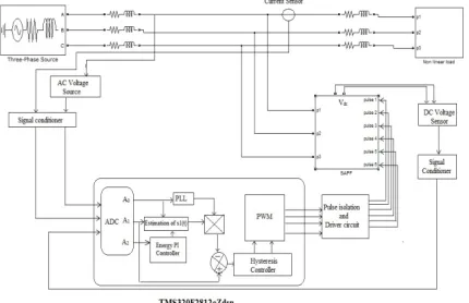
[image:2.612.329.531.95.210.2]A schematic chart of the created DSP based current controlled three-phase shunt APF system for current harmonics for sinusoidal supply voltage is indicated in Figure-1.
Figure-1. DSP based three phase shunt active power filter
scheme.
It comprises of a three-phase voltage source (sinusoidal) supplying energy to nonlinear load and a current controlled three-phase active power filter associated in parallel with the nonlinear load. The filter comprises of an inductor Lc, and resistance RC (proportionate resistance of the inverter loss, the inductance loss, and the circuit loss) and a three-phase IGBT span CC-VSI. A smoothing inductor (series passive filter) Lsm is associated in arrangement with joined load [1]. A transporter less hysteresis controller is utilized for heartbeats era, which is connected to the switches, joined in CC-VSI circuit to infuse a compensating current. A TMS320F2812 (32 bit, 150 MIP) fixed point digital signal processor is utilized for era of suitable heartbeats for IGBTs control [1].
2.2 Control circuit
The three major sections, PLL, Energy PI controller and hysteresis controller of the proposed control algorithm for active power filter [11, 12].
Figure-2(a). Control scheme based on LPF.
Figure-2(b). Control scheme based on PLL.
2.3 Phase-Lock Loop (PLL)
In the most mechanical environment, utility voltage is regularly distorted and all things considered mains voltage mutilation influences the filter execution. In general, to make the mains voltage mutilation less, either PLL or LPF are utilized. Utilizing equation (1)
is(t) = Gc. vs (t) = Gc Vs1(t)sin(wt) (1)
For coveted source current estimation, LPF is obliged to channel the source voltage and if equation (2)
is(t) = Is1(t) sin(wt) (2)
Is utilized for reference current estimation, then PLL is required for obliged unit sine format era. The control plan in view of LPF and PLL are demonstrated in Figure 2(a) and 2(b) individually. In this paper PLL methodology is utilized for reference source current era [1]. The instantaneous source voltage connected to the PLL results is a mutilation less unit sine format of fundamental frequency [6, 14].
2.4 Energy PI controller
[image:2.612.331.534.244.360.2] [image:2.612.79.294.249.388.2]voltage fluctuation on the dc-link capacitor must be kept away from. To manage the dc-link voltage, conventionally PI controllers are utilized. The dynamic response of traditional PI control amid transient is moderate. Likewise the configuration of PI controller parameters is fairly troublesome for a complex system and thus basically these parameters are chosen by experimentation.
To conquer the inconvenience of routine PI controller, a vitality based discrete PI controller is proposed here1. To direct the dc-link capacitor voltage at
the sought level, an extra real power has been drawn by the PEMFC source to charge the capacitor. The vitality (Edc) needed by the dc-link capacitor to charge the
capacitor from real (Vdc) to the reference voltage (Vdcref)
can be communicated as
Edc= 1/2 Cdc (V2dref - V2dc) (3)
2.5 Hysteresis controller and injection circuit
Hysteresis controller is utilized as a part of the proposed plan to adjust the CC- VSI with PEMFC. The determined numerical mathematical statement
ic(t) = iL(t)-i*s(t) = iLfq + iLh =Δis (4)
Is utilized to compute the actual signal Δis= ic(t) =
iL(t)-i*s(t) for the hysteresis controller. This Δis signal
continues in the hysteresis controller, and taking into account the estimation of Δis the hysteresis control will
switch the switches of the PWM converter. The yield mathematical statement will be
Sw = hys (ic(t) = Δis) = 1 if Δis > b
0 if Δis < -b (5)
For every stage the two-level PWM-voltage source inverter system of the hysteresis current controller are used autonomously. The exchanging sign of the three stages is created straightforwardly by current controller. The error current is the distinction between the wanted reference current iref (t) and the real source current i actual (t). If the slip current surpasses the upper hysteresis band limit (+h), the upper switch of the inverter arm gets to be OFF and the lower switch gets to be ON [4, 15].
The exchanging rationale of HCC is figured as takes after:
In the event that δ >HB upper switch is OFF (S1=0) and lower switch is ON (S4=1).
In the event that δ <-HB upper switch is ON (S1=1) and lower switch is OFF (S4=0).
Where δ is the distinction between burden current and reference current. The exchanging rationale for stage b and stage c is like stage an, utilizing comparing reference and measured streams and hysteresis transfer speed (HB) and is demonstrated in Figure-3.
Figure-3. Hysteresis current controllers.
2.6 Algorithm steps
The fundamental strides of the proposed Algorithm are as per the following.
Step 1: Estimation of crest estimations of key
part of source voltage and load current.
Step 2: Estimation of active loss fundamental
component of source current Isl (t) utilizing vitality PI
controller.
Step 3: Estimation of proportionate conductance
GC and crest estimation of reference source current Is1 (t)
utilizing (2)
Step 4: Filtration of mutilated source voltage and
unit vector era utilizing PLL.
Step 5: Reference source current assessment by
duplicating yields of step3 and step4.
Step 6: Estimation of APF pay current by
contrasting reference source current and actual load current.
Step 7: To produce the suitable gate pulses by
applying the yield of step6 to hysteresis controller [7] and [8].
3. MATLAB BASED SIMULATION
3.1 System parameters
The simulation of three phase active power filter is applied with the system parameters shown within the Table-1.
Table-1. System parameters.
Components Range
Line voltage 440V Supply Frequency 50Hz Source Impedance (resistance,
inductance) 1Ω, .1mH Non-linear load (resistance,
inductance) 10Ω, 100mH Filter impedance (resistance,
inductance) 1Ω, 2.5mH DC side capacitance 1400µf
The supply to the system includes of a PEM fuel cell, a DC to DC boost converter and a three phase voltage supply electrical converter. The supply current is distorted owing to nonlinear rectifier load. The TMS320F2812eZdsp controller uses energy PI controller internally to keep up the capacitance voltage constant. The iteration methodology is chosen to search out the membership values of the energy PI controller and therefore the needed performance is achieved. An occasional Low pass filter is employed for eliminating higher order harmonics9. A PLL is an associate degree
electronic circuit consisting of a variable frequency generator and a section detector, that generates associate degree output whose section is expounded to the section of associate degree input reference signal. A section detector compares the two input signals and generates miscalculation signal proportional to their section distinction. The error signal is filtered associate degree given to drive a Voltage Controlled generator (VCO) to make an output section. This output is once more fed back to the input through a possible divider [2, 4, 5].If the output section drifts, it will increase the error signal and drives the VCO introduce the other direction to cut back the error and to get the reference signal. TMS320F2812eZdsp controller with shunt active power filter is simulated with a supply voltage of 440 volts, supply resistance of one ohm, resistivity of 0.1mH for a rectifier load that is very non-linear and is shown in Figure-4.
Figure-4. Simulation of SAPF with DSP controller.
3.2 Results
The source current waveform is distorted by the harmonics produced due to the rectifier load without filter and is shown in Figure-5.
Figure-5. Source current before compensation.
The reference current output from the energy PI controller block with reduced harmonics and frequency of 50 Hz is employed for comparison with load current to produce error input to HCC [10]. The reference current generated largely depends on the DC capacitor voltage, load current and PLL operation. The compensating output current of the electrical converter is shown in Figure-6. The most peak worth of 30A compensating current is given by the electrical converter to the PCC and therefore the quantity of current fed to the PCC depends directly on the harmonics from the load and PWM pulses from the HCC block [4], [9].
Figure-6. Compensating current.
The source current when compensation mistreatment APF is shown within the Figure-7 severally. The source current nearly resembles a wave with reduced harmonics.
3.3 THD analysis
In this three phase system the THD analysis of source current is analyzed by FFT [12] is shown in Figure-8.
Figure-8. THD analysis of source current without DSP
controller with SAPF.
The THD analysis of the source current with compensation using APF reduced significantly from 62.45% to 12.32% as shown in Figure-9.
Figure-9. THD analysis of source current with DSP
controller with SAPF.
The assessment of THDs for both the waveforms (for source current without DSP and SAPF and with DSP and SAPF) is shown in the Table-2. The THD of source current increases a lot due to the odd order harmonics namely the 3rd, 5th and 7th order (56.58%, 16.81% and
15.02%, respectively). By using the DSP Controller with SAPF for compensating harmonics, the 3rd, 5th and 7th
order harmonics are reduced (8.48%, 6.49%and 4.65% respectively). Thus the THD for source current gets reduced significantly.
Table-2. THD of source current with and without DSP
controller and SAPF.
Harmonic order
THD (% of fundamental)
without SAPF
THD (% of fundamental)
with DSP controller with
SAPF
H3 56.58 8.48
H5 16.81 6.49
H7 15.28 4.65
H9 7.84 3.08
H11 7.22 1.91
4. CONCLUSIONS
The proposed control algorithm for the three phase shunt active power filter has been initial simulated then valid exploitation fixed point eZdsp. It is found that the SAPF will expeditiously eliminate the harmonics and additionally compensate the reactive power needed by the load leading to unity power factor load and sinusoidal source current. The relative reduction altogether the harmonic elements make sure the effectiveness of the proposed algorithms.
REFERENCES
[1] Gitanjali Mehta, Student Member, IEEE, R. D. Patidar and S. P. Singh. 2011. Member, IEEE. Design, Analysis and Implementation of DSP based Single-Phase Shunt Active Filter Controller. Emerging Trends in Electrical and Computer Technology (ICETECT). pp. 166-173.
[2] D. A.Torrey and A. M. Al-Zamel. 1995. Single-phase active power filters for multiple nonlinear loads. IEEE Transactions on Power Electronics. 10(3): 263-272.
[3] H. Akagi. 1996. New trends in active filters for power quality conditioning. IEEE Transactions on Industry Applications. 32(6): 1312-1322.
[4] K.Hemachandran, Dr.B.Justus Rabi and Dr.S.Darly. 2014. Mitigation of Harmonics using Active Shunt Filter with PEMFC, Asian Journal of Applied Sciences, (ISSN: 2321-0893), 02(06): 837-845.
[6] B. Singh, K. Al-Haddad and A. Chandra. 1999. A review of active power filters for power quality improvement. IEEE Transaction on Industrial Electronics. 46(5): 960-971.
[7] B. Singh, K. Al-Haddad and A. Chandra. 1998. A new control approach to three-phase active filter for harmonics and reactive power compensation. IEEE Transaction on Power Systems. 13(1): 133-138.
[8] Mehta.G, Singh S.P, Patidar R.D. 2011. Non-linear load compensation in fuel cell grid interfaced system using active power filter, at PEDS, IEEE Conference. ISSN: 2164-5256, pp. 197-202.
[9] Z. P. Fang, G.W. Ott, and D. J. Adams. 1998. Harmonics and reactive power compensation based on the generalized instantaneous reactive power theory for three-phase four-wire systems. IEEE Transactions on Power Electronics. 13(3): 1174-1181.
[10]S. Bhattacharya, D. M. Divan and B. Banerjee. 1991. Synchronous frame harmonic isolator using active series filter. in Proceeding EPE. pp. 3030-3035.
[11]L. H. Tey, P. L. So, and Y. C. Chu. 2005. Improvement of power quality using adaptive shunt active filter. IEEE Transactions on Power Delivery. 20(2): 1558-1568.
[12]S. K. Jain, P. Agarwal, and H.O.Gupta. 2004. A control algorithm for compensation of customer-generated harmonics and reactive power. IEEE Transactions on Power Delivery. 19(1): 357-366.
[13]M. V. Aware, A. G. Kothari, and S. S. Bhat. 2006. Power factor improvement using active filter for unbalanced three-phase nonlinear loads. International Journal of Energy Technology and Policy. 4(1/2): 103-117.
[14]J. F. Petit, G. Robles, and H. Amaris. 2007. Current reference control for shunt active power filters under nonsinusoidal voltage conditions. IEEE Transactions on Power Delivery. 22(4): 2254-2261.
[15]S. George and V. Agarwal. 2007. A DSP based optimal algorithm for shunt active filter under nonsinusoidal supply and unbalanced load conditions. IEEE Transactions on Power Electronics. 22(2): 593-601.