DEVELOPMENT AND ANALYZATION OF LINEAR POSITIONING
TABLE FOR DRILLING MACHINE
N. Ab Wahab, Siti Haidar Atiah Binti Mohd Azmi, Abd Khahar Bin Nordin, D. A. Hadi,
Siti Halma Binti Johari and S. M. Najib
Department of Mechanical Engineering Technology, Faculty of Engineering Technology, Universiti Teknikal Malaysia, Melaka, Malaysia
E-Mail: [email protected]
ABSTRACT
Drilling is a continuous machining process. Drilling is a cutting process that uses a drill bit to cut a hole of circular cross-section in solid materials. This forces the cutting edge against the work piece, cutting off chips (swarf) from the hole as it is drilled. Various cutting tools are available for drilling, but the most common is the twist drill. Wide varieties of drill processes are available to serve different purposes such as drilling, reaming, boring, counter boring, counter sinking, spot facing, trepanning and under cutting. The objective of this project is to optimize and analyze the linear positioning table for drilling machine to make it more effective and perfect to function. Furthermore, the methods that can be used are by installing the screw on the based part of the linear positioning table for drilling machine. For this linear positioning table easy to use, the scale reading will be design on it so that operator will easily mark the desired measurement to be drill. A simple and safe design is proposed to optimize and analyze this project which is expected to function efficiently. In conclusion, this linear positioning table will be able to ease the operator work which the operator only needs to clamp once for the entire drilling process.
Keywords: drilling, table, clamping, machining process.
1. INTRODUCTION
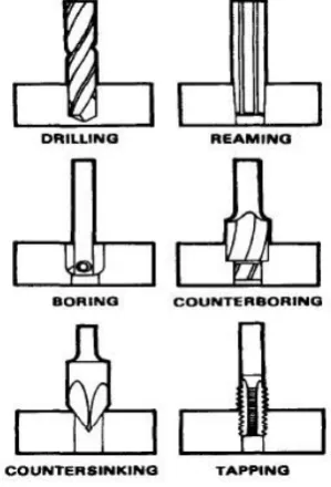
Drilling is a process of producing round holes in a solid material or enlarging existing holes with the use of cutting tools called drills or drill bits. The drill bit is usually a rotary cutting tool, often multi-point cutting tool. The bit is pressed against the work piece and rotated at rates from hundreds to thousands of revolution per minute. Drilling is a continuous machining process. Numerous cutting tools are existed for drilling, but the most mutual is the twist drill. Wide changes of drill processes are accessible to assist different resolves such as drilling, reaming, boring, counter boring, counter sinking and tapping as shown in the Figure-1 below.
A clamp or can be known as fastening device is used to grip an objects securely and tightly to limits the movement through the application of inward pressure. This clamping is very essential during the high speed of the cutting process. The workpiece that are going to be machined must be clamp tightly to get the high precision and accurate results. Generally, clamping provide two main purposes which are hold the workpiece against its locator or prevent movement of the workpiece. However, the main purpose of clamping is to hold the position of the object against the locators firmly throughout the machining cycle. The method can be described as follows:
a) The clamp should allow rapid loading and unloading of parts and be fast-acting.
b) The clamp should not deform the part of damage it.
c) The clamp must have enough strength to restrict its movement and hold the parts.
[image:1.595.92.242.543.763.2]Figure-2. Flow chart.
A. Linear positing table
At the laboratory, there is no jig to clamp the workpiece for the drilling machine.
B. Process
Only covectional machine will be used in the process to optimize this product.
Lathe machine, drilling machine and milling machine are used.
C. Optimization
a) L-Shape plate
First, mild steel plate of 5 mm thickness (Figure-3) is cut by using shear machine as shown in Figure-4 with the dimension of 78 mm x 42 mm.
Figure-3. Mild steel plate.
Figure-4. Shear machine.
Next, 8 mm diameter of the hole is made on that plate surface together with the two holes of 5 mm diameter as shown in Figure-5.
Figure-5. Drilling process.
Figure-6. Welding process.
After that, mild steel plate is undergone the bending process to make it L-shape plate as shown in Figure-6 with the desired dimension. The bending process was done manually with the used of steel hammer (Figure-7) only.
Figure-7. L-shape plate.
Figure-8. Steel hammer.
b) Stopper bar
Aluminum scrap material is used to produce the stopper bar to connect the base rail with the actual table of the drilling machine. That material is cut with the hand saw as shown in Figure-8.
of 10 mm as shown in Figure-9 below. This process is operated by using milling machine.
Figure-10. Squaring process.
Figure-11. Finish squaring process.
Then, continued with the drilling process whereas four holes are drilled with diameter of 8 mm as shown in Figure-11.
Figure-12. Finish drilling process.
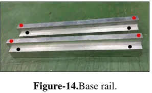
and to prevent the cross shaft from falling down from the base rail. While for the black dot as shown in the Figure-13, it was the holes drilled to connect the base rail with the actual drilling table at the machine (Figure-14).
Figure-14.Base rail.
[image:4.595.95.244.152.243.2]Stopper bar is in the slot of actual table of drilling machine as shown in Figure-14.
Figure-15. Base rail connected with actual table of drilling machine.
The actual location of the stopper is shown in Figure-15 with the used of Allen key socket screw, diameter of 6 mm.
Figure-16. Location of the stopper.
d) Hand Wheel
[image:4.595.84.256.287.381.2] [image:4.595.379.476.305.406.2]As shown in the Figure-16, it is the location for the slot. This slot is made by using the turning machine (Figure-17).
Figure-17. Location of slot.
Figure-18. Turning process.
e) Supporter plate
Connector plate (Figure-18) is the plate that used to connect the cross shaft with the hand wheel. This plate is produced by using the laser cut machine as shown in Figure-18.
Figure-19. Laser cut process.
After that, connector plate is undergone the bending process (Figure-19) by using the CNC hydraulic press brake machine as shown in Figure-20.
[image:4.595.101.237.457.558.2]Figure-20. Bending process.
Figure-21. CNC Hydraulic press brake machine.
[image:4.595.333.486.469.696.2] [image:4.595.101.236.646.734.2]Figure-22. Connector plate in software.
Figure-23. Actual connector plate.
f) Top beam
Two holes are drilled with the diameter of 5 mm at the upper surface of top beam as shown in Figure-23.
Figure-24. Drilled holes.
The holes location for the bearings at the roller housing (sides) is adjusted due to the added part of L-shape plate below its surface.
g) Wood table
Due to the added part of L-shape plate, the screw used to attached wood table with the roller housing (cross shaft) is also need the adjustment in term of its length.
Figure-26. Wooden table from top view.
Figure-27. Before adjusted from behind view.
D. Assembly
a. L-shape plate is connected with the top beam using the screw.
b. Supporter plate is connected with the cross shaft using the screw.
Figure-28. Finish product from the side view.
3. RESULT AND DISCUSSIONS
Table-1. Parameter setup.
Samples
Cutting parameters
Drill bit diameter (mm) Cutting speed (m/min) Feed rate (mm/rev) Depth of cut (mm)
Aluminum 17.5 0.1 2.0 3.5 5.0
Mild Steel 17.5 0.1 1.6 3.5 5.0
Acrylic 17.5 0.1 4.0 - 5.0
Tables 4.13 and 4.14 below shows the result summary for the testing with drill bits diameter of 3.5 mm and 5 mm.
Table-2. For the sample of 3.5 mm.
Not use Use
Aluminum 3.506 3.523
Mild steel 3.505 3.550
Acrylic - -
Table-3. For the sample of 5 mm.
Not use Use
Aluminum 4.997 5.035
Mild steel 4.996 4.989
Acrylic 5.008 4.958
Table-4. Previous result, Aluminum of T=1mm, Drill Bit 3.5mm.
For the aluminum sample, it shows a good result when using the optimized product compared to the result of the previous designed. By using the positioning table for the mild steel and acrylic samples, all of the result obtained also shows a good result. From this testing, it can conclude that product with the optimization design, give the better result of diameter accuracy of the hole compared to the previous design.
During the process to optimize the product, some of the problem is occurred. One of them is the broken of tapping tool. This is happened because of the wrong technic applied during operating it. When using this tool, both hands must be perpendicular with the part that will be tapped, also must apply only the moderate force to that area. Other than that, the use of oil to make it smooth when tapping is suggested. The most important thing is apply the up-and-down method during tapping.
Figure-29. Broken tap.
The next problem is due to the thick thickness of the material, cracked happened to the part. This happened during the bending process took placed. This is the first design of the supporter plate. The design is changed after this problem is occurred by using thin material which is 2 mm.
Figure-30. Cracking part.
Besides, the length of the supporter plate was extra longer whereas it is vibrating more during the movement of the linear drive. The length should be cut by half in order to prevent it from over vibrating and also to reduce the time to move the linear drive to the desired point or location.
Figure-31. Size of supporter plate.
4. CONCLUSIONS
completely optimized followed the process planning as required even it was undergo some modification in term of dimension and process planning in order to increase its efficiency and functionality. The optimization of this linear positioning table even though it was not expressively reduces the process duration to drill the workpiece, it is still can provide high accuracy for the drilling operation.
ACKNOWLEDGEMENT
This work was partially supported by Universiti Teknikal Malaysia Melaka (UTeM) and the Malaysia Ministry of Higher Education for the financial funding under Grant No. FRGS/2018/FTKMP-AMC/F00387.
REFERENCES
[1] Dhanawade A. and Kumar S. 2017. Experimental Study of Delamination and Kerf Geometry of Carbon Epoxy Composite Machined by Abrasive Water Jet. Journal of Composite Materials. p. 2199831668895.
[2] Gadelmawla E.S., Al-Mufadi F. a. and Al-Aboodia. S. 2013. Calculation of the Machining Time of Cutting Tools from Captured Images of Machined Parts Using Image Texture Features. Proceedings of the Institution of Mechanical Engineers, Part B: Journal of Engineering Manufacture. 228(2): 203-214.
[3] Hashim N.L.S., Yahya A., Kadir M.R.A., Samion S. and Mahmud N. 2013. Simulation of Micro-EDM Servomotor for Machining Micro Pits on Hip Implant. Jurnal Teknologi (Sciences and Engineering), 61(2 SUPPL). pp. 45-51.
[4] Kataria R., Kumar J. and Pabla B. 2016. Ultrasonic Machining of WC-Co Composite Material: Experimental Investigation and Optimization Using Statistical Techniques. Proceedings of the Institution of Mechanical Engineers, Part B: Journal of Engineering Manufacture.
[5] Kharagpur I.I.T. 2012. Non-Conventional.