Atomic Scale Simulation of Dislocation Loops Formation
in Thin Foil under High Energy Electron Irradiation
E. Boucetta
Metrology and Information Processing Laboratory University Ibn Zohr, Faculty of
Science ,BP 8106/s Agadir, Morocco
A. M.Gué
Laboratory of Analysis and Architecture of Systems
LAAS-CNRS,7,Av du Colonel Roche 31077 Toulouse Cedex, France
A. Amghar
Metrology and Information Processing Laboratory University Ibn Zohr, Faculty of
Science ,BP 8106/s Agadir, Morocco
D. Estève
Laboratory of Analysis and Architecture of Systems
LAAS-CNRS,7,Av du Colonel Roche 31077 Toulouse Cedex, France
H. Idrissi-Saba
Metrology and Information Processing Laboratory University Ibn Zohr, Faculty of
Science ,BP 8106/s Agadir, Morocco
M.Djafari-Rouhani
Laboratory of Solid State Physics, University Paul Sabatier,118 rte
de Narbonne,31052 Toulouse Cedex. France
ABSTRACT
Using a personnel computer, we have simulated the diffusion and agglomeration of point defects in thin foil under high energy electron irradiation. The physical model has been developed by using the Monte Carlo technique. Four types of reactions are assumed to take place: di-interstitial creation by agglomeration of two free interstitials, vacancy-interstitial annihilation, interstitial trapping by dislocation loops and interstitial annihilation on the sample surfaces. In the simulation only interstitials are mobile and extended defects are assumed to be interstitial type. We have calculated the concentration of point defects, extended defects and the size of the latter. We compared them to the results of the Chemical Reaction Rate Theory (CRRT). It has been found that the dislocation loops are distributed in the center of material leaving areas denuded close to the surface and the loops radius is also strongly dependent on the location of the defect in thin foil with respect to the results of experimental and CRRT. To explain the origin of these phenomena we have exploited the spatial distribution of vacancies close to free surfaces and around dislocation loops. These types of informations are totally missing in the CRRT and experimental.
General Terms
Atomic scale simulation of point defects diffusion
Keywords
Dislocation loops; Atomic Scale Simulation; Diffusion; thin foil; Electronic irradiation.
1. INTRODUCTION
Many experimental and theoretical studies on high energy electron irradiation have been carried out in order to study the growth behaviour of dislocation loop, using respectively the high energy electron microscopy tools [1-17] and the Chemical Reaction Rate Theory (CRRT) [1,4,7,10,18-20]. In the preceding papers [21-22] the present authors have specifically dealt with the atomic scale simulation of the diffusion and agglomeration of point defects under high energy irradiation by using transputer systems of up to 25 processors working in parallel. As a continuation of former
simulations by means of parallel computing, we have developed a sequential software on a personal computer [23-25]. The study has been limited to simulate an infinite lattice and the surface effect is not considered. But in the case of thin foil the surfaces act as effective sinks and it appears absolutely necessary to take their effect into account. In this paper we extended the sequential version to take the real effect of the surfaces into account. After a description of the kinetic rate theory in the section 2, we present the results of the atomic scale simulation that have been performed in simple cubic crystal with a basic cell containing up to N=224 atoms (28 atoms by side). The free boundary conditions are used to simulate thin foil. From the comparison between the theoretical and the simulated results, dislocation loop nucleation behaviour near the surface is made clear by evaluating the surface effect on loop nucleation. Further, the mechanisms which affect the dislocation distribution are examined.
2. ANALYTICAL MODELLING
2.1. Chemical Reaction Rate Theory
The processes of creation of defects in a crystal under high energy electrons irradiation (≥ 1MeV) can be divided into the following stages: the creation of vacancy-interstitial pairs by the incident electron flux, the diffusion of point defects (only interstitials are mobile and the vacancy migration is neglected), the interaction between point defects leads either to the annihilation of interstitials on vacancies or the creation of extended defects and interstitial annihilation on the sample surfaces. Each of these events occurs in a probability depending on the temperature and the activation energy characteristic of the event considered. In this analytical modelling, point defects and extended are supposed to be homogeneously distributed in the crystal. The interaction mechanisms are represented as chemical reactions.The basic reactions can be summarized as follows [1]:
Volume 96– No.10, June 2014
(Vacancy-interstitial annihilation)
(Interstitial agglomeration on loops)
(Interstitial annihilation on the sample surfaces)
(Dissociation of a dislocation
loop)
Variation, versus time, of the defects concentration are thus a balance of creation and annihilation phenomena and the entire processes can be described by resolving the following set of different equations [1]:
Where the symbols i, v, and Snstand respectively interstitials, vacancies and dislocation loops containing (n) interstitials. Ci ,
Cv, and Cb are respectively, interstitials, vacancies and dislocation loops concentration, b is the inter-atomic distance. The rate of point defects creation G is related to the incident flux by . Where σ is the displacement cross section and Ø the electron flux density. Each of these reactions is characterized by a reaction constants Ki expressed by
where Ei is the activation of energy of the corresponding mechanism, k is the Boltzmann constant, T is the temperature (°K) and γ is the atomic vibration frequency.
,where is the migration energy and boundary conditions are: Ci(z=0)=0 and
Ci(z=h)=0 for all t and h is the foil thickness. Due to the symmetry of the system we only considered half of the foil and assume that C(z)=C(h-z).
2.2. Study of Dislocation Loops Formation
Kinetics by CRRT
The results obtained using the CRRRT on CdTe electron have been described in detail in previous papers [1,2] and only the most significant one will be mentioned. The processes of loop nucleation can be divided into two distinct stages (figure 1). At the very beginning only interstitials and vacancies are created and very few dislocation loops are generated. The interstitial density increases very rapidly. When the irradiation time reaches:
(Generally about 10
-4 s)
The dislocation loops begin to nucleate. Then the dominant mechanism becomes the incorporation of interstitials into dislocation loops and the interstitial density decreases slowly. When the interstitial density reaches:
[image:2.595.321.540.87.214.2]The agglomeration probability becomes weaker than the small cluster dissociation probability and no more loops are created.
Fig 1: Interstitial density variation versus time [21]
3. ATOMIC SCALE SIMULATION
3.1. Overview
Unlike the analytical modelling, the atomic scale simulation model is based on an integral three-dimensional treatment of the diffusion of point defects accelerated under irradiation. It treats the defects (point or extended) individually and is able to determine the respective roles of vacancies and interstitials in the dynamic of formation of dislocation loops. The interstitials move in the lattice and during their migration, they react either between themselves, with dislocation loops or with the sample surfaces. These reactions take place in a defined position and affect not the global situation as in the case with the Chemical Kinetics, but the local one. The reactions taken into consideration are the vacancy-interstitial recombination, interstitial-interstitial association to form a nucleus for a new extended defect which is assumed to be interstitial type, annihilation on the sample surfaces and the incorporation of interstitials into already existing dislocation loops leading to their growth. The atomic simulator functions as a result of sequential treatment of the following physical phenomena:
(i) Creation of Frenkel pairs (vacancies-interstitials) (ii) Diffusion of interstitials in the lattice.
(iii) Reaction between defects (Association, Recombination, Growth of dislocation loops and annihilation on the sample surfaces).
The simulator [23-25] is divided into three modules which are executed sequentially:
The first is devoted to the introduction of physical parameters like the total volume of lattice (N=224 atoms, 28 atoms by side), the rate of point defects creation (G) and the irradiation time tfinal.
the minimum distance dmin between various defects is calculated. If this distance is inferior to the action radius of various reactions, the reaction takes place and the point defects coordinates are erased from memory. It has been assumed that the action radius of various reactions is equal to one inter-atomic distance. The use of this number dmin in simulation avoids the examination of the possibilities of reaction after each jump.
The last module is the output module; it provides results in the form of concentration in interstitials, vacancies and dislocation loops, and the mean radius of the latter depending on the irradiation time.
Unlike the chemical kinetics, the coordinates of the point defects and extended, as well as the radius of each dislocation loop, are available during and after irradiation, which allows us to study the space distribution of defects in lattice and to calculate the defects concentrations. Additional details of the simulator used have been presented in Amghar and al [23,24].
The whole architecture of the simulator is the following:
Introduction of physical parameters t=0
While t<tfinal IF t=kT1
Then generation of vacancy-interstitial pair.
Else diffusion Untilt=t+dmin t=t+dmin
- Annihilation on the sample surfaces algorithm - Recombination algorithm
- Association algorithm - Growth algorithm Calculation of the next event
3.2. Simulation Results
3.2.1. Dynamic of Defects Formation
In order to study the influence of the effect of surfaces on diffusion phenomena and formation of dislocation loops during irradiation, we performed many simulations with different parameters (generation time (T1), random series...) in two cases: thin foil and infinite material. The results of interstitials concentration (Ci), vacancies concentration (Cv) and dislocation loops concentration (Cb) and their average radius R have been studied and compared with the results of the chemical reaction rate theory (CRRT) in reduced units [19-25]. In the reduced system, the concentrations are given as ; the time is replaced by a variable without units
and the radius by where G is the generation rate per atom of vacancy–interstitial pairs, K is the temperature dependent hopping rate and the nearest neighbor distance. The advantage of the reduced system is to lead to independent results of experimental conditions (flux and temperature) and to deal with dimensionless quantities.
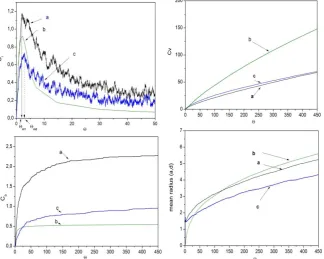
[image:3.595.136.461.399.658.2]The data corresponding to simulations of figure 2 are reported in table 1.
Fig 2: Interstitial concentration Ci, vacancies concentration Cv dislocation loops concentration Cb and average radius R versus
Θ: the chemical reaction rate theory (curves b), atomic scale simulation (a: infinite material, c: thin foil), N=224 and T1=100
The two zones identified in the evolution curve of interstitials
Ci given by the Chemical Reaction Rate Theory (figure1) and Atomic Scale Simulation relative to an infinite lattice which have been the subject of previous works [1,18,21-25] are clearly visible in the simulation curves of a thin foil. The two identified zones are:
(i) The First Zone Θ≤ Θmi (i=1 for the infinite material, i=2
for the thin foil):
Volume 96– No.10, June 2014
surfaces and vacancies, the interstitials number is lower in the case of thin foil (table1). The interstitials concentration reaches its maximum at the end of this zone (Θm1= 1,999 for infinite material and Θm2 =2,863 for thin foil, figure.2). During this interval:
Θ≤ Θm1 ( infinite material): 23,81% of the created interstitials
are recombined with vacancies and 14,56% are used to form new loops while only 2,56% was used for the growth of dislocation loops.
Θ≤ Θm2 (thin foil): Interstitial annihilation on the free surfaces
becomes the dominant mechanism (41,94%) followed by the recombination on the vacancies (27,37%) which causes a decrease in the concentration of interstitials and consequently those of dislocation loops (Only 9 loops against 40 loops in the infinite material). During this phase, where the number of interstitials is maximum and in the presence of the low number of vacancies, the majority of free interstitials are trapped on free surfaces (41,94% at Θ=Θm2). When the number of vacancies in the area close to surface increases, the recombination probability becomes important and therefore the effect of free surfaces, which reaches its maximum at Θm3 (figure 3) decreases over the time.
(ii) The Second Zone Θ> Θmi(i=1 for the infinite material,
i=2 for the thin foil):
The beginning of this zone is marked by an increase in dislocation loops formed in both materials. This decreases considerably the concentration of interstitials.
Θ>Θm1 (infinite material): Due to the number of interstitial
which reaches its maximum, the association rate increases considerably and reaches 23,43%. This rate decreases with the time and reaches 0,11% at Θ= 4391,60. The growth rate is
activated at the same time and passes from 6.42% to 10,37% what proves that the development of the dislocation loops is done into two phases: the association phase where the number of the nucleus increases followed by the growth phase where only the size of the dislocation loops increases. The recombination reaction is the most dominant reaction (89,52% at Θ = 4391,60).
Θ> Θm2 (thin foil): the association reaction is weak in
[image:4.595.320.535.274.415.2]comparison with infinite material (7,07%). After passing through its maximum at Θm3=4, 56 (figure 3), the effect of free surfaces begins to decrease due to the high number of vacancies in the material. This furthers the recombination reaction which starts to dominate during the rest of the irradiation (93,51%). Due to the annihilation of interstitial on the free surfaces and vacancies, the rate of growth reaction remains very weak compared to the other reactions which justifies the decrease of the average radius of the dislocation loops
Fig 3: The evolution of the effect of surfaces versus Θ
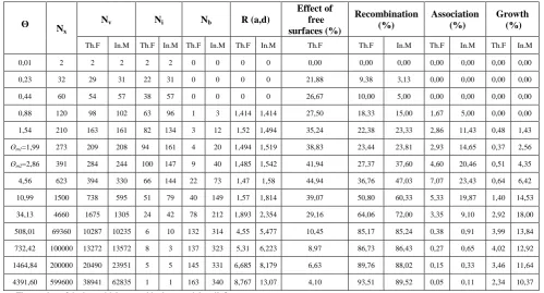
Table 1. The data of the figure 1 obtained for N=224 atoms and T1=100.
ʘ N
x
Nv Ni Nb R (a,d)
Effect of free surfaces (%)
Recombination (%)
Association (%)
Growth (%)
Th.F In.M Th.F In.M Th.F In.M Th.F In.M Th.F Th.F In.M Th.F In.M Th.F In.M
0,01 2 2 2 2 2 0 0 0 0 0,00 0,00 0,00 0,00 0,00 0,00 0,00
0,23 32 29 31 22 31 0 0 0 0 21,88 9,38 3,13 0,00 0,00 0,00 0,00
0,44 60 54 57 38 57 0 0 0 0 26,67 10,00 5,00 0,00 0,00 0,00 0,00
0,88 120 98 102 63 96 1 3 1,414 1,414 27,50 18,33 15,00 1,67 5,00 0,00 0,00
1,54 210 163 161 82 134 3 12 1,52 1,494 35,24 22,38 23,33 2,86 11,43 0,48 1,43
ʘm1=1,99 273 209 208 94 161 4 20 1,494 1,519 38,83 23,44 23,81 2,93 14,65 0,37 2,56
ʘm2=2,86 391 284 244 100 147 9 40 1,485 1,542 41,94 27,37 37,60 4,60 20,46 0,51 4,35
4,56 623 394 330 66 144 22 73 1,47 1,58 44,94 36,76 47,03 7,07 23,43 0,64 6,42
10,99 1500 738 595 51 79 40 149 1,57 1,814 39,07 50,80 60,33 5,33 19,87 1,40 14,53
34,13 4660 1675 1305 24 42 78 212 1,893 2,354 29,16 64,06 72,00 3,35 9,10 2,92 18,00
508,01 69360 10287 10235 6 10 132 314 4,55 5,477 10,45 85,17 85,24 0,38 0,91 3,99 13,84
732,42 100000 13272 13572 8 3 137 323 5,31 6,223 8,97 86,73 86,43 0,27 0,65 4,02 12,92
1464,84 200000 20490 23951 5 5 145 331 6,685 8,179 6,63 89,76 88,02 0,15 0,33 3,46 11,64
4391,60 599600 38941 62835 1 1 163 340 8,767 13,07 4,10 93,51 89,52 0,05 0,11 2,34 10,37
Nx: The number of the interstitials created in the material until Θ.
Nv:The number of the vacancies existing in the material at Θ
Ni: The number of the interstitials existing in the material at Θ
[image:4.595.47.547.458.727.2]Th.F:Thin foil Inf.M: Infinite material
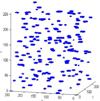
3.2.2. Spatial Distribution of Dislocation Loops
To study the effect of the free surfaces on the distribution of dislocation loops in the thin foil, we carried out many simulations with various values of T1. Figures 4 and 5 show the spatial distribution of dislocation loops for infinite material and thin foil respectively. [image:5.595.325.529.99.447.2]It appears clear from the figures 4 and 6a that the distribution of dislocation loops is homogeneous in an infinite material. However, in the thin foil (figures 5 and 6b) the dislocation loops are distributed in the center of material leaving areas denuded close to the free surfaces. When T1 increases the areas denuded increases and no more loops are created in foil (table 2). This is due to the fact that for high values of T1, the diffusion occurs with long distance and therefore furthers the annihilation of interstitial on the free surfaces. This effect explains why dislocation loops are likely to nucleate from a certain thickness of the thin foil what is in agreement with the experimental results on CdTe [1-3]. Unlike the loops created in the infinite material which are characterized by uniform radius (figure7a), we observe in figure 7b that the free surfaces generate a radius gradient of dislocation loops in the depth of the thin foil. Indeed, the loops radius is strongly dependent on the location of the defect. The Loops created near the free surfaces are characterized by smaller radius compared to those located in the center of the thin foil. This information was also revealed by the experience [4-6] and Chemical Kinetics [4,12,18] but without being able to explain the origin.
Fig 4: Distribution of dislocation loops infinite material (T1=400 ; N=224 atoms)
Fig 5: Distribution of dislocation loops in thin foil (T1=400;N=224 atoms)
Fig 6: calculated loops density versus their location in the foil T1=400 and N=224 atoms [image:5.595.66.271.410.617.2]
Table 2. Simulation results obtained for various values of T1 in two types of material: thin foil and infinite material
T1:
Generation time
Infinite Material Thin Foil Number
of loops
Mean radius
(a. d)
Number of loops
Mean radius (a. d)
200 241 5,857 88 4,336
1000 102 9,087 27 5,565
5000 44 14,026 4 7,915
10000 28 17,654 0 0
20000 15 24,150 0 0
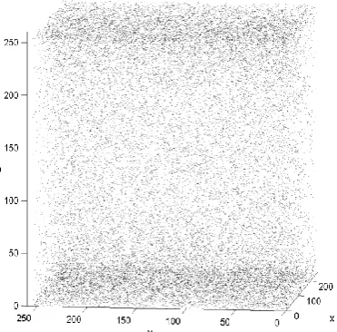
3.2.3. Spatial Distribution of Vacancies
[image:5.595.312.550.544.647.2]Volume 96– No.10, June 2014
both cases (thin foil and infinite material). The concentration of vacancies in thin foil is high close to free surfaces (figure 10b) but in the infinite material (figure10a) the concentration is regular over the volume of the material. Indeed, the free surfaces act like very attractive of the interstitial traps. The interstitials created near the free surfaces annihilate on these latter leaving the vacancies behind them near the edges of the foil. These vacancies, in large numbers, will prevent any possible germination in these areas and the migration of the interstitials to the surfaces is greatly reduced. This explains well the distribution of loops inside the foil (figure 5) and the origin of the gradient of radius observed in figure 7.
Fig 7: calculated mean radius of dislocation loops versus their location in the foil
When the time of irradiation is extended (figure11), the distribution of vacancies changes gradually and their density becomes maximum at the edges of the foil which prevents the migration of the interstitials to the surfaces. That explains the decreases of the effect of the free surfaces observed in figure 3. We also observed the presence of vacancy cloud around the dislocation loops which inhibits the further growth rate of loops as observed in the infinite material [23-25].
Fig 8: Distribution of vacancies in thin after 3.105
vacancy-interstitial pair generations (T1=3500 and N=224)
[image:6.595.59.276.205.395.2]
Fig 9: Distribution of vacancies in infinite material after 3.105 vacancy-interstitial pair generations (T1=3500 and
N=224)
[image:6.595.74.260.501.684.2]Fig 10: calculated vacancies density versus their location in the foils (T1=400 and N=224 atoms).
Fig 11: Distribution of vacancies in thin foil after 3.106 vacancy-interstitial pair generations (T1=3500 and N=2
24
4. CONCLUSION
We have extended our sequential version [23-25] of the atomic scale simulation to take into account the effect of surfaces. The exploitation of the spatial distribution of vacancies allowed us to explain the origin and the mechanisms governing the distribution of dislocation loops over to the volume of thin foil. It is found that the effect of free surfaces generates a modification of the spatial repartition of vacancies in the thin foil. The repartition of vacancies changes gradually during the irradiation and their density becomes high close to free surfaces. This mechanism causes the formation of a layer of vacancies close to free surfaces what prevents the germination of extended defects in these areas in agreement with the experimental results on thin foil CdTe [1-3]. We have found also that the loops radius is strongly dependent on the location of the defect in the foil. The loops formed near the surfaces are their growth diminished compared to those created in the depth of the material. As it is observed in the case of infinite material [23-25], when the time exposure is prolonged, the extended defects are surrounded by a vacancy cloud which reduces their further growth rate.
5. REFERENCES
[1] Gué, A. M., Djafari-Rouhani, M., and Estéve. 1991. Quantitative analysis of defect formation in cadmium telluride during high energy electron irradiation. Rad.Eff & Def.Solids. Radiation Effects and Defects in Solids. 116, 219 .
[2] Gué, A. M., Djafari-Rouhani, M., Estéve, D., and Idrissi-Saba,H.1991. Sur l'origine des inhomogénéités de taille et de concentration des boucles de dislocation créées par irradiation électronique dans le CdTe. J. Phys.I. 1, 97. [3] Gué,A. M., and Mazel, A .1988. Etude expérimentale
de la dynamique de croissance de défauts étendus, sous irradiation électronique à haute énergie, dans le tellurure de cadmium. J. Phys.France. 49, 53
[4] Shimomura, Y,. 1969. Interstitial clusters observed below stage III annealing in electron irradiated pure gold. Philos. Mag. 160, 773
[5] Yoshida, N,. and Kiritani, M. 1973. Point Defect Clusters in Electron-Irradiated Gold. Journal of the Physical Society of Japan . 35, 1418 .
[6] Kiritani, M., Yoshida, N., Takata, H., and Maehara, Y. 1975. Growth of Interstitial Type Dislocation Loops and Vacancy Mobility in Electron Irradiated Metals. J. Phys. Soc. Jpn . 38, 1677 .
[7] Brown, L. M., Kelly, A., and Mayer, R. M. 1969. The influence of boron on the clustering of radiation damage in graphite. Philosophical Magazine. 19, 721.
[8] Fu, C.C., DallaTorre, J., Willaime, F., Bocquet, J. L. and Barbu, A. 2004. Multiscale modelling of defect kinetics in irradiated iron. Nature Materials. 4, 68 .
[9] Bocquet ,J. L. , Doan, N. V,. and Martin, G. 2005. A new formulation of sink strengths under steady irradiation: recombination and interference effects. Phil. Mag. 85, 559.
[10] Brown,L. M. 1969. On electron radiation damage in crystals. Philos. Mag .19, 869 .
[11]Zinkle, S .J. 2012. Effect of H and He irradiation on cavity formation and blistering in ceramics. Revue Phys. Appl . 15, 307.
[12]Legros de Mauduit B, Alcouffe G and Reynaud F 1980 Irradiation électronique de l'antimoine: Montee des dislocations mixtes et determination de la nature des boucles de defauts ponctuels. Radiation Effects.53,55-56.
[13]Shigenaka, N., Hashimoto, T., and Fuse, M. 1994. Effect of specimen surface on dislocation loop nucleation under ion irradiation. Materials Transactions, JIM(Japan).35, 7. [14] Xu ,W., Zhang, Y., Cheng, G., Jian, W., Millett, P. C. ,
Koch ,C. C. , Mathaudhu ,S . N., and Zhu, Y. 2013. In-situ atomic-scale observation of irradiation-induced void formation. Nature communications. 4.
[15]Yoshiie, T.,Kojima,S,. and kiritani, M. 1994. Nucleation of Interstitial Type Dislocation Loops in Metals under Neutron Irradiation. Sci.Rep.RITU. 40, 77.
[16]Yang, Z., Sakaguchi, N., Watanabe, S,. and Kawai, M,. 2011. Dislocation Loop Formation and Growth under In Situ Laser and/or Electron Irradiation. Scientific Reports 1, 190.
[17] Urban, K. 1971. Growth of defect clusters in thin nickel foils during electron irradiation (I). physica status solidi (a). 4, 761
[18] Bourret, A. 1970. L'agglomeration des defauts ponctuels dans les metaux irradies decrite par les equations de la cinetique chimique. Radiation Effects. 5, 27.
[19]Dienes ,G. J., and Vineyard, G. H . 1957. Rad. Effects . 2, 226 .
[20]Damaskn,A. C,. and Dienes, G. J. 1963. Point Defects in Metals, Gordon and Breach, New York and London Chap. II
[21] Djafari-Rouhani, M., Idrissi-Saba, H., and Gué,A. M. 1998. A tomic Scale Simulation of Point Defects Diffusion and Reactions Using Transputers. Jpn.J.Appl.Phys. 37, 2703.
[22] Djafari-Rouhani, M., Gué,A.M., Idrissi-Saba,H., and Estéve, D. 1994. Simulation à l'échelle atomique de la formation des boucles de dislocation sous irradiation. J. Phys.I France. 4, 453.
[23]Amghar, A., Djafari-Rouhani, M., Idrissi-Saba,H., Gué,A.M, and Estéve, D. 2001. Simulation à l'Échelle
atomique des Phénomènes de Diffusion et
d'Agglomération des défauts Ponctuels Sous Irradiation: Création et Croissance des Boucles de Dislocation. Physica B. 304, 368.
[24]Amghar, A., Idrissi-Saba, H., Saba, A., Djafari-Rouhani, M., Gué, A.M, and Estève, D. 2001. Atomic scale simulation of extended defects formation under high energy electron irradiation: space distributionn. Physica. Scripta. 64, 75.
![Fig 1: Interstitial density variation versus time [21]](https://thumb-us.123doks.com/thumbv2/123dok_us/8041156.771446/2.595.321.540.87.214/fig-interstitial-density-variation-versus-time.webp)