Design and Analysis of Connecting Rod for
Different Material Using Ansys Workbench 16.2
Vikas Singh1, Sumit Kr. Verma2, Harish Chandra Ray3, Vishal Kr. Bharti4, Abhinesh Bhaskar5 Department of Mechanical, Rajkiya Engineering College, Banda, Uttar Pradesh, India-210001
Abstract: connecting rods are practically generally used in all varieties of automobile engines. Connecting rod acting as a converting intermediate link between the piston and the crankshaft of the engine, by the reciprocating motion of the piston to the rotary motion of crankshaft. Thus, this study aims to carry out for the load strain, stress, total deformation and analysis of factor of safety of pin end of the connecting rod of different materials. Generally connecting rods are manufactured using carbon steel and in recent days aluminium alloys are used for manufactured the connecting rods. In this work existing connecting rod material are replaced by beryllium alloy and magnesium alloy. Fea analysis was carried out by considering five material aluminium 360, forged steel, titanium alloy, ti-13v-11cr-3al, magnesium alloy, beryllium(alloy 25). In this study a solid 3d model of connecting rod was developed using solid works-2016 software and analysis was carried out by ansys 16.2 software and useful factors like stress, strain etc. Were obtained. Our main objective to determine best material for connecting rod after analysing at ansys workbench 16.2.
I. INTRODUCTION
Internal Combustion engine has many parts like cylinder, piston, connecting rod, crank and crank shaft. The connecting rod is very important part of an engine. Working of the connecting rod is to transmit power of piston to crank pin. Connecting rod has two ends one is pin end and other is crank end. Pin end is attached with piston. The big end (crank end) is attached to the crank pin by a crank shaft. The function of crank shaft is to transmit the reciprocating motion of piston into rotary motion. The connecting rod should be such that it can sustain the maximum load without any failure during high cycle fatigue. The connecting rod has generally three parts pin end, crank end, and long shank. Design of shank can be different type like rectangular, tubular, circular, I-section and H-section. Circular section is generally used for low speed engines. I-section is used for high speed engines.
Fig-1 Schematic diagram of connecting rod
A. Kuldeep B “Analysis and optimization of connecting rod using ALFASiC composites”. Generally connecting rods are
describes the modelling and analysis of connecting rod. FEA analysis was carried out by considering two materials. The parameter like von misses stress, von misses strain and displacements were obtained from ANSYS software. Compared to the former material the new material found to have less weight and better stiffness. It resulted in reduction of 43.48% of weight, with 75% reduction in displacement. [1]
B. Prof. N.p.doshi “analysis of connecting rod using analytical and finite element method”. The most common types of materials
used for connecting rods are steel and aluminium. Connecting rods are widely used in variety of engines such as, in-line engines, v-engine, opposed cylinder engines, radial engines and oppose-piston engines. For the project work we have selected connecting rod used in light commercial vehicle of tata motors had recently been launched in the market. We found out the stresses developed in connecting rod under static loading with different loading conditions of compression and tension at crank end and pin end of connecting rod. Design of connecting rod which is designed by machine design approach is compared with actual production drawing of connecting rod. We found that there is possibility of further reduction in mass of connecting rod. [2]
C. Webster et al. (1983) performed three dimensional finite element analysis of a high-speed diesel engine connecting rod. For this
analysis they used the maximum compressive load which was measured experimentally, and the maximum tensile load which is essentially the inertia load of the piston assembly mass. The load distributions on the piston pin end and crank end were determined experimentally. They modelled the connecting rod cap separately, and also modelled the bolt pretension using beam elements and multi point constraint equations. [3]
D. Yoo et al. (1984) used vibrational equations of elasticity, material derivative idea of continuum mechanics and an ad joint variable technique to calculate shape design sensitivities of stress. The results were used in an iterative optimization algorithm, steepest descent algorithm, to numerically solve an optimal design problem. The focus was on shape design sensitivity analysis with application to the example of a connecting rod. The stress constraints were imposed on principal stresses of inertia and firing loads. But fatigue strength was not addressed. The other constraint was the one on thickness to bound it away from zero. They could obtain 20% weight reduction in the neck region of the connecting rod. [4]
E. Folgar et al. (1987) developed a fibre fp/metal matrix composite connecting rod with the aid of fea, and loads obtained from kinematic analysis. Fatigue was not addressed at the design stage. However, prototypes were fatigue tested. The investigators identified design loads in terms of maximum engine speed, and loads at the crank and piston pin ends. They performed static tests in which the crank end and the piston pin end failed at different loads. Clearly, the two ends were designed to withstand different loads. [5]
F. Serag et al. (1989) developed approximate mathematical formulae to define connecting rod weight and cost as objective functions and also the constraints. The optimization was achieved using a geometric programming technique. Constraints were imposed on the compression stress, the bearing pressure at the crank and the piston pin ends. [6]
G. Sarihan and song (1990), for the optimization of the wrist pin end, used a fatigue load cycle consisting of compressive gas load
corresponding to maximum torque and tensile load corresponding to maximum inertia load. Evidently, they used the maximum loads in the whole operating range of the engine. To design for fatigue, modified goodman equation with alternating octahedral shear stress and mean octahedral shear stress was used. [7]
H. Balasubramaniam et al. (1991) reported computational strategy used in mercedes- benz using examples of engine components.
In their opinion, 2d fe models can be used to obtain rapid trend statements, and 3d fe models for more accurate investigation. The various individual loads acting on the connecting rod were used for performing simulation and actual stress distribution was obtained by superposition. The loads included inertia load, firing load, the press fit of the bearing shell, and the bolt forces. No discussions on the optimization or fatigue, in particular, were presented. [8]
I. athavale and sajanpawar (1991) modelled the inertia load in their finite element model. An interface software was developed to
apply the acceleration load to elements on the connecting rod depending upon their location, since acceleration varies in magnitude and direction with location on the connecting rod. They fixed the ends of the connecting rod, to determine the deflection and stresses. This, however, may not be representative of the pin joints that exist in the connecting rod. The results of the detailed analysis were not discussed, rather, only the modelling technique was discussed. The connecting rod was separately analysed for the tensile load due to the piston assembly mass (piston inertia), and for the compressive load due to the gas pressure. The effect of inertia load due to the connecting rod, mentioned above, was analysed separately. [9]
J. Hippoliti (1993) reported design methodology in use at piaggio for connecting rod design, which incorporates an optimization
Two parametric FE procedures using 2D plane stress and 3D approach developed by the author were compared with experimental results and shown to have good agreements. [10]
K. sonsino and esper (1994) have discussed the fatigue design of sintered connecting rods. they did not perform optimization of the
connecting rod. they designed a connecting rod with a load amplitude fa = 19.2 kn and with different regions being designed for different load ratios (r), such as, in the stem fm = -2.2 kn and r = -1.26, at the piston pin end fm = -5.5 kn and r = -1.82, at the crank end fm = 7.8 kn and r = -0.42. they performed preliminary fea followed by production of a prototype. fatigue tests and experimental stress analysis were performed on this prototype based on the results of which they proposed a final shape, shown in figure 1.4. in order to verify that the design was sufficient for fatigue, they computed the allowable stress amplitude at critical locations, taking the r-ratio, the stress concentration, and statistical safety factors into account, and ensured that maximum stress amplitudes were below the allowable stress amplitude. [11]
L. ishida et al. (1995) measured the stress variation at the column centre and column bottom of the connecting rod, as well as the
bending stress at the column centre. the plots, shown in figures 1.5 and 1.6 indicate that at the higher engine speeds, the peak tensile stress does not occur at 360o crank angle or top dead centre. it was also observed that the r ratio varies with location, and at a given location it also varies with the engine speed. the maximum bending stress magnitude over the entire cycle (0° to 720° crank angle) at 12000 rev/min, at the column centre was found to be about 25% of the peak tensile stress over the same cycle. [12]
M. rabb (1996) performed a detailed fea of the connecting rod. he modelled the threads of the connecting rod, the threads of connecting rod screws, the prestress in the screws, the diametral interference between the bearing sleeve and the crank end of the connecting rod, the diametral clearance between the crank and the crank bearing, the inertia load acting on the connecting rod, and the combustion pressure. the analysis clearly indicated the failure location at the thread root of the connecting rod, caused by improper screw thread profile. the connecting rod failed at the location indicated by the fea. an axisymmetric model was initially used to obtain the stress concentration factors at the thread root. these were used to obtain nominal mean and alternating stresses in the screw. a detailed fea including all the factors mentioned above was performed by also including a plasticity model and strain hardening. based on the comparison of the mean stress and stress amplitude at the threads obtained from this analysis with the endurance limits obtained from specimen fatigue tests, the adequacy of a new design was checked. load cycling was also used in inelastic fea to obtain steady state situation. [13]
N. pai (1996) presented an approach to optimize shape of connecting rod subjected to a load cycle, consisting of the inertia load
deducted from gas load as one extreme and peak inertia load exerted by the piston assembly mass as the other extreme, with fatigue life constraint. fatigue life defined as the sum of the crack initiation and crack growth lives, was obtained using fracture mechanics principles. the approach used finite element routine to first calculate the displacements and stresses in the rod; these were then used in a separate routine to calculate the total life. the stresses and the life were used in an optimization routine to evaluate the objective function and constraints. the new search direction was determined using finite difference approximation with design sensitivity analysis. the author was able to reduce the weight by 28%, when compared with the original component. [14]
as we seen in above references forged steel was use primarily but due to its heavy weight speed of engine reduced then after aluminium alloy was used so that speed of the engine increases but there large variation in stress and deformation in compared to other materials that were searched in that time like magnesium alloy, titanium alloy, as comparison with those materials beryllium 25 is the better among them because there is small variation in stress, strain, and total deformation.
Fig-2(a) Fig-2(b) Fig-2(c) Fig-2(d)
O. Forces acting on the connecting rod
Fig-3 Vertical representation of connecting rod
P. Pressure Calculation for Connecting Rod
Engine type 4-stroke air cooled Bore X Stroke = 57 × 58.6 mm Displacement = 149.5 cc
Maximum Power = 13.8bhp@8500rpm Compression Ratio = 9.35: 1
Density of petrol (C8H18) = 737.22kg/m3=737.22E-9 kg/mm3
Auto ignition temp. = 280°c (536°F) = 553°k Mass= Density×Volume
= 737.22e-9x149.5e = 0.110214kg
Molecular weight of petrol = 114.228g/mole = 0.11423 kg/mole Where, P = Pressure, MPa
V = Volume m = Mass, kg
Rspecific = Specific gas constant T = Temperature,°k
Rspecific = R/M
Rspecific = 8.3143/0.114228 Rspecific = 72.76 Nm/kg K P = m.Rspecific.T/V
P = (0.110214 x 72.757 x 553) / 149.5 = 29.67 MPa
Calculation of analysis is done for maximum Pressure of 30 MPA and 15 MPA.
Q. Design Calculation For The Connecting Rod In general From standards, 1) Thickness of the flange & web of the section = t
2) Width of the section, B = 4t
3) Height of the section, H = 5t
4) Area of the section, A = 11t2\
6) Moment of inertia about y-axis Iyy= 10.91t
7) Therefore Ixx / Iyy = 3.2 (safe because it lies between 3 to 3.5)
8) Length of the connecting rod (L) = 2 times stroke L = 117.2 mm
Total Force acting F = FP-FI
Where Fp = force acting on the piston FI= force of inertia
FP = ( d2) x gas pressure
FP = 39473.1543 N
FI = mw2r(cosθ± )
m = mass of the reciprocating parts Weight = 1.6 * 9.81 = 15.696 N r = crank radius
r = stroke of piston / 2 r = 58.6/2 = 29.3mm
Also, ɵ = Crank angle from dead centre
ɵ= 0 considering connecting rod is at TDC position n = length of connecting rod / crank radius
g = acceleration due to gravity, 9.81m s⁄ 2 v = crank velocity m/s
w = 2πn 60⁄ w = 2π8500/60 = 890.1179 v = r w = 29.3e-3×890.1179 = 26.08 m/sec On substituting these,
FI = 9285.5481 Thus,
F = 39473.1543 – 9285.5481 F = 30187.6062 N Now, According to Rankine’s – Gordon formula,
F =
( )
Let,
A = Cross-section area of connecting rod, L = Length of the connecting rod FC = Compressive yield stress, F = Buckling load
Ixx & Iyy = Radius of gyration of section about the x
– x and y – y axis resp. Kxx & Kyy = Radius of gyration of section about x – x and y – y axis resp. For Magnesium Alloy:
Fc=160Mpa
30187.6 = ×
. ( . .)
t = 4.08mm
Width B = 4t = 4x4.08 =16.32mm Height H = 5t = 20.40mm
At the small end (H1) =.85H=.85x20.40=17.34mm
At the big end (H2) = 1.2H=1.2x20.40=24.48mm
R. Design of small end
39473.154 = 1.5 10
dp = 51.29mm
lp = 76.5mm
Outer diameter of small end=dp+2tb+2tm
=51.29 + (2 x 2) + (2 x 5)
=65.29mm
Design of big end:
= = 1.25 7.5
39473.154 = 1.25 7.5
= 64.88
II. ANALYSIS OF CONNECTING ROD
The connecting rods are most usually made of steel for production engines, but can be made of aluminium (for lightness and the ability to absorb high impact at the expense of durability) or titanium (for a combination of strength and lightness at the expense of affordability) for high performance engines, or of cast iron for applications such as motor scooters.
A. Problem Formulation
The objective of the present study is to design and analysis of two wheeler connecting rod and to find the best alternative material of connecting rod. In the present study beryllium alloys and magnesium alloys have taken in place of currently using materials like aluminium 360 for CAE analysis and a meaningful comparison made among AL360, Beryllium alloy and Magnesium alloy for choosing the alternative of existing material using for manufacture the connecting rod of single cylinder 4 stroke combustion engines. In this work, an analysis is done for aluminium alloy, magnesium alloy and beryllium alloy. Beryllium alloys feature high fatigue strength and resistance to wear, corrosion, galling, and stress relaxation.
B. Properties of Materials
Aluminium 360 Table-2.1 Composition
Aluminium Bal.
Copper .6
Magnesium 0.4-0.6
Iron 13
Lead ---
Tin 0.15
Nickel 0.50
Zinc 0.50
Manganese 0.35
Table2.2 Physical Properties
Material Alloy Density Melting
Pt(C)
Thermal Conductivity(w/mK)
Coefficient of Thermal Expansion(µm/mK)
Electrical Conductivity
Aluminium Al
360
2.63 577 113 21 29
Table 2.3Mechanical Properties
Material Alloy Tensile
Strength
Yield Strength
Shear Strength
Hardness Elongation
Mpa Mpa Mpa Brinell(HB) %in 50 mm
Aluminium Al 360 317 170 180 75 35
Magnesium Alloy
Table 2.4 Composition
Aluminium 8.3-9.7
Copper 0.03
Magnesium Bal.
Iron 0.005
Nickel 0.002
Zinc 0.35-1.0
Manganese 0.15-0.5
Silicon 0.1
Other-Metallic 0.02
Table 2.5 Physical Properties
Material Alloy Density Melting
Point
Thermal Conductivity
Coefficient
of thermal
Expansion
Electrical Conductivity
g/cm^3 C W/mK µm/mK %IACS
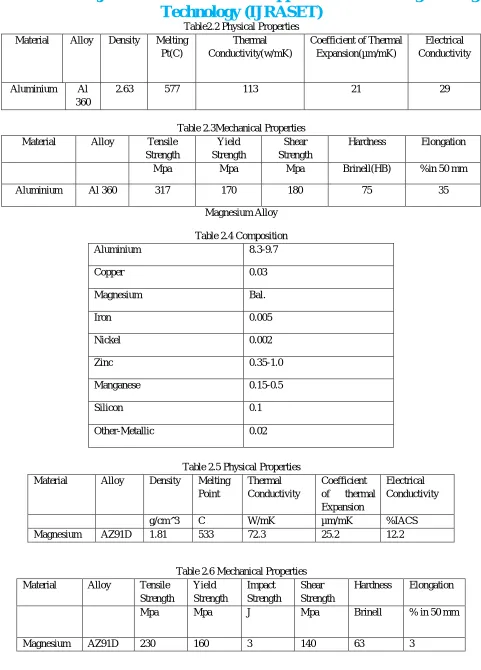
[image:9.612.65.546.56.726.2]Magnesium AZ91D 1.81 533 72.3 25.2 12.2
Table 2.6 Mechanical Properties
Material Alloy Tensile
Strength Yield Strength Impact Strength Shear Strength
Hardness Elongation
Mpa Mpa J Mpa Brinell % in 50 mm
Beryllium 25
Table 2.7 Composition
Weight % Min. Max.
Be 1.80 2.00
Co+Ni 0.20 0.50
Fe 0.10
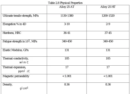
[image:10.612.83.528.218.543.2]Cu Balance
Table 2.8 Physical Properties
Alloy 25 AT Alloy 25 HT
Ultimate tensile strength, MPa 1130-1380 1200-1520
Elongation % in 4D 3-10 2-9
Hardness, HRC 36-41 37-45
Fatigue strength in 10 , MPa 340-450 340-450
Elastic Modulus, GPa 131 131
Thermal conductivity,
w m⁄ .C
105 105
Thermal expansion,
ppm ⁄ ′C
17 17
Magnetic permeability < 1.001 < 1.001
Density,
g cm⁄
[image:10.612.95.520.580.688.2]8.36 8.36
Table 2.9 Mechanical Properties
Ultimate Tensile Strength 1280-1480 Mpa
Yield Strength 965-120 Mpa
Young Modulus 125-130 Gpa
Poisson’s ratio 0.33
Modulus of rigidity 50 Gpa
Table 2.10 Composition
Vanadium 12.5-14.5
Chromium 10-12
Aluminium 2.5-3.5
Iron 0.35
Oxygen 0.17
Carbon 0.05
Nitrogen 0.05
[image:11.612.146.467.86.280.2]Titanium Remainder
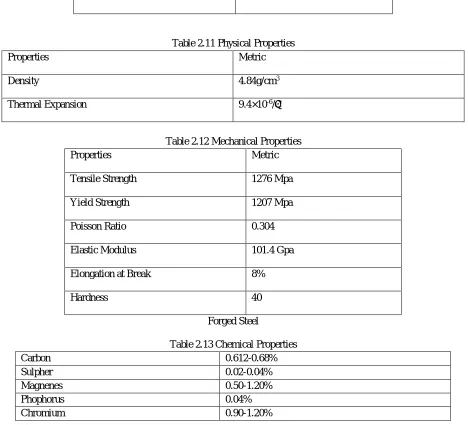
Table 2.11 Physical Properties
Properties Metric
Density 4.84g/cm3
Thermal Expansion 9.4×10⁻⁶/֠C
Table 2.12 Mechanical Properties
Properties Metric
Tensile Strength 1276 Mpa
Yield Strength 1207 Mpa
Poisson Ratio 0.304
Elastic Modulus 101.4 Gpa
Elongation at Break 8%
Hardness 40
Forged Steel
Table 2.13 Chemical Properties
Carbon 0.612-0.68%
Sulpher 0.02-0.04%
Magnenes 0.50-1.20%
Phophorus 0.04%
[image:11.612.73.541.266.691.2]Table 2.14 Mechanical Properties
Density(g/cc) 7.7
Average Hardness(HRB) 101
Yield Strength(Mpa) 625
Ultimate Strength(Mpa) 625
Percent Reduction in Area 58
Modulus of Elasticity(Gpa) 221
Poission Ratio 0.21
C. Comparison of Materials
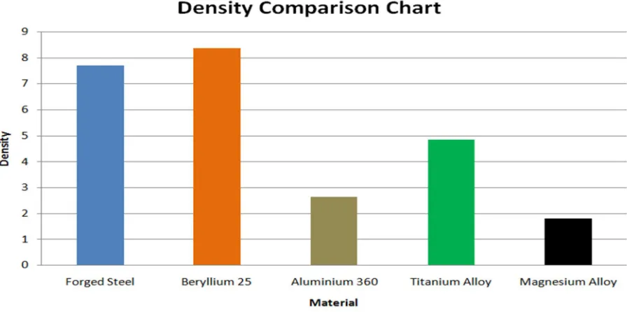
[image:12.612.83.531.415.638.2]1) Density Comparison: The connecting rod has a tremendous field of research. In addition to this, vehicle construction led the invention and implementation of quite new materials which are light and meet design requirements. And the optimization of connecting rod had already started as early year 1983 by Webster and his team. There are many materials which can be used in connecting rod for optimization. In modern automotive internal combustion engines, the connecting rods are most usually made of steel for production engines, but can be made of aluminium (for reducing the weight and the ability of absorbing high impact at the expense of durability) or titanium (for a high performance engines) or of cast iron for applications such as motor scooters. In this study materials compared are Forged Steel, Beryllium 25, Aluminium 360, Titanium alloy, Magnesium alloy. In this comparison we replace Beryllium alloy by Titanium alloy.
Fig-4 Density comparison chart
results obtained from the analysis, it is concluded that the stress induced in the beryllium alloy is less than the aluminium and magnesium alloy.
Fig-5 Weight comparison chart
3) Young Modulus
Here we compared Young’s Modulus of five different materials. Materials are Aluminium 360, Forged Steel, Beryllium 25, Titanium Alloy and Magnesium Alloy.
Fig-6 Young modulus chart
III. ANALYSIS ON ANSYS WORKBENCH 16.2
A. Introduction to Ansys
Fig-7 Static Structural Analysis System
1) Create Analysis System
a) Take one of the readymade stencil from the tool box according to the need of the project.
b) In this project we took static structural as analysis system for the analysis of connecting rod.
To analysing connecting rod using different material at Ansys workbench 16.2 following step have been followed:-
Fig-8 First view of static structure
2) Define Engineering Data
a) In this section material for the current project is assigned
b) In ansys by default structural steel is selected
c) To assign new material turn on the engineering data source
d) Generate new library for connecting rod
e) Make a tick mark on the new generated library named connecting rod to convert it into edit mode.
f) Add different four material which is kept under study as shown in figure-9 below
g) After giving all required properties for connecting rod save them into the Library
i) Add all the four materials in the content by clicking on the plus sign as shown below-
Fig-9 Adding new material
3) Importing External Geometry: As design of connecting rod is done on SOLID WORKS is imported as shown below:-
Fig-10 Importing external geometry
4) Meshing After importing the external geometry further function is meshing. Meshing is done for better accuracy in result. It is many
types-a) Triangular meshing
b) Rectangular meshing
Fig-11 Generate meshing
5) Working on Model
a) After meshing we go to SET UP we click on CONNECTING and see like this-
Fig-12 Giving new material to connecting rod
b) In Details of CONNECTING click on assignment we see there are importing materials.
c) Then we selecting one of them for further implementation.
Fig-13 Giving fixed support
7) Definition of Stress: To define stress various theories have been already assigned in the ansys like Von-Mises, Maximum principal etc. In this project Von- Mises used as stress theory.
Fig-14 Applied stress in model
8) Deformation: Two type of deformation is given in
ansys-a) Total Deformation It is the volumetric deformation in geometry.
Fig-15 Total deformation in connecting rod
9) Strain: There are many type of strain in ansys as von-mises, maximum principle strain, maximum shear strain. In this project we discuss only von-mises strain.
Fig-16 Strain in model
Fig-17 Stress comparison chart
2) Strain Comparison
Fig-18 Strain comparison chart
3) Deformation Comparison
IV. RESULTS AND DISCUSSION A. Analysis of Connecting Rod of Forged Steel
Fig-20 Equivalent Stress Analysis
Fig-22 Equivalent Deformation Analysis
Table-4.1 Result and Analysis
Minimum Maximum
Stress 1.4876x10⁶ 3.0518x10⁸
Strain 8.7461x10⁻⁶ 0 .0015389
Deformation 0.0 0.00011242
B. Analysis of Connecting Rod of Aluminium 360-
Fig-24 Equivalent Strain Analysis
Fig-25 Equivalent Deformation Analysis
Table-4.2 Result and Analysis
Minimum Maximum
Stress 1.334x10⁶ 2.9557x10⁸
Strain 1.9632x10⁻⁵ 0 .0044616
C. Analysis of Connecting Rod of Magnesium Alloy
Fig-26 Equivalent Stress Analysis
Fig-27 Equivalent Strain Analysis
Table-4.3 Result and Analysis
Minimum Maximum
Stress 1.5246x10⁶ 2.9968x10⁸
Strain 3.7544x10⁻⁵ 0 .0076026
Deformation 0.0 0.00056179
D. Analysis of Connecting Rod of Beryllium 25-
Fig-29 Equivalent Stress Analysis
Fig-31 Equivalent Deformation Analysis
Table-4.4 Result and Analysis
Minimum Maximum
Stress 1.334x10⁶ 2.95578x10⁸
Strain 1.1151x10⁻⁵ 0.0025342
Deformation 0.0 0.00018849
E. Analysis of Connecting Rod of Ti-13V-11Cr-3Al.
Fig-33 Equivalent Strain Analysis
Fig-34 Equivalent Deformation Analysis
Table-4.5 Result and Analysis
Minimum Maximum
Stress 1.4385x10⁶ 2.9774x10⁸
Strain 1.2413x10⁻⁵ 0.002651
V. CONCLUSION
A. Solid modelling of connecting rod was made in fusion 360 according to production drawing specification and analysis under the
effect of tensile and compressive loads in terms of pressure is done in ANSYS Workbench.
B. From analysis it is observed that the minimum stresses among all loading conditions, were found at crank end cap as well as at
piston end. So the material can be reduced from those portions, thereby reducing material cost. For further optimization of material dynamic analysis of connecting rod is needed. After considering dynamic load conditions once again finite element analysis will have to be performed. It will give more accurate results than existing.
C. It is the conclusion of this study that the connecting rod can be designed and optimized under a load range comprising compressive load as one extreme load and tensile load. Furthermore, the existing connecting rod can be replaced by optimization with a new connecting rod made of lighter in weight (approx. 15%).
D. From the above analysis we can conclude that stresses of all the materials are almost comparable and also in safe limit, i.e., well
below the yield stress.
E. The section modulus of the connecting rod should be high enough to prevent high bending stresses due to inertia forces.
F. Weight of connecting rod is reduced, Thereby reduces the inertia force by comparing the results of three different materials used for connecting rod analysis it is found that equivalent von mises stress for all the materials is approximately same.
G. From the static analysis the stress is found maximum at the small end of the connecting rod.
H. Carbon steel as a connecting rod material is less stiff and having more weight than forged steel and other material taking in consideration.
I. Forged steel connecting rod is having more weight than Aluminium, magnesium and beryllium alloys connecting rod.
J. Aluminium alloy connecting rod is having more weight and displacement than magnesium and beryllium alloys. So,
aluminium connecting rod show more shaky behaviour.
K. Maximum von mises stress, Maximum von mises strain and Maximum displacement are minimum in connecting rod of
Beryllium alloy.
L. Comparing the different data it is observed that stress, strain and displacement is minimum in beryllium alloy connecting rod.
So, beryllium alloy can be used for production of connecting rod for longer life.
VI. FUTURE SCOPE
A. Vibrational analysis can be done at ansys for minimizing the premature failure.
B. Dynamic analysis of connecting rod can also be performed on ansys to get the better analysis.
C. Thermal analysis can be done of connecting rod to minimize the thermal stress effect on connecting rod.
D. Torsional analysis can be done due to presence of small amount of torsional moment at the end points.
E. Design modification can be done to minimize the weight of connecting rod and the inertia force.
F. Work on the internal coating of hard material inside the both ends can be done to minimize the wear failure in connecting rod.
REFERENCES
[1] Kuldeep B, Arun L.R, Mohammed Faheem “ANALYSIS AND OPTIMIZATION OF CONNECTING ROD USING ALFASiC COMPOSITES”, ISSN:
2319-875, International Journal of Innovative Research in Science, Engineering and Technology, Vol. 2, Issue 6, June 2013
[2] Prof. N.P.Doshi, 1 Prof .N.K.Ingole “ANALYSIS OF CONNECTING ROD USING ANALYTICAL AND FINITE ELEMENT METHOD”
INTERNATIONAL JOURNAL OF MODERN ENGINEERING RESEARCH” (IJMER) www.ijmer.com Vol.3, Issue.1, Jan-Feb. 2013, ISSN: 2249-6645.
[3] Webster.w.d, coffell R, and Alfaro D. “Modelling and analysis of two wheelr connecting rod while using ansys software” IOSR Journal mechanical and civil
engineering.
[4] Yoo et al., M.M. Rahman, M.M. Noor, K. Kadirgama and A.K. Amirruddin “DESIGN OF CONNECTING ROD OF INTERNAL COMBUSTION ENGINE:
ATOPOLOGY OPTIMIZATION APPROACHM” National Conference in Mechanical Engineering Research and Postgraduate Studies (2nd NCMER 2010)3-4 December 2010, pp.155166
[5] FOLGAR Analysis of Connecting Rod Using Analytical and Finite Element‟ International Journal of Modern Engineering Research (IJMER), JanFeb. 2013,
Vol.3, Issue.1, pp-65-68
[6] SERAJ, Mohammad Reza Asadi, Masoud Mohammadi, Ahangari Heidar., 2011, Fatigue Analysis of Connecting Rod of Samand Engine by Finite Element
Method, Australian Journal of Basic and Applied Sciences, ISSN 1991-8178, 5(11): 841-845.
[7] SARIHAN and SONG, Design Evaluation and Optimization of Connecting Rod Parameters Using FEM International Journal of Engineering and Management
Research, Vol.-2, Issue-6, December 2012.
[8] BALASUBRAMANIAM.Vijaya Bhaskar Reddy, Modeling and Analysis of Two Wheeler Connecting Rod by Using Ansys, IOSR Journal of Mechanical and
[9] ATHAVALE and SAJANPAWER, Yongqi Liu and Ruixiang Liu, Stress and Fatigue of Connecting Rod in Light Vehicle Engine, The Open Mechanical Engineering Journal, pp- 14-17, 2013.
[10] HIPPOLITY, Analysis of Connecting Rod Using Analytical and Finite Element Method, International Journal of Modern Engineering Research (IJMER),
Vol.3, Issue.1, Jan-Feb. 2013 pp-65-68.
[11] SONSINO and ESPER, Stress Analysis of I.C. Engine Connecting Rod by FEM, International Journal of Engineering and Innovative Technology (IJEIT)
Volume 1, Issue 3, March 2012
[12] ISHIDA“STRUCTURAL ANALYSIS OF BUSH BEARING FOR SMALL END CONNECTING ROD USING “PROMECHANICA” ISSN 0975 – 668X|
NOV 12 TO OCT 13 | VOLUME – 02. 2344-02
[13] RABB“FINITE ELEMENT ANALYSIS OF CONNECTING ROD USING ANSYS” Proceedings of Third IRF International Conference on 8th February
2015, Cochin, India, ISBN: 978-93-84209-88-9.