Technology (IJRASET)
Low Cost Reliable 3D Printer Design Using
CPU Board XMC4500
S. Suresh1 (PG Scholar), V.Senthilkumaran 2 (Assistant Professor)
Department of Electronics & Communication Engineering, Mahendra Engineering College, Namakkal District, TN, India.
Abstract--3D printing is a process of making a three-dimensional solid object of virtually any shape from a digital model. A 3D printer is just like a normal color printer. The main difference is that it prints with plastic and 3-imensional objects. The printer prints small plastic threads in layers forming the object as required. 3D printing is achieved using an additive process where successive layers of material are laid down in different shapes. So, in this I have used five stepper motor and one extruder from which layer by layer object forming by serial communication with pc and communicate 3D printer by using CAD software to receive 3D object with help of controllerXMC4500.
Keywords: xmc4500, G-Code, Marlin Software, Printed Head (EXTRUDER), ABS Plastic, Power Supply.
I. INTRODUCTION
3D printing is a form of additive manufacturing technology where a three dimensional object is created by laying down successive layers of material. It is also known as rapid prototyping, is a mechanized method whereby 3D objects are quickly made on a reasonably sized machine connected to a computer. A 3D printer is a limited type of industrial robot that is capable of carrying out an additive process under computer control. It is used in a variety of industries including jewellery, footwear, industrial design, architecture, engineering and construction, automotive, aerospace, dental and medical industries, education and consumer products. The 3D printing concept of custom manufacturing is exciting to nearly everyone. This revolutionary method for creating 3D models with the use of inkjet technology saves time and cost by eliminating the need to design; print and glue together separate model parts. So using 3D printer it is possible to make complete model in a single process. The basic principles include flexibility of output, and translation of code into a visible pattern.
II. SCOPE OF WORK
In today’s scenario, making of die is very much difficult, time consuming and costly as well. Purpose of serving 3D printing technology is to make all kind of die in more easier way, very much less time consuming and cost effective. For example, if user wants to make die of soap, then it may cost INR. 25,000, where the same die can be made by 3D printer in very much less cost compared to the previous. Similarly, die for the jewellery, statues, enclosures of any product, architectural models etc. can be made by using 3D printer. In automobile industries, for making die of any part of the automobile, 3D printer is very much helpful. So, instead of making die manually or by existing technologies, 3D printer is far better, less time consuming, more accurate, cost effective and easy system.
BLOCK DIAGRAM
Technology (IJRASET)
A. Printer Control Board
Printer Control Board is heart of 3D Printer which controls precise motion of stepper motors using stepper drivers. Board contains a microcontroller which is interfaced to host application on computer via USB. Stepper drivers are used to control stepper motors which provides higher current for operation of stepper motors. The firm ware written in controller will convert the g-code information given by 3D CAD file of object to be printed, to a precise step angles of stepper motors. Extruder stepper motor controls motion of Filament in extruder
III. WORKING PRINCIPLE
The 3D printing process consists of following steps 3D CAD Modelling
Firmware Uploading
Connecting printer to host Application Slicing the 3D model and start Printing
A. 3D CAD Modelling
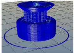
[image:3.612.204.410.306.415.2]The process starts by designing 3D CAD model of a object to be printed in any CAD tool such as AutoCAD as shown in figure 9. Then these 3D models are opened in host application using stereo lithography (.stl) file format. There are lots of open source host application softwares are available.
Figure 2: CAD model of 3D object to be printed (Pulley)
B. Firmware Uploading
Once CAD model is ready, printer should be connected using printer control board to computer and upload the modified firmware into microcontroller. There are many open source firmware available. Repetier firmware is very famous and compatible with many boards, so Repetier is used after modifying it with Cartesian to cylindrical conversion for 3D Potter. The Firmware is heart of Printer Board which controls precise motion of all stepper motors according to g-code data.
C. Connecting Printer To Host Application
Then we have to connect the printer to computer using the host application via USB port. Here we have to set required connection settings such as baud rate etc. Once Printer is connected to computer we can control printer head through application. Then we set the head position at home where we intend to start the printing on printing bed.
D. Slicing The 3D Model And Start Printing
There are different slicing methods such as concentric, honeycomb, rectilinear etc. Slicing is method of splitting CAD models into layers with some defined set of structure. Then we slice the 3D model into digital cross-sections for the machine to successively use as a guideline for printing as shown in figure 10
[image:3.612.246.365.619.704.2]Technology (IJRASET)
After slicing is done we have set feedrate, flow rate etc. Then we can start printing the object.As we can see in case of circular shaped object like pulley shown in figure 9, it’s easy for Potter to print object, because for one layer which is circle radius is fixed for all points on circle just angle changes. So Printer head has to move only once to adjust the radius and then Y bed which is circular in case of Potter will rotate for whole 360 degree to print circle. So here we are reducing printer head motion which can give good printing speed thereby reducing print time.
E. Software
Now that you have a background on the electronic hardware, the steps of 3D printing software can be introduced. 3D printing software allows you to create, view, and alter 3-D images, converts the image into instructions for the printer, and "slices" the file into horizontal pieces that the printer will understand the printer deposits plastic in horizontally. The workflow for turning an idea into a 3D print can be summed up as creating a model, slicing, and printing. At each step, there are multiple software solutions to choose from. In general, for 3D printing software can be broken down into 3 different areas, CAD tools, CAM tools, and firmware for electronics.
F. CAD Tools
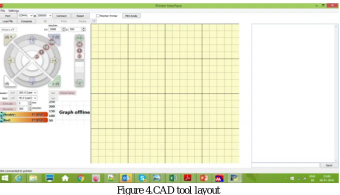
[image:4.612.138.478.449.644.2]Computer Aided Design, or CAD, tools are used to design 3D parts for printing. CAD tools allow you to easily change and manipulate parts based on parameters. One of the techniques used in solid modeling CAD tools is called Constructive Solid Geometry, or CSG. Using CSG, parts can be represented as a tree of Boolean Operations performed on basic shapes such as cubes, spheres, cylinders, and pyramids to create complex surfaces. For example, a hollow ball can be modeled by drawing two overlapping spheres, one lightly smaller than the other and subtracting the smaller from the larger. Simply CSG presents a model or surface toappear visually complex, but it is merely a combination of objects. Open Source Software applications for CAD are OpenSCAD, FreeCAD, SketchUp, and HeeksCAD. Examples of proprietary CAD tools are Solidworks and Autodesk Inventor. The next step in turning a model from CAD is generating it into an STL file. Most 3D software applications save their files in an application-specific format, but there are very few interchangeable CAD file formats. The two most widely used interchangeable CSG file formats that should not be used are STEP and IGES, because both strip the geometries from data and create flat solids. The ideal file used to export a 3D model is an STL file. STL files can be generated from CAD, these STL files can be sliced and printing unlike STEP and IGES files. One of the most common mistakes for beginner users is not using the correct file type so it’s a good idea to design it using a CSG CAD application and save the original parametric file along with generated STL files.
Figure 4.CAD tool layout
G. CAM Tools
Technology (IJRASET)
code, you use a slicing program. Some examples of slicing programs include Slic3r, Kisslicer, RepSnapper, and RepRap Host Software. The process of converting STL to G-code slices the model, then looks at the cross section of each slice and figures out the path that the print head
H. Result
Finally the design implement to the processor then the printer print the object .now we get the object.
IV. CONCLUSION AND FUTURE WORK
This Paper implemented a high-end technology of 3-D printing, which could prove to be a milestone in the field of die making. The final implementation provides a very cost effective and feasible solution to 3-D printing, making it more viable to consumers and opening a wide area of development in this field. The development of this 3D Printer gave a greater insight towards a low cost system which could prove so much useful for preparing a die.
Though, this 3D Printer did require overcoming some challenges, like the modeling needed some pretty tough mathematical calculations, and some trial and error methods. After some breaking and some re-assembling, when the mechanical chassis and the structure were ready, the main problem came into picture. The movement of the extruder required up to 5 different stepper motors to be moved simultaneously, which in turn needed 5 motor drivers. Controlling them through g-codes required thorough understanding of Marlin software and the code sequences, this, proved to be quite useful, at the later stages of the development.
But, once the whole structure and the program were ready, it was able to print dies successfully, and according to the demanded specifications. Though there are many features that can be added, and this would be a never ending field of research, the objective of the dissertation limits the scope to what was implemented, and proposes it as a low cost solution in manufacturing die and other such jobs/products. REFERENCES [1] http://arduino.cc/en/Main/arduinoBoardMega2560 [2] http://www.wvshare.com/datasheet_html/L293D-PDF.html [3] http://www.ti.com/lit/ds/symlink/l293d.pdf [4] http://www.parallax.com/sites/default/files/downloads/27964-Stepper-Motor-Documentation.pdf [5] http://www.omega.com/auto/pdf/REF_IntroStepMotors.pdf
[6] ”Printing Embedded Circuits” Periard D., Malone E., Lipson H., (2007) , Proceedings of the 18th Solid Freeform Fabrication Symposium, Austin TX, Aug 2007, pp.503-512.
[7] "Design in the age of 3D printing, Lipson, H. (2012) Thinking outside the CAD Box", Mechanical Engineering, September 2012, pp. B - G. [8] “Advanced technology and market trend of printed electronic (1sted.)”, Korean Scientist and Engineers Network. (2011) South Korea: Kim, S. H.
[9] “Printable Materials and Printing Technology Road Map (1sted.)”, Korea Environmental Nano Research Center. (2010). South Korea: Kim, N. S., Oh, D. H., Lee, Y. J., Lee, J.H., Jo, Y. K., Hwang, J. H., and Hong, S. I.
[10] “The difference between ABS and PLA for 3D printing”. Chilson, L. (Jan. 27, 2013). Retrieved from http://www.protoparadigm.com/blog/2013/01/the-difference-between-abs-and-pla-for-3d-printing.