5
X
October 2017
PSCAD Simulation Model of 12 Pulse DSTATCOM
for Voltage Sag Improvement
Paras Gaur1, Pankaj Chaudhary2, Harsh Patel3
1, 2, 3
School of Electrical Engineering (Select),Vellore Institute of Technology(Chennai),Tamil Nadu 600127
Abstract: This paper describes the modeling, simulation and analysis of 12-pulse distribution static compensator (D-Statsom) for voltage syringe. Simulation of D-STATCOM was done using Power System Computer Aided Design (PSCAD) software. The power distribution system or facilities in the plants are due to the voltage. Simulation results prove that D-STATCOM is capable of reducing voltage seg and improving the power quality of the distribution system.
Keywords : Voltage sag, Distribution line,12 pulse D-STATCOM,Power Quality, PSCAD
I. INTRODUCTION
Power distribution system is a part of the electrical system between power sources and end users. Wholesale energy sources are located very far from the load center and provide the service to the consumer through the distribution system. Due to the heavy burden in the demand of the consumer side in the modern era, the demand for reliable power has been kept in mind with high quality, reliable ideas. Distribution systems in the modern industries include the use of non-linear and electronically switched devices.Today, the whole world facing the problem of power quality is an imbalance of voltage bag, voltage spell, flicker, harmonics, voltage imbalance, active and reactive power and low power factor. This may have an impact on power supply, which could affect the manufacturing industry and inhibit economic development in any country.[1][2]Voltage sags are from 10% to 90% nominal voltage of magnitude. 12 pulse DSTATMOM is applied to reduce voltage sags in the distribution line, thus improving the power transfer capacity. DSTATAPM generates and absorbs reactive power at a fast speed because there is no moving part involved and it goes well with energy storage facilities, which opens the opportunities for other applications like energy market and security.There are several such papers that have been published to improve the quality of the power, the effectiveness of D-statom, especially voltage sags.
II. RELATEDKNOWLEDGE
A. Review on Power Quality Issues
Power quality is a set of power boundaries, which allows a piece of equipment to work in its desired way without significant performance or without any significant loss of life expectancy. All electrical equipment failure occurs when one or more electrical quality problems are exposed.Electrical equipment can be an electric motor, transformer, generator, computer, printer,
communication device or home appliance. Based on the severity of all these devices and other problems, adverse reactions to the quality of power[3]
Without proper power, an electrical device can get spoiled, may fail before prematurely or does not work at all. There are many ways in which electrical power can be of poor quality and there may be many other reasons for such poor quality powers. Some of the most common power supply problems are voltage spikes, voltage dumps, harmonic deformation, voltage imbalances, flicker, transients.The increase in voltage bag load, such as short circuits or defects, the start of motors or electric heaters are on, or they are due to the sudden increase in the source impedance, usually due to the loose connection.
To improve the quality of electricity in both volts, at least for those customers who work with the processes of susceptible to voltage acids and small blockages, currently based on traditional technology improvements in the market or the electricity semiconductor Offers a wide range of products on the use of conversion techniques.[4]
To overcome Sags problem, shunt and series devices are generally applicable to the system. Therefore, this letter implements 12 pulse DSTATMOM using 6 Pulse D STATCOM technology and using PSCED. Then, during the mistake it is done for analysis during the before and after application.
B. Basic Configuration and Operation of D-STATCOM
D-STATCOM is a three-phase and shunt connected power electronics-based device. It is connected to the load on delivery systems.
DC voltage into three phase output voltage at the fundamental frequency. These voltages are controlled in phase and the coupling gets connected with the AC system through the transformer.[5]
Fig. 1 Basic structure of STATCOM
III. METHODOLOGY
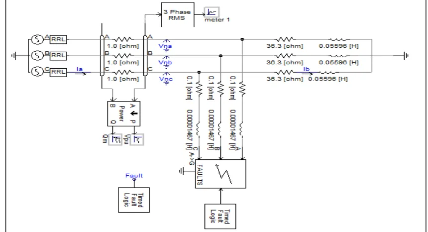
A distribution line has a line-to-line voltage, 11 kV is loaded with 1MVA, which was designed to be 0.9 power factor hang. The voltage source will act as the secondary part of the transformer and is directly linked to the Y-connected load of three steps. Load impedance is calculated by considering only one step.
Therefore, using the values given earlier, the value for load resistance is 36.3, while the value for the load installation is 0.05596 HK. For this research, two 6 pulse DSTATCOM connected to parallel is used. Power switches are due to the ability to turn off and turn on positive point signal due to the turn-off throrist (GTO). To maintain the load voltage is kept 1PUU, then PI controller is used to control GTO.In addition, the PWM switching method is also applied to generate three phase 50Hz sinusoidal voltage. Figure 2 shows the test system with the fault model in PSCD before the application of 12-pulse DSTATCOM. Depending on the data, fault generator blocks are created in PSCAD. After this, the fault of the land fault and the three-step fault is included in the system and the injection is done.After this, 12 pulse DSTATAPM is applied and the model of the picture system is connected in parallel to the model as shown in Figures 3,4.
Fig. 4 Control circuit of D-STATCOM
IV. SIMULATIONRESULTSANDDISCUSSION
A.Simulation with Fault without DSTATCOM
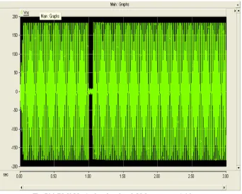
The distribution system, which included three-phase balanced defect, was simulated for two seconds. The voltage was loosely at 0.66 seconds for 1.06 seconds. Actual and reactive power meters are used to measure actual and reactive power in the distribution line system. Reactive during a single phase fault in land, it is classified as a line on the ground. The three-phase system is one of the most common disadvantages in the same row.On the basis of test systems, a single fault line is assumed that the phase which touched the ground, since the system could not be loaded prior to the loss.The voltage is the percentage of the sig position and the delivery phase system has three phase balanced fault. Illustrated diagrams as figures show that VRMS voltage decreases from 0.959 to 0672 per unit. This means that the total loss in the input voltage is one phase for the ground, 30% of the total deficit in the input voltage is one step on the ground. Changing the fault impedance can change the depth of procrastination. Next, three phase errors have been created.The result in Figure 5 shows that the voltage is looser and the system bothers. This time, the VRMS voltage decreased from 0.959 to 0.052 per unit. This means that the total loss in the input voltage is the basis of the ABC phase, because 94.6% of the total loss in the input voltage is ABC phase on the ground.
[image:5.612.139.481.281.555.2]
Fig.5(b).Reactive power’s graph Fig.5(c) P’s output overlay graph
Fig.5(d) Vna’s Overlay graph
Fig.5 Voltage, Real Power and Reactive Power under Voltage Sag condition
B.Simulation with Fault with STATCOM
.
Fig.6 Simulation with Fault with 12-Pulse STATCOM
V. CONCLUSIONS
Voltage seg problems have been resolved using D-STATCOM. Simulation model of 12-pulse D-STATOMM has been prepared using PSCAD / EMDTC software. From the result obtained, the 12-pulse DSTATCOM reduces and compensates for a single line voltage looser for ground fault and three-phase fault without any difficulty.
The performance of the power system with the installed factories in it is better than the performance of the power system, without the installed equipment in it. The problem of power quality can not be completely eliminated, but it can be reduced so that the result of this problem is as minimal as possible.
REFERENCES
[1] Belkacem Mahdad, Tarek Bouktir, Kamel Srairi, “Strategy of Location and Control of FACTS Devices for Enhancing Power Quality”, IEEE MELECON, pp 1068-1072, 2006.
[2] IEEE Transaction ON Power Delivery, VOL. 17, NO. 1, January 2002, ―Modelling and Analysis of Custom Power Systems by PSCAD/EMTDC‖ by Olimpo Anaya-Lara and E. Acha.
[3] A. Hernandez, K. E. Chong, G. Gallegos, and E. Acha “The implementation of a solid state voltage source in PSCAD/EMTDC,” IEEE Power Eng. Rev., pp. 61-62, Dec 1998.
[4] Youjie Ma, Ahui Huang, Xuesong Zhou, “A Review of STATCOM on the Electric Power System”, IEEE Proceedings International Conference on Mechatronics and Automation, pp. 162-167, 2015.
[5] D.K. TANTI1, BRIJESH SINGH2, DR. M.K. VERMA3, DR. O. N. MEHROTRA “An ANN Based Approach for optimal placement of DSTATCOM for Voltage Sag mitigation” International Journal of Engineering Science and Technology (IJEST)