Designing of 128-Bit ALU (Arithmetic Logic Unit)
using VHDL
Kapil1, Ramnish Kumar2 1
Student, M.Tech (ECE), GJUS&T, Hisar
2
Asst. Professor, ECE, GJUS&T, Hisar
Abstract: The VHDL (Very high speed integrated circuit Hardware Description Language)is a very popular tool for designing the digital system. In this paper, a VHDL design of 128-bit Arithmetic Logic Unit (ALU) is simulated. MainlyALU is the basic and fundamental unit of amicroprocessorwhich implements all the elementary operations established on the control input selection (Select Line).ALUlook-like a multiplexer which perform all the operations on the base of select lines. The ALU performs the addition, subtraction, comparison and all the logic operations using Xilinx ISE 8.1i tool. Here a mixed modeling of VHDL is used for implement and synthesis ALU which includes both logical and arithmetic operations.
Keywords: -VHDL, ALU, Xilinx ISE 8.1i, mixed modelling
I. INTRODUCTION
The VHDL is a hardware description language used for analysis and synthesis of digital circuit. Now it is a standard by IEEE and appropriated by various FPGA and ASIC vendors.VHDL does not stand for any simulation control or monitoring skill within the language. These skills are tool dependent. There are many design automation tools which support VHDL have been developed by CAD (Computer Aided Design)engineering companies. Generally, VHDL language is operated by the two main tools i.e. simulation and synthesis.
II.ALU
An arithmetic logic unit (ALU) as shown in fig. 1 is a multi-operated device which performs combinational-logic digital function with a set ofbasic arithmetic operations as well as logic operations. These two operations are depends upon the number of selection lines to select a particularoperation in the unit. Mainly ALU contains two inputs which are control by the select line for the multi-operation. ALU defines for the two most important units and they are arithmetic and logic units. In this paper, the arithmetic unit defines for the 128-bit adder, 128-bit subtractor and 128-bit comparator where in the logic units we define all the gates of 128-bit.
A. Arithmetic Unit
The arithmetic unit responsible for the mathematic calculation. There are various types of arithmetic operations e.g. Addition, subtractions, comparison and they are details as:-
1) Adder: The simplest 1-bit adder calculates the output in term of the carry out and sum so, the relationship between input and output is defined below:
Sum =A XOR B XOR Cin (1)
Cout = (A.B) OR (B.Cin) OR (A.Cin) (2)
Where A and B are inputs and Cin is carry input.
The adder have many types on the basis of their performance. In this paper, we use the Carry Look ahead Adder (CLA) which is faster one. The ripple-carry adder has a limiting factor of the time that it take to propagate the carry. The Carry Look-ahead Adder (CLA) removed this limiting factor by calculating the carry signals in advance, based on theinput signals. This result reduces the
carry propagation time in term of carry propagate (Pi) and carry generate (Gi) and where Pi and Gi are:-
Pi = (Ai) XOR (Bi) (3)
Gi =(Ai).(Bi) (4)
2) Subtractor: Subtractor is the digital circuit which is used for subtract two binary numbers (digit) and provides difference and borrow out as an output.
D = (AXOR B)XOR Bin (5)
Bout=((NOT A).B) OR (B.Bin) OR ((NOT A).Bin) (6)
Where A and B are inputs and Bin is borrow input
Figure 1. Block diagram of ALU
B. Logical Unit
In this unit, the logic operations are performed. Here two different inputs are feed at input and at the output we will obtained the logical output. In digital system there are seven gates which performs the various logics and they are OR, AND, NOT, XOR, XNOR, NAND and NOR gate. The logic unit defines the logic level of the signals. It defines the signal on the two levels i.e. high level and low level. Mainly high level for ‘1’ and low level for the ‘0’.
C. Xilinx Simulation
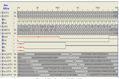
Simulation of 128- Bit ALU for the mixed model has been performed for 1000 nano-seconds (ns). Each Clock cycle has 10 ns rise time and 10 ns fall time. The simulation of 128-Bit ALU (if rising edge (CLK) =0). This RTL is generated by the Xilinx simulation. The fig. 2 shows the RTL view. Also the waveform is generated by the software with the help of the testbench. The waveform is shown in fig.3. In this simulation the spartan3 family is consider and the device is xc3s200 as well the package is FT256 and the speed is taken of -4.
[image:3.612.208.402.501.717.2]Figure 3. Waveform for 128-Bit ALU
The fig.3 shows the waveform where a and b are input bits of 128 bit. The select line selects the particular logic and it is indicated by sl. The input carry and borrow are shown by cin and bwin respectively and the outputs of adder are sum and cout (carry out)
andoutput for subtractor are diff. and bwout (borrow out).Where the comparator output shown by less, gr (greater) and eq (equal) and
the last seven outputs are logic output. The undefined line takes place because there is no action consider by the program.
[image:4.612.165.446.444.536.2]III. RESULT
Table 1. 64-Bit ALU
Logic Utilization Used Available Utilization
No. of Slices 857 960 89%
No. of Slice Flip-Flop 65 1920 3%
No. of 4 input LUTs 1521 1920 79%
No. of bounded IOBs 279 108 258%
No. of GCLKs 1 24 4%
The 64-bit ALU shows the details in table 1 and in fig. 4 which is conventional result. The bar graph shows the highest peak of No. of bounded IOBs is 258 % whereas lowest peak is of No. of slices flip-flop is 3 %.
Figure 4: Utilization of 64-bit ALU
89% 3% 79%
258%
4% 0%
100% 200% 300%
No. of Slices No. of Slice Flip-Flop
No. of 4 input LUTs
No. of bounded IOBs
No. of GCLKs
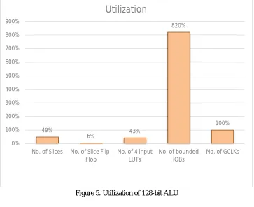
[image:4.612.122.493.580.701.2]Table 2. 128-Bit ALU
Logic Utilization Used Available Utilization
No. of Slices 946 1920 49%
No. of Slice Flip-Flop 255 3840 6%
No. of 4 input LUTs 1678 3840 43%
No. of bounded IOBs 1419 173 820%
No. of GCLKs 8 8 100%
[image:5.612.125.488.245.541.2]The 128-bit ALU shows the details in table 2 and in fig. 5 which is proposed result.The bar graph shows the highest peak of No. of bounded IOBs is 820 % whereas lowest peak is of No. of slices flip-flop is 6 %. This huge difference made because of the no. of bit is doubled.The no. of bounded IOBs just detailed about the no. of input and output which are considered while it is programmed.
Figure 5. Utilization of 128-bit ALU
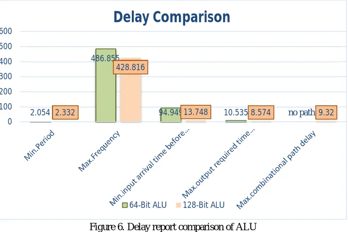
Table 3. Delay report comparison of ALU
49%
6% 43%
820% 100% 0% 100% 200% 300% 400% 500% 600% 700% 800% 900%
No. of Slices No. of Slice Flip-Flop
No. of 4 input LUTs
No. of bounded IOBs
No. of GCLKs
Utilization
Parameter 64-Bit ALU 128-Bit ALU
Min.Period 2.054 ns 2.332 ns
Max.Frequency 486.855 Mhz 428.816 Mhz
Min.input arrival time before clock 94.949 ns 13.748 ns
Max.output required time after clock 10.535 ns 8.574 ns
Figure 6. Delay report comparison of ALU
IV. DISCUSSION
The delay report comparison between64-bit and 128-bit of ALU is shown in fig.6 and in table 3. We can conclude that the delay of 128-bit ALU is much betterthan 64-bit. Also the no. of 4 input LUTs and no. of slices also better then that of 64bit ALU. It is obvious that as we increase the no. bit then the no. of bounded IOBs will increse.
V. CONCLUSION
The 64 bit ALU is designed and synthesized using Xilinx ISE v8.1i and targeted to Spartan 3 device. TheALU is a very important part of the CPU (Central Processing Unit). Its arithmetic unit performs theAddition, Subtraction, Comparator and all basic logical operations (AND, OR, NOT, NOR, XOR,XNOR, NAND). We analysed the results from Xilinx ISE Design Suit v8.1i with the theoreticalresults for all the operations that were performed and found that they ideal with the theoretical result.
REFERENCE
[1] Prachi Sharma, Rama Laxmi, Arun Kumar Mishra “A Review: Design of 16 bit Arithmetic and Logical unit using Vivado 14.7 and Implementation on Basys 3 FPGA Board”International Journal for Research in Applied Science & Engineering Technology (IJRASET)Volume 4 Issue VIII, 2016.
[2] Mukesh P. Mahajan, P. G. Salunke, Y. M. Gaikwad, V. P. Jagtap “Design And Simulation of 64-bit ALU” International Journal of Advanced Research in Electronics and Communication Engineering (IJARECE) Volume 4, Issue 4, 2015.
[3] Daljit Kaur, Ana Monga “Performance Analysis of 64-Bit Carry Look Ahead Adder”(IJCSIT) International Journal of Computer Science and Information Technologies, Vol.5 (1), 2014.
[4] T. Dinesh kumar,M. Arunlakshman,“A Strategical Description of Ripple Borrow Subtractor in Different Logic Styles”,International Journal of Engineering Research and General Science Volume 2, Issue 3, 2014.
[5] Saumyakanta Sarangi, Sangita Swain, Swagatika Dash, Manas Ranjan Mohanta “VHDL Implementation of Arithmetic Logic Unit” International Journal of Engineering Research & Technology (IJERT)Vol. 3 Issue 4, 2014.
[6] Archana Singh Yadav, Pratyush Tripathi “A VHDL Implementation of a Flexible 16-Bit Arithmetic and Logical Unit” International Journal of Engineering Research &Technology (IJERT)ISSN: 2278-0181Vol.3 Issue 4, 2014.
[7] Kavita Katole, AShwin Shinde, Sumedha Chokhandre, Nirja Dharmale,Bhushan Manjre “Design& SImulation OF 32-bitFloating Point ALU” International Journal of Advances in Science Engineering and Technology, ISSN: 2321-9009 Volume- 2, Issue-2,2014.
[8] Rajib Chetia, Kaushik Chandra Deva Sarma, Gaurab Baruah “Behavioral Design and Synthesis of 64 BITALU using Xilinx ISE”IOSR Journal of Electronics and Communication Engineering (IOSR-JECE) e-ISSN: 2278-8735. Volume 7, Issue 4, 2013.
[9] P Bhanusree, G Bhargav Sai, Y Ashwanth Kumar and K Sravan Kumar “VHDL Implementation Of 64-bit ALU”IOSR Journal of Electronics and CommunicationEngineering (IOSR-JECE) e-ISSN: 2278-2834,p- ISSN: 2278-8735.Volume 7, Issue 4,2013.
[10] Rajender Kumar, Sandeep Dahiya “Performance Analysis of Different Bit Carry Look Ahead Adder using VHDL environment” International Journal of engineering Science and Innovation and Technology (IJESIT) Volume 2, Issue 4, 2013.
[11] Rajeev Kumar, Manpreet Kaur(2012) “Design & Implementation of 64 bit ALU for Instruction Set Architecture & Comparison between Speed/Power Consumption on FPGA” International Journal of Advanced Research in Computer Engineering &Technology Volume 1, Issue 4, 2012.
2.054
486.855
94.949 10.535 no path
2.332
428.816
13.748 8.574 9.32
0 100 200 300 400 500 600
Delay Comparison
Technique” International Journal of Modern Engineering Research (IJMER) Vol.2, Issue.4, 2012, pp-2695-2698.
[13] Shikha Khurana, Kanika Kaur “implementation of ALU using FPGA”International Journal of Emerging Trends & Technology in Computer Science (IJETTCS) Volume 1, ISSN 2278-6856,Issue 2, 2012.
[14] Geetanjali and Nishant Tripathi “VHDL Implementation of 32-Bit ArithmeticLogic Unit (ALU)”International Journal of Computer Science and Communication Engineering IJCSCE Special issue on “Emerging Trends in Engineering” ICETIE 2012.
AUTHORS
Kapil, He received his B.Tech in Electronics and Communication Engineering from O.I.T.M., Hisar, Haryana and pursuing M.Tech in Electronics and Communication Engineering from Guru Jambheshwar University of Science and Technology, Hisar, Haryana, India. His area of interest is in Digital Electronics and VHDL simulation.