5
IV
April 2017
Technology (IJRASET)
©IJRASET: All Rights are Reserved
739
An Efficient Image Compression using Discrete
Cosine Transform with SIFT and Modified
Colorization Channel
Gaurav Kumar1, Prof. Durgesh Wadbude2
1
PG Scholar, 2HOD (CSE), Mittal Institute of Technology, Bhopal
Abstract : We propose a novel compression scheme for digital images using chrominance channels with feature descriptor and Discrete Cosine Transform (DCT). The feature descriptor of chrominance channel is based on their error metrics. We describe an input image based on its down-sampled version and local feature descriptors. The chrominance channel descriptors are used to retrieve feature descriptive images and identify corresponding patches. The down-sampled image serves as a target to stitch retrieved image patches together. The feature vectors of local descriptors are predicted by the corresponding vectors extracted in the decoded down-sampled image. The image is transformed by using DCT and then the rank is being reduced by ignoring some of the lower singular values as well as rows of hanger and aligner matrices. Experimental results demonstrate the effectiveness of the proposed scheme. The overall compression process supports to reach a acceptable level for image transmission in limited bandwidth over a telecommunication medicine application. We analyzed the performance of image compression technique using metrics Colorization Level (CL), Compression Ratio (CR), Peak Signal to Noise Ratio (PSNR), Visual Signal to Noise Ratio (VSNR), Multi-Scale Structural Similarity Index (MSSIM) and Noise Quality Measure (NQM).
Index words: Colorization Level (CL), Compression Ratio (CR), Peak Signal to Noise Ratio (PSNR), Visual Signal to Noise Ratio (VSNR), Multi-Scale Structural SIMilarity Index (MSSIM) and Noise Quality Measure (NQM).
I. INTRODUCTION
With the arrival of the internet and the multimedia age, the number of images available online has grown rapidly, and there is an increasing demand for better image compression techniques. Typically, there is a lot of redundancy in the image data (e.g., the nearby pixels are usually correlated). With a sophisticated compression algorithm, we can greatly reduce the space required to store an image. Classical image compression algorithms (e.g., JPEG) transform the image from a spatial domain representation to a frequency domain representation and use a carefully designed encoding scheme to store the coefficients of the frequency domain. At the decoding stage, the frequency coefficients are recovered and transformed back into the spatial domain to get the normal image pixel data. Recently, earlier proposed technique to solve the image compression problem with machine learning techniques and achieved impressive results.
In order to improve the quality metrics of the transformed image, a total error minimization with compensate scheme is to be implemented [1]. The performance of the compression scheme can be increased by using feature descriptor and singular value decomposition method. Another possibility for improving the performance would be to use feature-based and adaptive approaches. The performance for lossless compression techniques can also be improved by performing different combinations of various transforms and coding techniques involving DCT and predictive coding that realize the most optimal combination that gives the feature descriptor. We focus on the following issues.
Improve Compression Ratio as compare than TEM-C. Increase Colorization Level as compare than TEM-C. Decrease MSE as compare than TEM-C.
Increase PSNR as compare than TEM-C. Improve VSNR as compare than TEM-C. Improve MSSIM as compare than TEM-C. Improve NQM as compare than TEM-C.
Technology (IJRASET)
©IJRASET: All Rights are Reserved
740
Total Error Minimization – CompensateTotal Error Minimization
Graph Regularized Experimental Design Cheng’s Technique
II. RELATED WORK
Zhan et al [1], the special techniques of radar imaging, SAR images have some distinct properties when compared with natural images that can affect the design of a compression method. First, we introduce SAR properties, sparse representation, and dictionary learning theories. Second, we propose a novel SAR image compression scheme by using multi-scale dictionaries.
Kahu et al [2], The Discrete Wavelet Transform expresses image data in terms of number of eigen vectors depending upon the dimension of an image. The psycho visual redundancies in an image are used for compression. Thus an image can be compressed without affecting the image quality.
Yue et al [3], It no longer compresses images pixel by pixel and instead tries to describe images and reconstruct them from a large-scale image database via the descriptions. First, we describe an input image based on its down-sampled version and local feature descriptors. Second, the down-sampled image is compressed using current image coding. The feature vectors of local descriptors are predicted by the corresponding vectors extracted in the decoded down-sampled image. The predicted residual vectors are compressed by transform, quantization, and entropy coding.
Zhang et al [4], the compression involves storing only the grayscale image and a few carefully selected color pixel seeds. For decompression, regression models are learned with the stored data to predict the missing colors. This reduces image compression to standard active learning and semi-supervised learning problems.
Ryu et al [5], the encoder makes use of the meanshift segmentation algorithm in automatically selecting the representative pixels from the original image from which the colored image is reconstructed by the decoder. Using the modes of the clustered regions as there preventative pixels, the compression rate becomes high and there constructed image has good visual quality.
III. PROPOSED METHODOLOGY
In following, explain the main processes of the proposed discrete cosine transform with scale invariant feature transform (DCT-SIFT) method.
The Algorithm of proposed method is explained below: [compress_image]=DCT_SIFT (source_image)
Step 1: Consider the source_image as RGB form with specific resolution.
Step 2: Convert RGB source_image into YCbCr form (Luminance and Chrominance Channel)
Step 3: Extract luminance channel from YCbCr image with set the value of chrominance channels as zero. Step 4: Similarly extract chrominance channel from YCbCr image with set the value of luminance channel as zero.
Step 5: Find keypoint descriptor of chrominance channel using SIFT (Scale Invariant Feature Transform) methods. The SIFT technique can be implement in following four steps.
A. Scale-Space Extreme Detection
The initial step of evaluation finds total all scale-space and different image area in image dataset nodes [4]. It is completely apply effectively by using a Difference-of-Gaussian (DoG) mapping to represents potential interest keypoints of feature descriptors which are scale invariant and orientation in image dataset nodes [6].
B. Keypoints Localization
All candidate area of image in selected ROI (Region of Interest), a detailed prototype is fit to analyze keypoints area and its scale-space [5]. Keypoints of image area in image ROI are chooses basis on calculate of existing stability [6].
C. Orientation Assignment
Technology (IJRASET)
©IJRASET: All Rights are Reserved
741
D. Keypoints DescriptorThe local image gradients value are measured at the choose scale-space in the Region of Interest (ROI) around all keypoints in image dataset points [4]. These are transformed into a presentation that permits for significant levels of local shape, location and orientation and changes in illumination of image dataset points [6].
Step 6: Above step are perform in repeated form, then all the descriptor of chrominance channel are store, Now calculate error metric on the basis of chrominance channel and feature descriptors of chrominance channel.
Step 7: Now add error metrics with luminance channel and update value of luminance channel. Step 8: Convert YCbCr image into RGB image.
Step 9: Now perform DCT process for compression, input image is considered as an array of integers. Step 10: The DCT process perform IN Three steps
E. JPEG Process
1) Original image is divided into blocks of 8 x 8.
2) Pixel values of a black and white image range from 0-255 but DCT is designed to work on pixel values ranging from -128 to 127. Therefore each block is modified to work in the range.
3) Following equation is used to calculate DCT matrix.
1 1 0 0
( , )
( ) ( )
( , ) cos[(2
1)
/ 2 ]cos[(2
1)
/ 2 ]
N N
x y
C u v
D u D v
f x y
x
u
N
y
v
N
Where u, v = 0, 1, 2, 3, ..., N-1where ,D(u)=(1/N)^1/2 for u=0 D(u)=2(/N)^1/2 for u=1,2,3...,(N-
4) DCT is applied to each block by multiplying the modified block with DCT matrix on the left and transpose of DCT matrix on its right.
5) Each block is then compressed through quantization. 6) Quantized matrix is then entropy encoded.
7) Compressed image is reconstructed through reverse process.
F. Quantization
Quantization is achieved by compressing a range of values to a single quantum value.
G. Entropy Encoding
After quantization, most of the high frequency coefficients are zeros. To exploit the number of zeros, a zig-zag scan of the matrix is used yielding to long string of zeros. Once a block has been converted to a spectrum and quantized, the JPEG compression algorithm then takes the result and converts it into a one dimensional linear array, or vector of 64 values, performing a zig-zag scan by selecting the elements in the numerical order indicated by the numbers in the grid.
Step 11: Finally obtain the compressed image.
IV. IMPLEMENTATION STEP
Technology (IJRASET)
©IJRASET: All Rights are Reserved
742
Fig 2: Source Images (a) baboon 500x480 (b) man 256x384 (c) bus 256x384 (d) pepper 512x512 (e) bird 384x256Image Quality is a characteristic of an image that measures the perceived image degradation (typically, compared to an ideal or perfect image). Imaging systems like the compression algorithm may introduce some amounts of distortion or artifacts in the signal, so the quality assessment is an important problem. Image Quality assessment methods can be broadly classified into two categories: Full Reference Methods (FR) and No Reference Method (NR). In FR, the quality of an image is measure in comparison with a reference image which is assumed to be perfect in quality. NR methods do not employ a reference image. The image qualities metrics considered and implemented here fall in the FR category. In the following subsections, we discuss the MSSIM and some other image quality metrics implemented to assess the quality of our compressed image.
A. Mean Squared Error B. Peak Signal to Noise Ratio C. Visual Signal to Noise Ratio
D. Multi-Scale Structural Similarity Index Measure E. Noise Quality Measure
F. Compression Ratio G. Colorization Level
V. RESULT ANALYSIS
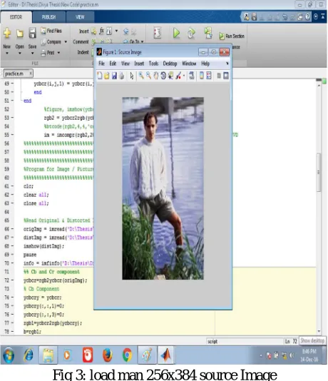
[image:5.612.191.421.409.676.2]At beginning, we take source image with specific size and format. For this purpose, imread() use for read the source image from required path.
Fig 3: load man 256x384 source Image
Technology (IJRASET)
©IJRASET: All Rights are Reserved
743
Fig 4: Compressed Image obtained from proposed methodSource image and compressed image are used for calculate the MSE, PSNR, MSSIM, VSNR, NQM, CL and CR. These performance parameters is use for compare the evaluate value from source images and compressed image. These values are evaluates for source image and compressed image.
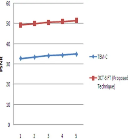
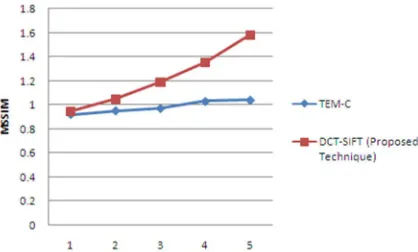
[image:6.612.202.415.81.239.2]If image size is taken as 256x384, 500x480 and 512x512 then the analysis of the existing work (TEM-C) and the proposed work (DCT-SIFT) on the basis of different quality parameters are given in Table 1.
Table 1: Analysis of comparisons the value of PSNR, VSNR, MSSIM, NQM in between of TEM-C and DCT-SIFT with image size 256x384.
[image:6.612.204.410.470.693.2]Technology (IJRASET)
©IJRASET: All Rights are Reserved
[image:7.612.211.420.232.358.2]744
Fig 6: Comparison of VSNR for image size 256x384[image:7.612.203.414.388.513.2]
Fig 7: Comparison of MSSIM for image size 256x384
Fig 8: Comparison of NQM for image size 256x384
Technology (IJRASET)
©IJRASET: All Rights are Reserved
[image:8.612.200.414.386.513.2]745
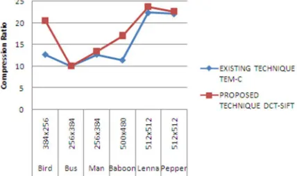
Fig 9: Comparison of PSNR for different image sizesTable 3: Analysis of comparisons the value of Compression Ratio in between of TEM-C and DCT-SIFT for different image sizes.
Fig 10: Comparison of Compression Ratio for different image sizes
[image:8.612.190.426.540.698.2]
Technology (IJRASET)
©IJRASET: All Rights are Reserved
746
Fig 11: Comparison of Colorization Level for different image sizesHere the comparisons result tested on the basis of different image size and measure the various result parameters shown in the comparisons tables. The compressed image is compares in between of TEM-C and DCT-SIFT for different image sizes (in Table 1, 2, 3 and 4). The value of PSNR (for DCT-SIFT) is more than value of PSNR (for TEM-C). The value of VSNR (for DCT-SIFT) is more than value of PSNR (for TEM-C). The value of MSSIM (for DCT-SIFT) is more than value of MSSIM (for TEM-C). The value of NQM (for DCT-SIFT) is more than value of NQM (for TEM-C). The value of CL (for DCT-SIFT) is more than value of CL (for TEM-C). Hence the performance of the proposed work is better as compared to the existing technique.
VI. CONCLUSIONS
The proposed method is DCT-SIFT algorithm for image compression. The key advantage over previous methods comes from the maximum exploitation of the full label set (i.e., the colors for all the pixels) at the encoding stage. Furthermore, DCT-SIFT used the label set to generate and store a difference image for correcting the prediction error and improved the colorization quality significantly. Experimental results demonstrated the outstanding performance of the proposed methods. Although the computation burden is still high, DCT-SIFT already competitive to the industrial standard JPEG in image quality and compression ratio.
This work proposes a feature descriptors image coding scheme, where images are described by SIFT descriptors. The SIFT descriptors are compressed by DCT and transform coding. Finally, high quality and high-resolution images are reconstructed from a set of images by the proposed description. Experimental results show that the proposed scheme achieves high compression on average but also gets high subjective scores.
VII. SCOPE OF FUTURE WORK
The performance of the algorithms can be improved by introducing the directional oriented multi-resolution transforms such as steerable pyramids, contour-lets etc and shift invariant transforms such as un-decimated wavelet transforms and complex wavelet transforms in the multi-resolution decomposition stage. We can use SURF (Speeded up Robust Feature), CHoG (Compressed Histogram of Gradient) for find the feature descriptor of image texture.
REFERENCES
[1] Xin Zhan, Rong Zhang, Dong Yin, and Chengfu Huo, “SAR Image Compression Using Multiscale Dictionary Learning andSparse Representation”, IEEE Geo and Remote Sensing Letters, Vol. 10, NO. 5, Sep 2013.
[2] Samruddhi Kahu and Reena Rahate, “ Image Compression using Singular Value Decomposition”, International Journal of Advancements in Research & Technology, Volume 2, Issue 8, August-2013.
[3] Huanjing Yue, Xiaoyan Sun, Jingyu Yang, and Feng Wu,” Cloud-Based Image Coding for Mobile Devices—Toward Thousands to One Compression”, IEEE Trans on Multimedia, Vol. 15, No. 4, June 2013.
[4] Chiyuan Zhang and Xiaofei He, “Image Compression by Learning to Minimize the Total Error”, IEEE Tran on Circuits and Systems For Video Technology, Vol. 23, No. 4, April 2013.
[5] TaekyungRyu,PingWang and Suko Lee, “Image Compression with Meanshift Based Inverse Colorization”, IEEE International Conference on Consumer Electronics (ICCE), 2013.
[6] Mr. T. G. Shirsat, Dr.V.K.Bairagi, “Lossless medical image compression by IWT and predictive coding”, IEEE Conf. on Image Processing 2013. [7] Huanjing Yue, Xiaoyan Sun, Feng Wu, Jingyu Yang, “SIFT-Based Image Compression”, IEEE International Conference on Multimedia and Expo, 2012. [8] Henrique S. Malvar, Gary J. Sullivan, and Sridhar Srinivasan, “Lifting-based reversible color transformations for image compression”, International journal of
SPIE Vol. 7073, 2008.