5
IV
April 2017
Automatic Gate Security System by using
Raspberry Pi with Image Processing
Mr. Mogare Sumit R.1,Sanagare Prathamesh S.2,Ms. Anjarlekar Shraddha S.3, Mr. Kharat Ratnadipak N.4
,
Mr. Shikalgar Isaq A.5
1,2,3,4
BE EXTC student, 5 Assistant Professor, Department of Electronics & Telecommunication Engineering Rajendra Mane College of Engineering and Technology, Ambav, Mumbai University
Abstract: Nowadays security of anything like home, document, accounts etc. are a big question. Day to day crime is increasing. Robbery, murder, burglary etc. such as crimes happen. So in this project, we provide security that means the persons from outside is not entering a home without permission of the owner. This project alert the owner which person want to enter in our home. If any stranger person wants to come, then that person is seen by owner’s first and then the owner can decide meet to that person or not. This can be done using Raspberry pi and Image processing technology. Biometric identification is the main feature of this project. Person's face is recognized by using web camera and that details are sent to the owner mobile android app by using Raspberry pi through Wi-Fi module. If the owner wants to take inside that person then the gate will be automatically opened by pressing a button on android app. Gate will be automatically close after some time. This system is helpful for home as well as society.
Keywords: Raspberry pi 3, Wi-Fi dongle, Image processing, Web Camera, GSM module
I. INTRODUCTION
The big competitive world and new technologies are introduced new ways towards security and automation. The people are busy in their day to day work in job or business, so they wants to ensure safety of their things, therefore security does matters in daily life. For the security of home, the door locks are used, for that specific key is used by owner. But burglary can happen by breaking this lock. After that password based door lock system is used, but in a case of forgotten password or any other person hack that password and the critical situation occurs. In this case may be home security can be possible but any stranger person which can be harm to the owner, this cannot be avoided. So that biometric identification is the good technique of overall security systems.
In this project, we proposed "Automatic gate opening and closing using Raspberry pi with Image processing". In this Raspberry pi is the main controller. Also, GSM technology, android app, relay circuit, flat switch, Wi-Fi dongle are the important parts. In this project, visitors or owner's face is captured by using a web camera. That image is sent to the Raspberry pi. Raspberry pi compares that image with previously stored details which are owner details. If no details are matched then that person will be a visitor and SMS will be sent automatically to the owner by using GSM. Then on the android app, an owner can see the visitor. And then as per the wish of owner gate will be opened automatically by using a motor. In a case of any doubt comes to the owner then he/she can take the right action. So that wrong thing can be possible to avoid.
II. PROPOSED SYSTEM AND IMPLEMENTATION
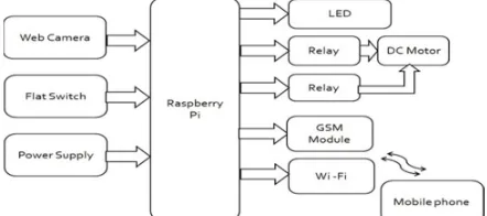
[image:2.612.195.416.599.697.2]To implement this project below block diagram is used. Figure 1 shows the web camera, flat Switch, relay circuit, LED, power supply and Wi-Fi module are connected to the Raspberry pi. DC motor is connected to relay circuit. If first relay circuit is on then DC motor will be rotated to open the gate and when second relay circuit is on then motor rotate anticlockwise to close the gate.
Raspberry pi is the main part of this project which is a minicomputer. In that OS can installed in SD card and program is run by using Python Idle. Python language is used for coding. Raspberry pi required a power supply of 3.3/5V. Web camera captures the images and that images send to the controller. The flat switch is input to the controller means after pressing that switch by the security guard the controller sends the SMS to the respective owner via GSM. LED used for indication of visitor and depends on that security guard can understand which flat switch should press. Relay circuit is used to decide when the motor rotate and the gate will be open and close. Wi-Fi module is used for sending the image on the android app of owner mobile.
III. FLOWCHART
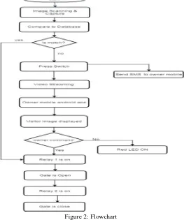
[image:3.612.176.449.201.516.2]In Raspberry pi, OS want to install. Then the first owner image details i.e. database of the owner of flats are store in SD card by Raspberry pi. Raspberry pi is a minicomputer for which we used Python programming language. Python is high-level language.
Figure 2: Flowchart
This system is always on. When any visitor has come in society then the image can be captured by the web camera will be recognized. The captured image is sent to Raspberry pi and it compares the captured images to previous stored owner's images. If image match with stored details then automatically gate will be open. Gate will be closed after entering of the owner. If no match found then blink the led in security guard cabin. Then security guard will press the flat switch of a respective flat where visitor wants to go. After that SMS will be sent to owner i.e. notification of visitor has come. Then the owner can see image on the android app, which is captured the image by camera send on owner mobile through Wi-Fi module.
IV. HARDWARE REQUIREMENT
A. Raspberry Pi
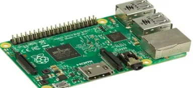
This is Raspberry Pi 2 model B is 6 times greater than processing capacity of previous models. This is second generation Raspberry Pi has an upgraded Broadcom BCM2836 processor, which is a powerful ARM Cortex-A7 based quad-core processor that runs at 900MHz. The board also features an increase in memory capacity to 1Gbyte [3]. There are a number of connectors used like fallowing:
B. Connectors
2) Video Output: HDMI (rev 1.3 & 1.4)
3) Audio Output: 3.5mm jack, HDMI
4) USB : 4 x USB 2.0 Connecto
5) GPIO Connector: 40-pin 2.54 mm (100 mils) expansion header: 2x20 strip Providing 27 GPIO pins as well as +3.3 V, +5 V and GND supply lines
6) Camera Connector: 15-pin MIPI Camera Serial Interface (CSI-2)
7) JTAG: Not populated
8) Display Connector: Display Serial Interface (DSI) 15-way flat flex cable
9) Memory Card Slot: connector with two data lanes and a clock lane Micro SDIO
C. Specification
1) Chip: Broadcom BCM2836 SoC
2) Core Architecture: Quad-core ARM Cortex-A7
3) CPU: 900 MHz
4) Memory: 1GB LPDDR2
5) Operating System: Boots from Micro SD card, running a version of the Linux operating system
6) Dimensions: 85 x 56 x 17mm
[image:4.612.219.411.311.399.2]7) Power: Micro USB socket 5V, 2A
Figure 3: Raspberry pi module
D. GSM
This is an SIMCOM 900 GSM/GPRS module is compatible with Quad band cell phone. Which does not a used only for internet access, this also used for communication purpose and send SMS, connect to the internet via GPRS through AT commands. It works on frequencies 850 MHz, 900 MHz, 1800 MHz and 1900 MHz. It is very compact in size and easy to use as a plug in GSM Modem. It operates on 5V /12Vpower supply.
E. Specification
1) Quad-Band GSM/GPRS 850/ 900/ 1800/ 1900 MHz
2) Built in RS232 Level Converter
3) Configurable baud rate(9600-115200)
4) Operation temperature: -40°C to +85 °C
5) Low power consumption: 1.0mA
6) Stub antenna and SMA connector
.
Figure 4: GSM module
F. Relay Circuit
[image:4.612.198.407.579.695.2]switch it is used for control circuit function as a coupling between the input and output circuit. We use n-p-n transistor for amplification of small current control. Diode is use for providing circuit security. LED is used for indication purposes. In that system 2 relay circuits are use one of them for gate opening in that green led will glow, and the second circuit for gate closing in that red led will glow.
Figure 5: Relay circuit
G. Wi-Fi Module
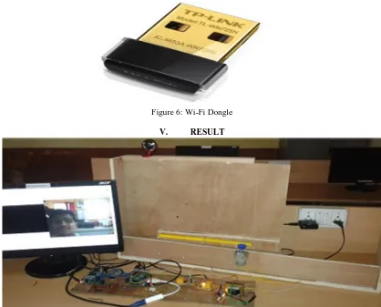
[image:5.612.95.513.360.697.2]Wi-Fi dongle (TL-WN725N) is connected through the USB port. It operates on 2.400-2.4835 GHz frequency with signaling rate of up to 11Mbps to 150Mbps and advanced technology used such as MIMO, Its works on an IEEE 802.11b, IEEE 802.11g IEEE 802.11n wireless standards. It has an internal antenna and also LED status for indication. This Wi-Fi module Compatible with WPA/WPA2 is secure connection, more secure than64/128 WEP encryptions. This tiny adapter works as a virtual wireless Access Point.
Figure 6: Wi-Fi Dongle
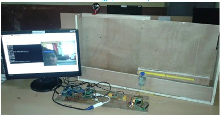
V. RESULT
Figure 8: Closing of gate after authorized person is entering into gate
VI. CONCLUSION
This system is more helpful in certain places like society, home, industries, lab and other automated systems etc. which is permitted only authorized entry and reduce the harm of unauthorized entry and give the safeguard. Evidence can be stored in the security department, if any problem occurred like robbery, stealing etc. If an unknown person has come then authorized person has authentication to allow the unknown person through a mobile application. If owner is outside for job or any other work then also notify which peoples are coming to meet him at their home.
REFERENCES
[1] Md. Nasimuzzaman Chowdhury , Md. Shiblee Nooman and Srijon Sarker, Access Control of Door and Home Security by Raspberry Pi Through Internet, International Journal of Scientific & Engineering Research, Volume 4, Issue 11,November-2013, ISSN 2229-5518