Design and Analysis of Floating Calipers for Two
Wheelers
Aman Singh1, Aadhar Bisht1 1
Department of Automotive Design Engineering, University of Petroleum and Energy Studies,
Abstract: The paper deals with the designing and modeling of light floating caliper for two wheelers without interfering with the performance. This would be done without affecting the manufacturing cost, which is a highly challenging point, at the selected position. A physical model is built to evaluate the FE-model with practical tests. The aim is to keep the manufacturing costs low, which is solved by using the same material and shape that follows the same machining steps. To make the caliper lighter it is necessary to remove material. To maintain the stiffness the material has to be used in a more efficient way.
Keywords: Floating Calipers, analysis, Braking System, Brake Calipers, Finite Element Method
I. INTRODUCTION
[image:2.612.208.403.426.562.2]The brakes are one of the most important safety systems in the vehicle. The vehicle uses brakes to bring the vehicle to a quick and safe stop regardless of weather conditions or topography. Driver exerts a force on brake pedal, which is further amplified by the lever ratio. The force exerted at master cylinder causes the displacement of fluid from master cylinder to the calipers. The backpressure at pistons causes the pistons to move against the disc causing frictional force to slow down the vehicle speed eventually. The clearance between the disc and the pads is maintained automatically by means of Viton seal ring between the piston and the cylinder. For optimal braking force, the diameter of the pistons should be enough that the force generated by the calipers should be more than the required braking force. In this research, we have considered TVS apache RTR 180 as a research object and its data to calculate the required dimensions.
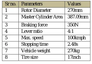
TABLE 1Analytical results for calculation of caliper Sr no. Parameters Values
1 Rotor Diameter 270mm
2 Master Cylinder Area 387.09mm
3 Braking force 350N
4 Lever ratio 4:1
5 Max. speed 100kmph
6 Stopping time 2.48s
7 Vehicle weight 270kg
8 Tire size 17inch
II. LITERATURE REVIEW
A Floating caliper is solidly mounted and the caliper itself within that bracket isn’t solidly mounted so they can move with respect to the disc, along a line parallel to the axis of rotation of the disc. A piston on the inner side of the calipers pushes the brake pads so as it to move the disc but the disc cant slide, the force pulls the sliding caliper with another brake pad unto the other side of the disc. The advantage of floating caliper is that it is lighter and economical than fixed calipers and it uses less part so its manufacturing is easy and it is more compact. Since it is lighter and cheaper, it is preferred for features like ABS and EBD.
III. CALIPER DESIGN
The design has been outlined by taking variables like dimensional limits (width, height, length and weight), operational limitations, and administrative issues, legally binding prerequisites, financial constraints and space availability as a need.
A. Caliper should be weight optimized.
D. A clearance is provided between the piston and the caliper bore in the absence of the seal grooves. E. The thickness of the material is calculated with certain factor of safety.
IV. DESIGN METHODOLOGY
The diameter of the piston was calculated for the required braking torque. The bleeding valve and port valve were fixed.
The whole design was performed on CATIA V5. The analysis was done to find the factor of safety.
A. Material Selection For Caliper Body
Aluminum 7075T6. It is the higher grade of aluminum, which gives us higher strength to sustain under loading. It is lightweight and due to its high strength to weight ratio and its high thermal conductivity
[image:3.612.187.429.284.405.2]It is preferred. Using this material is also advantageous in terms of bleeding as this material absorbs most of the heat so there are less chances of having air bubble and this will lead to minimum need of bleeding.
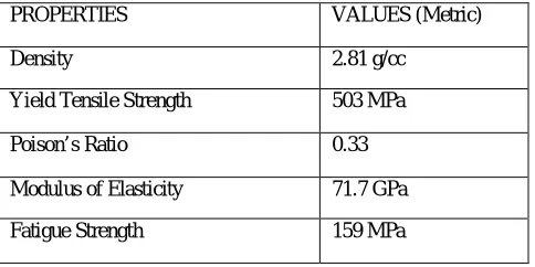
TABLE 2 Physical Properties of AL7075T6
PROPERTIES VALUES (Metric)
Density 2.81 g/cc
Yield Tensile Strength 503 MPa
Poison’s Ratio 0.33
Modulus of Elasticity 71.7 GPa
Fatigue Strength 159 MPa
B. Brake Pads
The distribution of the heat over the contact area between disc and pad during braking is investigated. An exact temperature distribution of the sliding contact surface involves a very complicated process and is dependent on many factors.
On microscopic level, so-called hot spots occur. This is due to the actual contact interface that is restricted to a few small areas at any particular time. These areas are distributed over the nominal contact area. Due to this limited contact interface, very high temperatures arise at these contact points: so-called hot spots arise. However, due to the small sizes, the amount of heat generated at each particular hot spot is rather low, despite the high temperatures that reached.
C. Material Selection For Brake Pads
Disc brake pads are composed of many different materials. The main structural materials are mixed together with different types of fillers and abrasives, and then bonded with resin or fiberglass to create the end result. The three types of brake pads are:
Organic- made from organic materials, which can last in extremely high temperatures such as glass, rubber, carbon, fiber, & Kevlar. They used to be made of asbestos before we knew how harmful it is.
Semi metallic- copper, brass, steel, graphite.
Ceramic- mostly ceramic fiber with some filler mixed in.
Common abrasive materials include metal oxides (aluminum/iron oxide) mineral fillers (quartz), synthetic silicates, & brass chips. The overall braking performance of the bike has to be very good to ensure safety, even when riding very fast. Therefore, material selected for braking is Ceramic brake pads. They are composed primarily by ceramic fibers with filling agents, but may also have small amounts of other materials, such as copper, as well. They dissipate heat very well, making them an excellent choice for two wheelers. Ceramic brake pads break down very slowly, which may or may not mean they need replacement less often, depending on how harshly they are used. Therefore, they are efficient too. The material is also incredibly lightweight, making it perfect for racing applications. However, the bikes that are driven hard can see braking improvements from ceramic pads.
D. Seal Groove Geometry
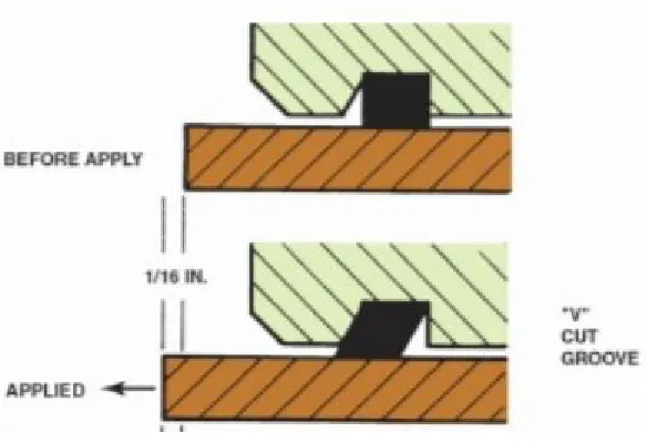
It is a sealing, which provides sealing to one direction only. Its function is to seal the piston bore and to act as a retraction seal to bring the piston back to its position after releasing the brakes. Certain parameters were considered while configuring the design of seal groove such as fluid displacement, piston retraction, piston sliding force, and brake drag. The biggest challenge was to increasing piston retraction, which conflicts with the displacement of piston travel. Therefore, the groove for O-ring is V-cut groove allowing for more retraction. When the brake pedal is released, the piston moves away from the rotor further, resulting in less friction between the brake disc and rotor when the brakes ae released.
Fig 1Seal Groove Geometry
E. Bleed Port
When the brakes are applied the heat transfer to the brake fluid which boils the fluid resulting in air bubbles formation. Which create an efficiency loss in the braking system. Overall reducing the performance of calipers. So, bleeding port as shown in fig. is provided at the top side of the caliper bore, since air always occupies the topmost point. To prevent a vacuum forming in the reservoir, there must be a breather hole in the cap. This is to ensure complete removal of air from the hydraulic system. It is tightened to the caliper body using a nut and bolt design so that it can easily be dismantled from the body.
[image:4.612.181.473.185.385.2]V. CALCULATIONS AND MATHEMATICAL EXPRESSIONS
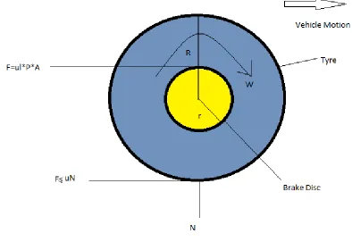
A. Braking force and Braking torque
For calculating the braking force, coefficient between tire and road is one of the key factor to be considered.
Fig 3Disc Brake-Braking Force and Braking Torque
From figure
Required braking force to stop the vehicle (for a two-wheeler) The vehicle of mass 270kg to stopped from 100 to 0 kmph in 2.48s So, from uniform motion equation, we get
v2=u2+2as a=11.20m/s2 Front to Rear weight ratio for a two-wheeler
At static condition is 50:50 Kerb weight =270*9.81=2648.7N For front axle Static load is Wf =2648.7*0.5=1324.35N For front axle dynamic load is Ff =Wf+ (a*W*H)/L
=1324.35+ (11.2*270*20.6)/52.2 =2517.72N
Torque produced on wheel is Tw =µ*Rt*Ff
=0.5*0.2159*2517.35 =271.78N-m
Now as the Torque at wheel is same as torque at disc Tw=Td
[image:5.612.101.495.156.436.2]F=271.78/0.1 =2717.78N
Fc=F/µd (µd=0.35 for rotor and brake pads) Fc=7765.085N
Fcl=Fc/2
Fcl=3882.54N (1)
Now the force applied by the driver is Fd=350N
Pedal Ratio- 4:1
So force exerted by driver is Ffr=1400N Pressure exerted by master cylinder
Pm=Ffr/Am Pm=1400/387.09 =3.616MPa
Pressure transmitted to caliper written as Clamping force generated by calipers is Fc=P.A
Fc =3.616*(π/4)*D2 (2)
From equations (1) & (2)
=3.616*(π/4)*D2=3882.54 D=36.97mm (3.7cm)
VI. RESULT AND DISCUSSIONS
A. Design Analysis
The caliper designed as monoblock with the cylinders on catia V5 and its dimensions are calculated. The modeling of caliper is done was done as per the calculated piston diameter and assembly constraints in the wheel rim.
Fig 4Cad Model of Caliper on catia V5
B. Finite Element Analysis
Finite Element Analysis FEA is the modeling of products and systems in a virtual environment, for the purpose of finding and solving potential (or existing) structural or performance issues. FEA is the practical application of the finite element method (FEM), which is used by engineers and scientist to mathematically model and numerically solve very complex structural, fluid, and multiphasic problems.
[image:6.612.168.446.424.599.2]Fig 5Static Analysis
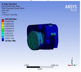
2) Strain Analysis: Strain analysis was done to calculate the maximum stress developed in caliper using modulus of elasticity.
Fig 6Strain Analysis
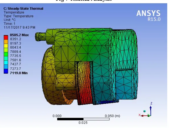
[image:7.612.182.433.87.335.2] [image:7.612.167.449.403.653.2]Fig 7Thermal Analysis
[image:8.612.164.451.85.302.2]The stress results show that factor of safety for the designed model is within limits Thermal stresses were taken into consideration. The parameters decided could help in further lowering the manufacturing cost and weight.
TABLE 3 Deformation and Stress Analysis
Δmax mm 0.04409
σmax (MPa) 75.71
FOS 4
VII. CONCLUSION
The caliper is designed taking in account its reliability, lifecycle, service, performance and weight. The caliper designed with a single piston keeping in mind the space constraints and improving performance. This caliper to be used in front brake systems of motorcycles to get its maximum efficiency.
REFERENCES
[1] https://parts.olathetoyota.com/what-are-brake-pads-made-of
[2] http://asm.matweb.com/search/SpecificMaterial.asp?bassnum=MA7075T6 [3] https://textar-professional.com/floating-caliper-brake/
[4] Willian F, Milliken and Douglas L, Milliken, Race car Vehicle Dynamics [5] Paul S. Gritt, Brake Systems 101 presented
[6] Forsman, A. and Bladh, M.Low weight brake caliper, Master of Science Thesis, KTH Industrial Engineering and Management013 , MMK 2009:10 [7] Rafael Blumberg, Nicolino Foschini Neto. Design of high performance automotive brake caliper using ANSYS
[8] fred puhn, Brake Handbook
[9] Ali Belhocine,Mostefa Bouchetara, Structural and thermal analysis of automotive disc brake rotor, Archive Of Mechanical Engineering VOL. LXI 2014 Number 1
[10] Mahmood Hasan Dakhil, A. K. Rai, P. Ravinder Reddy & Ahmed Abdulhussein Jabbar Design And Structural Analysis Of Disc Brake In Automobiles
IX. NOMENCLATURE
R Effective rolling radius of tire R Radius of disc
F Braking force between tire and road surface
F1 Tangential braking force between disc and brake pads Fc Clamping force
u Coefficient of friction between tire and road surface u1 Coefficient of friction between disc and brake pads P Hydraulic brake line pressure
A Area of calipers
N Normal reaction on wheel under unladen condition Wf Static load at front
Ff Dynamic load at front
µ Coefficient of friction between tire and road Rt Effective radius of wheel
F Frictional force Fc Clamp force
Pc,Pm, P Pressure in hydraulic line