N A N O E X P R E S S
Open Access
Synthesis and Electrospraying of Nanoscale
MOF (Metal Organic Framework) for
High-Performance CO
2
Adsorption Membrane
Wahiduzzaman
1, Kelsey Allmond
2, John Stone
2, Spencer Harp
1and Khan Mujibur
1*Abstract
We report the sonochemical synthesis of MOF (metal organic framework) nanoparticles of 30–200 nm in size and electrospraying of those particles on electrospun nanofibers to process a MOF-attached nanofibrous membrane. This membrane displayed significant selectivity towards CO2and capacity of adsorbing with 4000–5000 ppm difference from a mixed gas flow of 1% CO2and 99% N2. Applying ultrasonic waves during the MOF synthesis offered rapid dispersion and formation of crystalline MOF nanoparticles in room temperature. The MOF
nanoparticles of 100–200 nm in size displayed higher surface area and adsorption capacity comparing to that of 30–60 nm in size. Nanofibrous membrane was produced by electrospinning of MOF blended PAN solution followed by electrospraying of additional MOF nanoparticles. This yielded uniform MOF deposition on nanofibers, occurred due to electrostatic attraction between highly charged nanoparticles and conductive nanofibers. A test bench for real-time CO2adsorption at room temperature was built with non-dispersive Infrared (NDIR) CO2sensors. Comparative tests were performed on the membrane to investigate its enhanced adsorption capacity. Three layers of the as-produced membranes displayed CO2adsorption for approximately 2 h. Thermogravimetric analysis (TGA) of the membrane showed the thermal stability of the MOF and PAN up to 290 and 425 °C, respectively.
Keywords:MOF, PAN, Electrospinning, Nanofibers, Electrospraying, CO2adsorption
Background
The continuing demand for energy around the world is a primary reason for utilizing available resources such as fossil fuels, coals etc. at extremely high rates. As a result, large amounts of hazardous gases are released into the environment which has become a major global concern for the environmentalists [1]. Carbon dioxide, a leading proponent of Greenhouse effect is the matter of concern especially due to its rapid increase in the atmosphere. The recently reported CO2concentration in the
atmos-phere has been found as 404 ppm with an alarming in-creasing rate of 2.9 ppm/year [2].
In the world of nanotechnology, a significant amount of research has been conducted over the last few years to produce an effective methodology to adsorb CO2gas.
Mishra and Ramaprabhu suggested a system of magnetite
multi-walled carbon nanotubes which were prepared by a catalytic chemical vapor deposition method followed by purification and functionalization. The functional results proved that this composite material system worked fine in absorbing CO2gas under high pressure and temperature
[3]. Activated carbons (ACs) and zeolite-based molecular sieves have shown good performance in high CO2
adsorp-tion capacities [4]. Electric swing adsorpadsorp-tion system also drew further attention. In this process, a cycle of seven steps (feed, rinse with hot CO2-rich stream, internal rinse,
electrification, depressurization, and purge) ensured CO2
absorption procedure from flues gases of natural gas power station [5]. Using Grand Canonical Monte Carlo simulations for modeling, effective absorption of hydrogen-methane mixtures in idealized single-walled nanotubes had been observed. Performance analysis of these kinds of nanotubes was done in different pressure, along with room temperature [6]. In case of post-combustion gas capturing, properties, and qualities of nanomaterials gave a viewpoint on interesting and highly * Correspondence:[email protected]
1Department of Mechanical Engineering, Georgia Southern University,
Statesboro, GA 30458, USA
Full list of author information is available at the end of the article
effective absorption capacity for CO2[7]. Nanomaterials,
therefore, are considered to be highly potential in CO2
capturing due to their large surface areas and adjustable properties. Recently, solvent stripping by ammonia is known as an effective way to absorb high amount of CO2
[8]. Several other different kinds of nanomaterials includ-ing nanocrystalline NaY zeolite, ZnO, MgO nanoparticles as well as mixed phase aluminum nanowhiskers have been investigated for adsorption analysis [9]. Nanocrystalline zeolites possess high external surface area and active sites present on the external surface to adsorb a significant amount of CO2 gas [10]. The nano-adsorption materials
both have pros and cons, as discussed by Wang et al. [11]. CaO nanopods comparatively have higher selectivity to-wards CO2, eventually displayed higher adsorption capacity.
Carbon nanotubes (CNT) functionalized with nanofibers have higher surface area but less selective to CO2.
Metal organic frameworks (MOF) are crystalline porous materials constructed by metal ions and organic ligands. Considered to be a breakthrough material for gas adsorp-tion purpose, MOFs possess three dimensional crystalline structures formed by the coordination bond between metal based salts and organic ligands. Properly synthe-sized and tuned MOF particles exhibit high surface area and porosity, making them able to act as a gas storage tank. It offers unchanged and optimized gas uptake cap-acity. Molecular level tuning and functionalization of the MOF particles are required to improve the adsorption capacity and selectivity towards certain gas [12]. They pos-sess crystallographically well-defined robust 3D structures with extremely large surface areas compared to volume. CO2 binding on adsorption sites can also be further
en-hanced by incorporation of unsaturated metal centers, metal doping, and chemical functionalization. Other tun-able properties such as low energy regeneration, stability in the presence of moisture, and various operating condi-tions have shown much promise in the utilization of MOFs as physisorbent or chemisorbent materials on an industrial scale [13]. When the MOF crystals started to form inside the precursor solution, small micro- and nano-pores have been formed on the crystal surface. When the solvents are evaporated, these pores have be-come open and acted as pathways of gas capturing access [14]. Synthesis of MOF has usually been done by sol-vothermal process which consists of mixing the specific metal salt and organic linker for a certain period of time and post-processing afterwards to attain the desired microcrystalline porous structures [15]. Sonochemical method has also been reported for MOF synthesis. The method of generating ultrasonic waves through the pre-cursors offers a rapid and homogeneous nucleation of the particles, forming MOF [16]. This method is proven to be effective to achieve reduced particle size with well-defined crystallography [17]. SEM, TGA, XRD, and Raman
Spectroscopy are some of the well-known morphological and characteristic analysis to investigate the crystallinity and CO2 adsorption performance of MOF [18]. As high
temperature synthesis of MOF had found to produce un-desirable by-products such as metal oxides, room temperature synthesis has become a considerable solution for that [19]. Surface and size control of MOFs have also drawn much attention for research endeavors. The initially synthesized MOF crystals size was mostly confined to big micron size particles. Using ultrasonic waves, Tehrani et al. produced nanorod-like shaped HKUST-1 crystals [20]. Using microwave radiation has also proved to be useful to produce nano MOFs. Comparative analysis of Ni and Mg-based MOFs between typical solvothermal and microwave approach displayed exceptional reduction in MOF size and shape [21]. Klinowski et.al also adopted microwave synthesis but instead of radiation, they opted for micro-wave heating which also allowed short reaction times, fast kinetics of crystal nucleation and growth, and high yields of desirable products which can be isolated with few or no secondary products [22]. Several other unique approach have been undertaken to synthesize nano size MOF crys-tals. Sanchez et al. had come up with spray-drying meth-odology to dissemble a HKUST-1 MOF encrust into nano-MOF crystals [23]. This spray-drying strategy en-ables the construction of multi-component MOF super-structures and the encapsulation of guest species within these superstructures.
Electrospinning is a versatile and most widely used and preferred process to produce sub-micron and nanoscale polymeric fibers. A polymer solution of sufficient viscosity and moderately high molecular weight is drawn from a spinneret under the influence of a high voltage electric field. The influence of electrostatic force and surface ten-sion on the solution droplet helps it stretch into continu-ously formed nanoscale fibers. During the spinning, the solvent solution gets evaporated, and solid electrospun fi-bers are collected in a collector placed underneath [24]. Free-standing MOF membrane can be produced on elec-trospun fibrous mats for gas adsorption purpose. Different types of MOF crystals such as HKUST-1, ZIF-8, and MIL-101 have been used to fabricate the membrane [25]. How-ever, most MOF particles were seen encapsulated in the fi-bers, thus made it inefficient for CO2 adsorption.
MOF particles have been found difficult because of the unavailability of finding a way of attaching MOF particles on the fiber surface. Centrone et al. performed in situ microwave irradiation to grow MOF particles into the polymer surfaces [28]. The particles were seen mostly ag-glomerated or discretely dispersed on the fiber surface, making the substrate almost invisible. With the formation of small MOF nanoparticles attached to the electrospun fiber substrates, it is possible to increase the gas uptake capacity of the membrane. Using coordination modulation method, size of MOF particles was reduced to nanoscale [29]. Atomic layer deposition (ALD) and anionic treat-ment of precursor fibers have made it possible to attach large amount of nano MOF particles on the substrate fi-bers [30, 31]. However, ALD process is costly and anionic treatment is not suitable for strong polymer-based fibers such as PAN. Therefore, further emphasis should be given on generating an applicable and cost-effective method of fabricating nanofibrous CO2 adsorption membrane. Our
previous approach to produce a MOF-loaded adsorption membrane consists of electrospun PAN (polyacrylonitrile) membrane loaded with MOF particles of 3–6 μm in size [32]. HKUST-1 was selected as MOF because of its excellent adsorption performance and compatibility with PAN. This is a Cu-based MOF (empirical formula C18H6Cu3O12), typically known to have octahedral
crystal-line structure. The formation of the HKUST-1 is highly in-fluenced by the precursors, solvents, synthesis method, and post-processing. Cu(NO3)2was chosen as the primary
precursor because of its stronger characteristic peaks found in the XRD patterns over CuCl2 and Cu(CH
3-COOH)2[33]. In this work, a new approach of
conjugat-ing electrosprayed HKUST-1 nanoparticles on electrospun nanofibers is reported in order to produce a nanofibrous membrane for enhanced CO2adsorption performance.
Experimental Methods Synthesis of MOF Nanoparticles
HKUST-1 was selected as the MOF to be conjugated with the electrospun nanofibers to produce the adsorption membrane. Sonochemical approach of MOF synthesis was carried out by mixing 2.55 gm of Cu(NO3)2.3H2O salt and
0.45 gm of Trimesic acid (1,3,5-benzenetricarboxylic acid) in a 200-mL solvent mixture of DMF, ethanol, and DI water (1:1:1) with an addition of 1 mL of TEA (Triethyla-mine) as deprotonating agent. The mixture was sonicated in room temperature for different time period of 30, 60, and 120 min. The sonication yielded blue HKUST-1 crys-tals during the synthesis which were later extracted and washed with the mother liquor three times via centrifu-ging. The obtained MOF crystals were then dried in a vac-uum oven at 120 °C for 18 h to ensure complete evaporation of the remaining solvents and activation.
Electrospinning of MOF Hybridized Nanofibers
In a 33 mL solution of DMF, 0.45gm (15 wt% of PAN) of HKUST-1 was added and started mixing using a sheer mixer at 70 °C. An amount of 3 gm of PAN was added to this solution slowly. The mixing was carried out for 3 h, eventually made a blue precursor solution of PAN with MOF embedded inside. Two syringes of 6 mL each of the prepared solution were placed into the NF-500 electrospinning unit. Multi-jet spinneret was used during the electrospinning process. The flow rate applied was 1.2–1.4 ml/h and voltage was 24 to 26 KV. Using multi-jet spinneret, it made possible to run the spinning of the two solutions at the same time. This produced a con-tinuous streamline of nanofibers drawn from both of the needles which were collected on a cylindrical porous canister model as shown in Fig. 1. The collector was kept rotating at a speed of 120–140 rpm, and the dis-tance between the syringe needles and the collector was kept in between 150 and 170 mm. Relative humidity was kept at 30–40% because of PAN’s sensitivity to water or moisture. This eventually produced MOF hybridized
non-woven PAN nanofibrous membrane, wrapped
around the canister model. The color of the membrane is bluish-white, contrary to plain white color of neat PAN fiber mat. The fiber canister was then dried in a vacuum oven at 50 °C for 3 h.
Electrospraying of HKUST-1 Nanoparticles on Nanofibrous Membrane
Electrospraying is a method of liquid atomization by means of electrical forces. The liquid during electro-spraying flows out of a capillary nozzle, maintained at an extremely high voltage. The particle formation is forced by the electric field to be dispersed into fine droplets. In this work, 1 wt% of the previously synthesized HKUST-1 nanoparticles was dispersed in ethanol by sonicating for 15 min, forming a stable MOF suspension. Using multi-jet spinneret, the solution was then electrosprayed at an extremely high voltage of 40–45 KV. In order to achieve that high voltage in the electrospinning unit, the collector-needle distance had to be maintained at 150 mm or above. A high flow rate of 3.5–4 ml/h was implied during the electrospraying process. The process was carried on for 5 h. This approach was proved to be effective for MOF conjugation, eventually led to a uni-form blue colored membrane. The membrane was kept in vacuum oven and dried at 45 °C for 2 h to influence rapid crystallization of the MOF particles.
CO2Adsorption Test
A test setup was built for real-time CO2 adsorption at
placed into the chamber and tightly sealed with 3D printed sealing caps. Two NDIR (non-dispersive infra-red) CO2 sensors, purchased from CO2 meter, were
placed at the inlet and outlet ports. The sensors came with a dust filter and a hydrophobic filter. Sample gas was drawn into the sensors by a motor driven pump. The sensors read the concentration of CO2in the
sam-ple gas in ppm (parts per million). Real-time data of CO2concentration can be plotted from the sensors by
using GASLAB software. The accuracy of the sensors is roughly ±70 ppm [34]. They were calibrated at zero point with a calibration gas of known gas concentration. It takes 50 s to stabilize and get fully diffused by the cali-bration gas. A gas tank contains 1% CO2 and 99% N2
was used for gas inflow.
The adsorption tests were performed in room
temperature. The total volume of the test chamber was calculated as 1278.2 cm3. Methodology of the test consists of fill the gas chamber for a certain period of time, letting the filter membrane to adsorb CO2and refill it again after
releasing the previous gas inflow. Any disturbance or vi-bration, or movement of the test setup was not required because of causing fluctuation in the CO2reading.
Elem-entary adsorption can be detected by the real-time plot difference between the CO2values at inlet and outlet.
Results and Discussion HKUST-1 Nanoparticles
The sonochemical synthesis of HKUST-1 produced sig-nificant size reduction in MOF particles thus achieving
Fig. 1Electrospinning of HKUST-1 hybridized PAN nanofibers
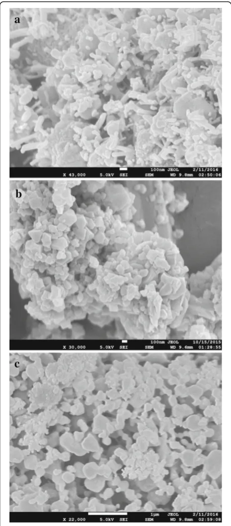
[image:4.595.61.538.86.319.2] [image:4.595.60.540.553.714.2]higher surface area and increased gas adsorption per-formance. The ultrasonic waves during sonication caused fast dispersion and disintegration of precursor materials, which led to a homogenous reaction and for-mation of smaller MOF particles at room temperature within a short period of time. Using TEA as nucleation agent during synthesis influenced the rapid deproton-ation of the organic linker, resulting in homogenous nu-cleation and reduction of the particle size [35]. The obtained crystals were found to be in nanoscale after washing and post-treatment. A 2 h of sonication eventu-ally produced HKUST-1 crystals of 30–60 nm (Fig. 3a). But an hour of sonication produced fine octahedral crys-tals of 100–200 nm (Fig. 3b). Figure 3c showed nano-crystals of 400–600 nm synthesized from a sonication period of only 30 min. Table 1 shows the effect of sonic-ation time period on the nanocrystals size distribution.
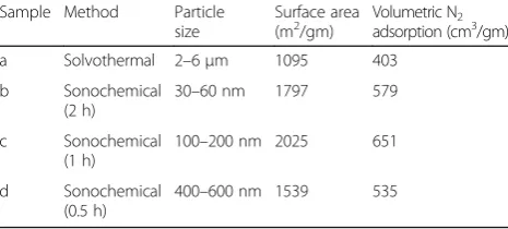
On the one hand, conventional solvothermal method is known to yield large micron-size MOF crystals. Sol-vothermal synthesis of HKUST-1 particles (2–6 μm) had also been reported in our previous work [32], which has taken into account in here as well for a comparative BET analysis between that and the newly synthesized particles by sonication. Table 2 provides the data of sur-face area and maximum volumetric N2adsorption of the
HKUST-1 samples, and Fig. 4 shows the adsorption iso-therms of those samples. The isotherm for HKUST-1 sample of an hour of controlled sonication (MOF-c) showed the largest increasing pattern followed by MOF-b and MOF-d. The smallest pattern was oMOF-bserved for MOF-a, synthesized by solvothermal method. From Table 2, it was also clearly seen that the sonochemical samples displayed higher surface areas with notable in-crease in N2 uptake capacity comparing to that of
sol-vothermal method. The highest surface area (2025 m2/gm) was achieved by MOF-c which also displayed typical octa-hedral crystalline structure of HKUST-1. On the other hand, solvothermal approach displayed HKUST-1 particles of significantly lower surface area of 1095 m2/gm which oc-curred due to the prolonged heating of the precursors at high temperature. The crystallization of MOF in solvother-mal method carried on as long as the particles remained in the solution, thus continued their surface augmentation. In addition, there were unwanted by-products such as Cu2O
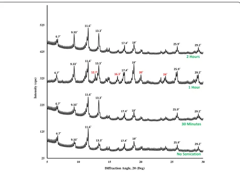
which remained in the pores of the structure. It was also observed from the BET tests that, although increasing son-ication time produced smaller particles, this also subse-quently reduced the surface area and the volumetric capacity of the MOF nanoparticles when sonication time increased from 1 to 2 h. The XRD diffraction patterns of different HKUST-1 samples with different sonication time are shown in Fig. 5. Characteristic peaks of HKUST-1 at 6.7°, 9.33°, 11.6°, 13.3°, 17.4°, and 19° were found, which ap-peared to be similar with the work reported by Wang et.al
and Biemmia et.al [36, 37]. Samples prepared by using son-ication displayed sharp characteristic peaks compared to the samples with no sonication. It is also observed that, the intensity of the peak at 9.33° has increased with increased sonication time. More importantly, it has been found that the XRD pattern of HKUST-1, sonicated for an hour,
a
b
c
[image:5.595.305.538.87.618.2]showed the well-defined characteristic peaks at 12.7°, 16.3°, 20°, and 24°, which is not present with the other categories of samples. We believe the samples with 1 h sonication have presence of more crystalline mixed phases when com-pared to the other categories of samples.
Electrospinning of HKUST-1 Blended PAN Nanofibers Electrospinning of PAN nanofibers displayed non-woven nanofibrous white outlook (Fig. 1). When HKUST-1 par-ticles were included in the PAN precursor solution, the nanofibers appeared to be bluish-white. The inclusion can be found either as impregnated inside the fiber or non-uniformly distributed along the fiber surface. From SEM image of neat PAN nanofibers in Fig. 6a, well-smoothed fibers can be seen without any beads or parti-cles seen anywhere. On the other hand, Fig. 6b shows impregnation of MOF material found inside the spun fiber. Figure 6c shows a general view of the MOF-loaded nanofibers, showing presence of particle distributed along the fiber surface. The presence of MOF parti-cles can even be increased in the PAN fibers, but higher loading of MOF eventually affected the elec-trospinning process. Instead of having continuous fi-bers, undesirable flakes and droplets were found because of the presence of larger MOF crystals. The impregnated and dispersed MOF particles in the fi-bers are for creating seed layers and contact points for additional MOF inclusion. Nevertheless, the as-produced fiber mat would not be proven effective for gas adsorption purpose because of low amount of MOF particles and lower total surface area. Therefore, an additional approach of electropsraying HKUST-1 nanoparticles was undertaken.
Electrospraying of HKUST-1 Nanoparticles on the PAN Membrane
The rapid sonochemical synthesis of nanoscale HKUST-1 paved the way of formulating new methodology conju-gating MOFs with nanofibrous membrane. The nano HKUST-1 particles showed a comparatively more stable suspension in ethanol. Electrospraying of the MOF parti-cles at the extremely high voltage with faster flow rate made the particles plausible to be accumulated on the previously electrospun nanofibers with strong attach-ment. The MOF particles during electrospraying became highly charged, eventually deposited on the conductive PAN fibers with strong attachment. This attachment was due to the strong electrostatic attraction between the charged MOF particles and conductive PAN nanofibers. The higher flow rate of electrospraying also influenced the MOF deposition. Figure 7a showed the SEM image of the MOF-loaded nanofibers where nano HKUST-1 particles are seen distinctively attached to individual fi-bers, appeared as a necklace-like structure. The typical crystal structure of HKUST-1 was also evident in those conjugated HKUST-1 nanoparticles. Figure 7b showed a substantial amount of MOF conjugated with the fibers, achieved by a three-hour duration of continuous electrospraying.
BET Analysis of the Adsorption Membrane
The sonochemically synthesized nano-MOF electro-sprayed fiber membrane showed an increasing surface
area of 1217 m2/gm and a pore volume of 0.53–
0.56 cm3/gm. The maximum N2 adsorption capacity of
the membrane was 412.23 cm3/gm. The values are sig-nificantly larger than the fiber membrane reportedly produced using the MOF particles synthesized by sol-vothermal method [32]. A comparative BET analysis be-tween the two differently produced membranes is given in Fig. 8.
Real-time CO2Adsorption Test
The purpose of the breakthrough CO2 adsorption
ex-periment was to determine the real-time gas adsorption performance of the fabricated membrane. Leakage tests have been performed to ensure no leaks in the enclosed setup. The flow rate of the gas inflow to the cylindrical chamber was 94 cm3/s for 13 s, and the working pres-sure was kept at 48.26 kPa. Each cycle of breakthrough testing contained entrapment of mixed gas in the gas chamber and allowing the fiber membrane placed inside to adsorb it. First test was run on neat PAN nanofiber mat for over 10 min. It was observed that no adsorption took place inside the test chamber as both the inlet and outlet sensors gave the data relates to 1% CO2(Fig. 9).
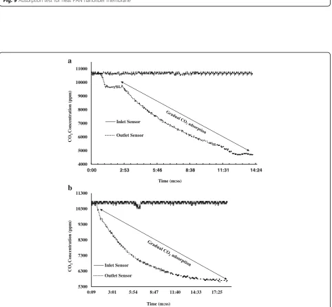
[image:6.595.55.291.110.175.2]In Fig. 10a, the first run of adsorption test for the elec-tropsrayed fiber membrane is shown. The gradual Table 2Particle size and surface area of the HKUST-1 samples
Sample Method Particle size
Surface area (m2/gm)
Volumetric N2
adsorption (cm3/gm)
a Solvothermal 2–6μm 1095 403
b Sonochemical (2 h)
30–60 nm 1797 579
c Sonochemical (1 h)
100–200 nm 2025 651
d Sonochemical (0.5 h)
[image:6.595.57.290.627.732.2]400–600 nm 1539 535
Table 1Experimental data of HKUST-1 synthesis or different sonication time
Sonication time (hour)
Addition of TEA (mL)
Post-heating time (hour)
Yield (%) Particle size (nm)
2 1 12 79 30–60
1 1 15 64 100–200
degradation at the outlet sensor reading started display-ing after 35 s of initialization. The test was run for al-most 10 min with a total difference of 6100 ppm between the inlet and outlet sensor reading. The per-centage of reduction of CO2 was 35.38%. Test 2 was
carried on for the electrosprayed membrane for a longer time to observe the gas uptake capacity of the product. A maximum gas loading at the chamber at 118 cm3/s rate was undertaken for 30 s. The pressure was in-creased to 55.15 kPa. The declining pattern at the outlet 200
250 300 350 400 450 500 550 600 650
0 . 0 5 2 0 . 1 0 2 0 . 1 5 2 0 . 2 0 2 0 . 2 5 2
MOF-d
MOF-c
MOF-b
MOF-a
Relative Pressure (P/P0)
V
o
lumetric
Ad
sorp
tion
(cm
3/gm)
Fig. 4Adsorption isotherms of the HKUST-1 samples
25 125 225 325 425 525
5 10 15 20 25 30
In
tens
ity (cps
)
Diffraction Angle, 2 (Deg)
[image:7.595.58.541.87.282.2] [image:7.595.61.538.375.717.2]sensor was noticed after 25 s of initialization. After 22 min, the gas concentration showed a total difference of 5200 ppm, showed in Fig. 10b. The percentage of re-duction of CO2 was 28.65%. The total adsorption time
for the new membrane after a few more similar experi-ments was found to be almost 80 min, before the
membrane led into saturation with filled gas. CO2
mole-cules are known to have a larger quadrupolar moment and smaller kinetic diameter comparing to N2. This
re-sults in strong interaction between CO2 and the open
metal sites of MOF with higher binding energy [38].
a
b
c
Fig. 6SEM images of (a) neat PAN nanofibers, (b) HKUST-1 impregnated nanofibers, and (c) discrete HKUST-1 particles around the fiber membrane
a
b
Fig. 7SEM images of (a) MOF electrosprayed functional nano-fibers and (b) enhanced nano-MOF attachment on the nanofibers
0 50 100 150 200 250 300 350 400 450
0.05 0.1 0.15 0.2 0.25 0.3
V
olum
etric Adsorption
(c
m
3/gm
)
Relative Pressure (P/P0)
(a)
(b)
[image:8.595.308.538.87.441.2] [image:8.595.56.288.89.611.2] [image:8.595.304.539.551.682.2]10100 10250 10400 10550 10700 10850 11000
0:00 2:53 5:46 8:38 11:31 14:24
CO
2
Con
cen
tration
(p
p
m
)
Time (m:ss)
Inlet Sensor
Fig. 9Adsorption test for neat PAN nanofiber membrane
4000 5000 6000 7000 8000 9000 10000 11000
0:00 2:53 5:46 8:38 11:31 14:24
CO
2
Con
cen
tration
(p
p
m
)
Time (m:ss) Inlet Sensor
Outlet Sensor
5300 6300 7300 8300 9300 10300 11300
0:09 3:01 5:54 8:47 11:40 14:33 17:25
CO
2
Con
cen
tration
(p
p
m
)
Time (m:ss) Inlet Sensor
Outlet Sensor
a
[image:9.595.56.542.89.266.2]b
[image:9.595.58.541.268.714.2]Moreover, the crystal structure of HKUST-1 has a sub-stantial selectivity factor of 7:1 towards CO2over N2in
room temperature at around 35 kPa [39]. This also cor-roborates the CO2 selectivity and superior adsorption
performance of HKUST-1.
An open channel test was performed as well for the electrosprayed fiber membrane. For longer time of ad-sorption, a layer-by-layer fabrication of the MOF-loaded fiber membrane was undertaken. There were, overall, three layers of nanofibrous membrane were produced on a single canister model. The thick membrane was then used for the adsorption test in an open channel, operat-ing at a low pressure of 1–2 psi and a reduced flow rate of 5–6 ft3/h. As found from Fig. 11, the open channel test displayed a different pattern of CO2 reading in the
outlet sensor. The ppm reading in the outlet followed a decreasing trend with several peaks. This pattern was
found due to the continuous flow of gas which allowed the fiber membrane less time and contact sites to cap-ture and store CO2. The adsorption took place for a
sig-nificantly longer period of almost 102 min, gradually lowering the ppm level to 6500 ppm before the mem-brane became saturated. This testing approach signifies the increasing adsorption efficacy and prospective use-fulness of the fiber membrane at different open gas out-let sources.
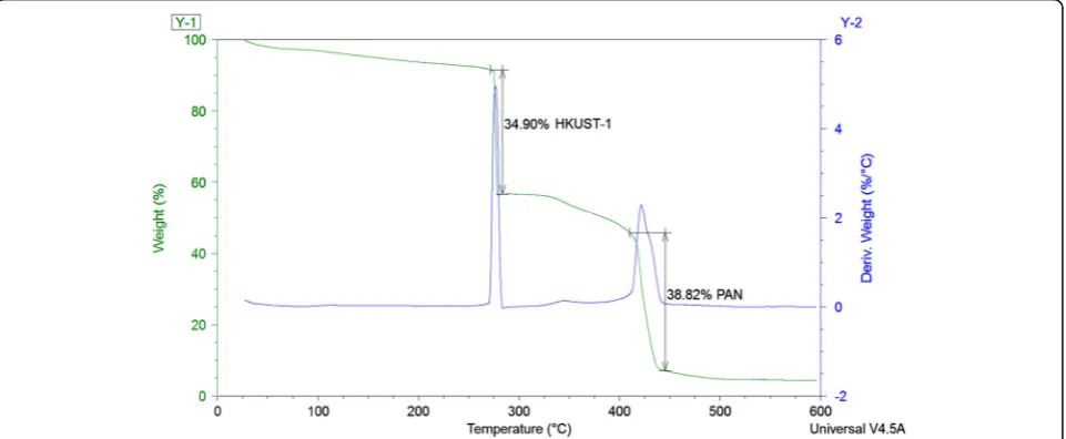
Thermogravimetic Analysis (TGA) of the Membrane Thermogravimetric analysis (TGA) was performed on the HKUST-1/PAN membrane to determine the thermal stability and elemental analysis. The TGA was carried on up to 650 °C at a heat rate of 5 °C/min. The fiber mem-brane is assumed to be functional in high temperature and rough environment. From Fig. 12, it was observed 6500
7200 7900 8600 9300 10000 10700 11400
4:19 11:31 18:43 25:55 33:07 40:19 47:31 54:43 61:55
CO
2
Con
cen
tration
(p
p
m
)
Time (m:ss) Inlet Sensor
[image:10.595.61.540.87.281.2]Outlet Sensor
Fig. 11CO2 adsorption data for open channel gas flow
[image:10.595.59.540.516.714.2]that the sample had a gradual degradation of element degradation. Two sharp peaks of 35 and 39 wt% loss of material were observed in the temperature range of 270–290 °C and 400–430 °C, respectively. The first peak signified the weight loss of HKUST-1 nanoparticles which was found to be similar with the work of Wang et al. [40]. The second peak verified the thermal stability of electrospun PAN nanofibers for a higher temperature range, similar to what was reported by Chauque et.al [41]. It was also observed that, the thermal decompos-ition of the previously reported micron-scale MOFs oc-curred from 150–220°, which signified the increased thermal stability for the nanoscale MOF particles. The overall thermal stability of the nano-MOF-loaded mem-brane therefore, can be functional at harsh environment.
Conclusion
In this work, HKUST-1 MOFs were synthesized at room temperature by sonochemical method where, instead of typical solvothermal heating, the precursor solution was sonicated for a certain period of time. The resultant product was blue HKUST-1 nanoscale crystals of 30– 200 nm. The nanocrystals were washed multiple times and heated at 100–120 °C for 18 h to ensure activation of the product for adsorption. The smaller MOFs offered substantially larger BET surface area, up to 2025 m2/gm. Electrospinning of HKUST-1 blended PAN precursor produced a nanofibrous membrane which was used as substrates for additional MOF loading. The nanofibers were contained with MOF particles, showing small de-gree of impregnation and dispersion in the nanofibers. The membrane was used as substrate for additional MOF inclusion. By applying electrospraying of the nano-MOF particles on the fiber substrates, a novel functional fiber membrane was produced. SEM images of the fiber samples showed distinctive attachment of MOF nano-particles with the fiber body, appeared to be necklace-like structure. By electrospraying for a longer time, the amount of MOF attached to the fiber body was signifi-cantly increased. The BET analysis of this membrane dis-played a surface area of 1217 m2/gm and maximum N2
adsorption of 412 cm3/gm. The nanofibrous membranes were then placed into a test bench for testing the ad-sorption capacity. A mixed gas tank containing 1% CO2
was used for the experiment. Two infrared CO2sensors
were connected at the inlet and outlet of the test bench to determine the difference of CO2 concentration in
ppm. Test 1 showed a difference of 6100 ppm within a timeframe of 10 min, and test 2 showed a difference of 5200 ppm after being ran for 22 min. The electrosprayed
membrane showed notably enhanced CO2 capturing
performance, operated for a longer time period of total 80 min. Three layers of electrosprayed MOF fiber mem-brane were then carried out. The memmem-brane was
undertaken for an open gas flow channel at a very low pressure. The adsorption in the membrane took place for almost 102 min before getting saturated. The outlet sensor plot displayed a slowly decreasing trend with sev-eral peaks. X-ray diffraction analysis of the MOF nano-particles showed characteristic HKUST-1 pattern with specific peaks. From the TGA analysis, it was certain that the fiber membranes have good thermal stability with a decomposing temperature at 270 °C.
Abbreviations
BET:Brunauer–Emmett–Teller; MOF: Metal organic framework; PAN: Polyacrylonitrile; SEM: Scanning electron microscopy; TGA: Thermogravimetric analysis; XRD: X-ray diffraction
Acknowledgements
The authors would like to acknowledge the support through NSF MRI grant (DMR-1337545), the Sustainability Fee Grant by the Center for Sustainability of Georgia Southern University, the Department of Mechanical Engineering, and Department of Chemistry of Georgia Southern University. The authors would also like to express their sincere gratitude to Dr. Rafael Quirino, Dr. Hao Chen, Dr. Nathan Takas, and Dr. Don McLemore for their assistance on using different characterization instruments.
Funding
The work was partially supported by FY2015 Sustainability Fee Grant from Center for Sustainability, Georgia Southern University. The graduate students were supported through Graduate Assistantship from Department of Mechanical Engineering and Department of Chemistry at Georgia Southern University.
Authors’Contributions
MK (lead and corresponding author): Dr. Khan from the Mechanical Engineering Department of Georgia Southern University was the PI of this project and received the Sustainability Fee grant for conducting the research. He is the major professor who has brought the idea and explored the necessary science and engineering of this project. He led the way of organizing all the aspects of the research, monitored and supervised the tasks related to the project. He has supervised the preparation of this manuscript, made all the necessary changes and contributed as the lead author. W (first author): Wahiduzzaman was the graduate student of Dr. Mujibur Khan in this research project. He conducted the necessary background literature research, did most of the experiments and
characterizing tests, optimized the processing parameters of electrospinning, electrospraying, synthesis of MOF particles, and performed the adsorption tests of the prepared nano-membrane filter canister. He has prepared this manuscript under the supervision of Dr. Mujibur Khan. KA and JS (co-au-thors): Dr. John Stone and his graduate student Kelsey Allmond from the Chemistry Department of Georgia Southern University collaborated in this project with Dr. Khan and his team. They conducted the necessary experi-ments to bring the MOF size down to nanoscale. They also contributed to the chemical processing of nano sized MOFs and performed XRD tests on those and helped at preparing this manuscript. SH (co-author): Spencer Harp contributed to the designing and making of the CO2adsorption test bench,
filter canister, and 3D printing of all the necessary components. He also con-tributed on the CO2testing section of the manuscript. All authors read and
approved the final manuscript.
Competing Interests
The authors declare that they have no competing interests.
Author details
1Department of Mechanical Engineering, Georgia Southern University,
Statesboro, GA 30458, USA.2Department of Chemistry, Georgia Southern
University, Statesboro, GA 30458, USA.
References
1. Kjellstrom T, Neller A, Simpson R (2002) Air pollution and its health impacts: the changing panorama. Med J Aust 77:604–608
2. Dlugokencky E, Tans P (2016) Global monitoring division - global greenhouse gas reference network NOAA/ESRL., http://www.esrl.noaa.gov/ gmd/ccgg/trends/
3. Mishra AK, Ramaprabhu S (2001) Nano magnetite decorated multiwalled carbon nanotubes: a robust nanomaterial for enhanced carbon dioxide adsorption. Energ Environ Sci 4:889–895
4. Akhtar F, Liu Q, Hedin N, Bergström L (2012) Strong and binder free structured zeolite sorbents with very high CO2-over-N2selectivities and
high capacities to adsorb CO2rapidly. Energ Environ Sci 5:7664–7673
5. Grande CA, Ribeiro R, Oliveira E, Rodrigues A (2009) Electric swing adsorption as emerging CO2capture technique. Energy Procedia 1:1219–1225
6. Kowalczyk P, Lorenzo B,Żywociński A, Bhatia S (2007) Single-walled carbon nanotubes: efficient nanomaterials for separation and on-board vehicle storage of hydrogen and methane mixture at room temperature. J Phys Chem 111:5250–5257
7. Lee Z, Lee K, Bhatia S, Rahman MA (2012) Post-combustion carbon dioxide capture: evolution towards utilization of nanomaterials. Renewable Sustainable Energy Rev 16:2599–2609
8. Talawar M, Shivabalan R, Mukundan T, Shikder AK (2009) Environmentally compatible next generation green energetic materials (GEMs). J Hazard Mater 161:589–607
9. Vijaikumar S, Subramanian T, Pitchumani K (2008) Zeolite encapsulated nanocrystalline CuO: a redox catalyst for the oxidation of secondary alcohols. J Nanomater. doi:10.1155/2008/257691
10. Galhotra P, Navea J, Larsen S, Grassian V (2009) Carbon dioxide (C16O 2and
C18O
2) adsorption in zeolite Y materials: effect of cation, adsorbed water
and particle size. Energ Environ Sci 2:401–409
11. Wang Q, Luo J, Zhong Z, Borgna A (2011) CO2capture by solid adsorbents
and their applications: current status and new trends. Energ Environ Sci 4: 42–55
12. Furukawa H, Ko N, Aratani N, Choi S, Choi E, Yaghi O (2010) Ultrahigh porosity in metal-organic frameworks. Science 329:424–428 13. Wu H, Simmons JM, Srinivas G, Yildirim T (2010) Adsorption sites and
binding nature of CO2in prototypical metal organic frameworks: a
combined neutron diffraction and first-principles study. J Phys Chem Lett 1: 946–951
14. Hou XJ, He P, Li H, Wang X (2013) Understanding the adsorption mechanism of C2H2, CO2, and CH4in Isostructural metal organic
frameworks with coordinatively unsaturated metal sites. J Phys Chem 117:2824–2834
15. Liu Y, Wang ZU, Zhou HC (2012) Recent advances in carbon dioxide capture with metal‐organic frameworks. Greenhouse Gases SciTechnol 2: 239–259
16. Pachfule P, Das R, Poddar P, Banerjee R (2011) Solvothermal synthesis, structure and properties of metal organic framework isomers derived from a partially fluorinated link. Cryst Growth Des 11:1215–1222
17. Liang Z, Marshall M, Chaffee L (2009) CO2adsorption based separation by
metal organic framework (Cu-BTC) versus zeolite (13×). Energy Fuels 23: 2785–2789
18. Thi TVN, Luu, CL, Hoang TC, Nguyen T, Bui TH, Nguyen P. Synthesis of MOF-199 and application to CO2 adsorption. Adv Nat Sci Nanosci Nanotechnol. 2013; 4(3):035016.
19. Lin K, Adhikari A, Ku C, Chiang C, Kuo H (2012) Synthesis and
characterization of porous HKUST-1 metal organic frameworks for hydrogen storage. Int J Hydrogen Energy 37:3865–3871
20. Tehrani A, Safarifard V, Morsali A, Bruno G, Rudbari HA (2015) Ultrasound-assisted synthesis of metal-organic framework nanorods of Zn-HKUST-1 and their templating effects for facile fabrication of zinc oxide nanorods via solid-state transformation. Inorg Chem Commun 59:41–45
21. Wua X, Baob Z, Yuana B, Wanga J, Suna Y, Luoa H, Deng S (2013) Microwave synthesis and characterization of MOF-74 (M = Ni, Mg) for gas separation. Microporous and Mesoporous Mater 180:114–122
22. Klinowski J, Almeida FA, Silva P, Rocha J (2011) Microwave assisted synthesis of metal–organic frameworks. Dalton Trans 40:321–330
23. Sánchez AC, Imaz I, Cano-Sarabia M, Maspoch D (2013) A spray-drying strategy for synthesis of nanoscale metal–organic frameworks and their assembly into hollow superstructures. Nature Chem 5:203–211
24. Kong C, Yoo W, Jo NG, Kim HS (2010) Electrospinning mechanism for producing nanoscale polymer fibers. J Macromol Sci 49:122–131
25. Wu Y, Li F, Liu H, Zhu W, Teng M, Jiang Y, Li W, Xu D, He D, Hannam P, Li G (2012) Electrospun fibrous mats as skeletons to produce free-standing MOF membranes. J Mater Chem 22:16971–16978
26. Lange L, Ochanda F, Obendorf S, Hinestroza J (2014) CuBTC metal-organic frameworks enmeshed in polyacrylonitrile fibrous membrane remove methyl parathion from solutions. Fibers Polym 15:200–207
27. Ostermann R, Cravillon J, Weidmann C, Wiebcke M, Smarsly BM (2011) Metal-organic framework nanofibers via electrospinning. Chem Commun 47:442–444
28. Centrone A, Yang Y, Speakman S, Bromberg L, Rutledge GC, Hatton TA (2010) Growth of metal−organic frameworks on polymer surfaces. J Am Chem Soc 132:15687–15691
29. Yan N, Hua R, Ning G, Ou X (2012) Nano/micro HKUST-1 fabricated by coordination modulation method at room temperature. Chem Res Chin Univ 28:555–558
30. Hyde G, Park K, Stewart S, Hinestroza J, Parsons G (2007) Atomic layer deposition of conformal inorganic nanoscale coatings on three-dimensional natural fiber systems: effect of surface topology on film growth
characteristics. Langmuir 23:9844–9849
31. Laurila E, Thunberg J, Argent SP, Champness NR, Zacharias S, Westman G, Ohrstorm L (2015) Enhanced synthesis of metal-organic frameworks on the surface of electrospun cellulose nanofibers. Adv Eng Mater 17:1282–1286 32. Wahiduzzaman, Khan M, Harp S, Neumann J, Sultana QN (2016) Processing
and performance of MOF (Metal Organic Framework) loaded PAN nanofibrous membrane for CO2adsorption. J Mater Eng Perform 25:1276–1283
33. Rose M, Bohringer B, Jolly M, Fischer R, Kaskel S (2011) MOF processing by electrospinning for functional textiles. Adv Eng Mater 13:357–360 34. SprintIR fast 20–100% CO2sensor. http://www.CO2meter.com/collections/CO2
-sensors/products/sprintir-100-percent- CO2-sensor. Accessed 21 April 2016.
35. Zamaro J, Pérez N, Miró E, Casado C, Seoane B, Téllez C, Coronas J (2012) HKUST-1 MOF: a matrix to synthesize CuO and CuO–CeO2nanoparticle
catalysts for CO oxidation. Chem Eng J 195:180–187
36. Wang Q, Shen D, Bülow M, Lau M, Deng S, Fitch F, Lemcoff N, Semanscin J (2002) Metallo-organic molecular sieve for gas separation and purification. Microporous Mesoporous Mater 55:217–230
37. Biemmia E, Christiana S, Stock N, Bein T (2009) High-throughout screening of synthesis parameters in the formation of the metal-organic frameworks MOF-5 and HKUST-1. Microporous Mesoporous Mater 117:111–117 38. Li JR, Ma Y, McCarthy C, Sculley J, Yu J, Jeong H, Balbuena P, Zhou H (2011)
Carbon dioxide capture-related gas adsorption and separation in metal-organic frameworks. Coord Chem Rev 255:1791–1823
39. Simmons JM, Wu H, Zhou W, Yildirim T (2011) Carbon capture in metal organic frameworks- a comparative study. Energ Environ Sci 4:2177–2185 40. Wang Y, Lü Y, Zhan W, Xie Z, Kuang Q, Zhenga L (2015) Synthesis of porous
Cu2O/CuO cages using Cu-based metal–organic frameworks as templates
and their gas-sensing properties. J Mater Chem A 3:12796–12803 41. Chaúquea E, Dlamini L, Adelodun A, Greyling C, Ngila J (2016) Modification
of electrospun polyacrylonitrile nanofibers with EDTA for the removal of Cd and Cr ions from water effluents. Appl Sur Sci 369:19–28
Submit your manuscript to a
journal and benefi t from:
7Convenient online submission
7Rigorous peer review
7Immediate publication on acceptance
7Open access: articles freely available online
7High visibility within the fi eld
7Retaining the copyright to your article