F*m jjiflp
H M ;
'ITMSTT
m
• ■ f r i J l
is
H l ,'IMf uiutfW ^ I T » TiM·''·* τ ¿Xml*'ff1
■PSn
11
« B E T[¡C{f!jjKJn|<i jO^JkJ.'Fct;i:tÌB
lai Sià^l
U B I t < ΐa·«M 'Jila Ir linio
v
ANALYSIS OF ACCIDENTS IN PULSED
¿
FAST REACTORS : COMPUTER PROGRAMMES
¿JuLV*«*
VVl
:
m
¿fc'M
¿τι •»'•ΑϊίΙ
LEGAL NOTIC
mm
This document was prepared under the sponsorship of the Commission of the European Communities.
Neither the Commission of the European Communities, its contractors nor any person acting on their behalf :
Make any warranty or representation, express or implied, with JÉk respect to the accuracy, completeness, or usefulness of the
information contained in this document, or that the use of an;
mm
information, apparatus, method, or process disclosed in thismm
i-ir;
Jin
document may not infringe privately owned rights ; or
Assume any liability with respect to the use of, or for damages resulting from the use of any information, apparatus, methoi or process disclosed in this document
. ¿ « ¡ A I L ·
1»ιΓI
VM Γ LE'
RiPg
' fíuDb
This report is on sale at the addresses listed on cover page 4
at the price of F F 6.- FB 60.— DM 4.80 Lit. 750 Fl. 4.30
li
■■»'Λ
When ordering, please quote the EUR number and the title, which are indicated on the cover of each report.
mmm
itili
mtsm
Printed by Vanmel Brussels, April 1968
This document was reproduced on the basis of the best available copy.
lis»!
EUR 3915 e
ANALYSIS OF ACCIDENTS IN PULSED FAST REACTORS : COMPUTER PROGRAMMES DOPPELAS AND SOREX 1
by J. RANDLES
European Atomic Energy Community — EURATOM
Joint Nuclear Research Center — Ispra Establishment (Italy) Reactor Physics Department — Reactor Theory and Analysis Brussels, April 1968 — 44 Pages — FB 60
Some of the main accident situations considered in the analysis of pulsed fast reactor safety are outlined and the accompanying physical conditions are discussed. It is suggested that accidents may be divided into four broad types while the nuclear excursions triggered by these accidents may be put into two classes depending on the magnitude of the fuel temperature rise. The class to which an excursion belongs determines the physical theory used to describe it, since the dominant
EUR 3915 e
ANALYSIS OF ACCIDENTS IN PULSED FAST REACTORS : COMPUTER PROGRAMMES DOPPELAS AND SOREX 1
by J. RANDLES
European Atomic Energy Community — EURATOM
Joint Nuclear Research Center — Ispra Establishment (Italy) Reactor Physics Department — Reactor Theory and Analysis Brussels, April 1968 — 44 Pages — FB 60
reactivity feedback mechanisms will be different for a large than for a small temperature rise. The type of accident, on the other hand, determines only the form of the reactivity input.
In this paper, two theories dealing with the two classes of nuclear excursion are sketched and two Fortran 4 computer programmes based on these theories are explained in detail. The first, DOPPELAS, is designed to simulate the « milder » excursions in which the fuel retains its solid state. The second, SOREX 1, simulates the « severe »
excursions which destroy the reactor explosively. Detailed examples of the input and output of the programmes are given and the way in which to utilize the input for the analysis of the various types of accident is indicated.
reactivity feedback mechanisms will be different for a large than for a small temperature rise. The type of accident, on the other hand, determines only the form of the reactivity input.
In this paper, two theories dealing with the two classes of nuclear excursion are sketched and two Fortran 4 computer programmes based on these theories are explained in detail. The first, DOPPELAS, is des:gned to simulate the « milder » excursions in which the fuel retains
its solid state. The second, SOREX 1, simulates the « severe » excursions which destroy the reactor explosively. Detailed examples of the input and output of the programmes are given and the way in which to utilize the input for the analysis of the various types of accident is indicated.
reactivity feedback mechanisms will be different for a large than for a small temperature rise. The type of accident, on the other hand, determines only the form of the reactivity input.
EUROPEAN ATOMIC ENERGY COMMUNITY - EURATOM
ANALYSIS OF ACCIDENTS IN PULSED
FAST REACTORS : COMPUTER PROGRAMMES
DOPPELAS AND SOREX I
by
J. RANDLES
1968
Joint Nuclear Research Center
Ispra Establishment - Italy
SUMMARY
Some of the main accident situations considered in the analysis of pulsed fast reactor safety are outlined and the accompanying physical conditions are discussed. It is suggested that accidents may be divided into four broad types while the nuclear excursions triggered by these accidents may be put into two classes depending on the magnitude of the fuel temperature rise. The class to which an excursion belongs determines the physical theory used to describe it, since the dominant reactivity feedback mechanisms will be different for a large than for a small temperature rise. The type of accident, on the other hand, determines only the form of the reactivity input.
In this paper, two theories dealing with the two classes of nuclear excursion are sketched and two Fortran 4 computer programmes based on these theories are explained in detail. The first, DOPPELAS, is designed to simulate the « milder » excursions in which the fuel retains its solid state. The second, SOREX 1, simulates the « severe »
excursions which destroy the reactor explosively. Detailed examples of the input and output of the programmes are given and the way in which to utilize the input for the analysis of the various types of accident is indicated.
KEYWORDS
ACCIDENTS
FAST REACTORS
EXCURSIONS
REACTIVITY
REACTOR SAFETY
FEEDBACK
CONTENTS
1. INTRODUCTION 1
2. CLASS-Α EXCURSIONS; THE PROGRAMME DOPPELAS
2.1 Theoretical Basis 4 2.2 Reactivity Input
2.2.1 Pulse Form of Input-DOPPELAS 1 6 2.2.2 Ramp/Step Form of Input-DOPPELAS 2 7
2.3 Numerical Method 8 2.4 Programme Data 10 2.5 Programme Output 14
3. CLASS-B EXCURSIONS; THE PROGRAMME SOREX 1
3.1 Theoretical Basis 18 3.2 Reactivity Input
3.2.1 Reactivity Input due to Rotor Breakage 22
3.2.2 Reactivity Pulse Input 25 3.2.3 Reactivity Ramp Input 25
3.3 Numerical Method 25 3.4 Programme Data 29 3.5 Programme Output 33
ACKNOWLEDGMENT 38
ANALYSIS Of ACCIDENTS IN PULSED FAST REACTORS : COMPUTER PROGRAMMES DOPPELAS AND SOREX 1
1. INTRODUCTION (*)
The computer programmes, DOPPELAS and SOREX 1, described in this article have been developed as part of the pulsed fast reactor design project SORA , sponsored by Euratom at its research centre at Ispra. Although the Immediate need has been to provide methods of analysing accidents in this system alone, the work has been made sufficiently general to permit application to other systems (provided they are not radically different from SORA). Thus, it is hoped that the programmes may be useful to other teams engaged on pulsed fast reactor design work.
In order to systematize the study of pulsed fast reactor safety, it is of great help to classify the various accident conditions under four broad headings, given here in roughly decreasing order of severity}
1. Accidents due to the breakage of the pulsation device.
2. Reactivity accidents with the pulsation device running normally. 3. Fuel melting caused by coolant failure.
4. Reactivity accidents during stationary operation.
The nuclear excursion resulting from any particular accident can vary from "very mild" (small increase in fuel temperature) to "very severe" (large increase), depending on the detailed circumstances. Since the dominating reactivity feedback mechanisms are quite different for an excursion in the "mild" range than for one in the "severe" range, the physical theory used to describe an excursion will depend on its magnitude. The most obvious and logical classification of magnitudes is the following:
Class A Excursion: one of mild or moderate severity in which the fuel remains in the solid state and retains its solid state properties.
Class Β Excursion: one which leads to such a large nuclear energy re lease that the pressure generated in the fuel is able to destroy the core explosively.
The programme DOPPELAS (in its two slightly differing forms) 1B de signed to treat class A excursions and SOREX 1 deals with class Β excur sions. The theory and basic equations forming the content of the pro
(2 3 4)
grammes has already been published ' ' and it will not be necessary to go deeply into this aspect again. Of more concern here will be the sort of reactor safety problems at which the programmes are aimed, the numerical methods employed to solve the basic equations and the techni calities associated with the practical use of the programmes. For the present introductory chapter it will be sufficient to state that the main variable computed by DOPPELAS and SOREX 1 is the nuclear energy re lease during an accident and that the accident type (see above list) is important in the theory only in the determination of the time dependent reactivity input £ ( t ) .
In accidents of type 1 (which are purely hypothetical and serve only to define a pessimistic upper limit to all hazards) the initiating mech anism is assumed to be a sudden fracture in one of a number of laminar pieces of the pulsation device. The theory by which SOREX 1 computes the consequences of this fracture the collision of the fragment with the core, the compression of the core into a super prompt critical as sembly and the consequent release of a large (class B) fission energy
(4)
has already been given in detail . (For a summary, see section 3.2.1). In accidents of type 2 the base reactivity of the system increases, so that the reactivity pulses are raised bodily to a higher amplitude (without any alteration in shape). This has the effect of generating power pulses with an abnormal fuel temperature rise. If this rise is large the fuel may be damaged, for example, by phase changes or by the
(5)
thermoelastic shock , and if it is very large it may even destroy the core explosively. To study type 2 accidents, therefore, DOPPELAS and SOREX 1 have been constructed with the option of using a well defined pulse form for the input reactivity €¿t) (see sections 2.2.1 and 3.2.2). In the case of SOREX 1, this option is obtained by manipulating the input for a type 1 accident (see section 3.2.2).
always after). If it commences before, it has the effect of raising the level of the reactivity pulses (as above) and the situation becomes similar to a type 2 accident. If melting commences after the stoppage of the pulsation device, however, there arises a situation akin to the maximum accident in a fast power reactor: the core slumps into a prompt critical configuration and a class Β excursion is generated. In order to evaluate the energy release for this accident, SOREX 1 is equipped with an option which provides a ramp input form for the reactivity ¿L(t). As for a type 2 accident, this option is obtained by manipulating the
input for a type 1 accident (see section 3.2.3).
In accidents of type 4, which can occur only during the relatively few occasions when a pulsed fast reactor is being operated in a steady state condition, a reactivity drift takes the reactor to prompt criti cality. If the drift rate is very large, the resulting excursion will be destructive and the energy release can be calculated by using SOREX 1 in the same way as in a type 3 accident with the ramp input form for
€0(t). It is almost certain, however, that reactivity drifts of such
a magnitude are unattainable and, even in the worst cases, the excursion will be terminated by the thermal expansion of the fuel well before mel ting occurs. To analyse this situation, DOPPELAS has also been provided with a ramp input option for €L(t) (see section 2.2.2).
2. CLASS-A EXCURSIONS; THE PROGRAMME DOPPELAS
2.1 Theoretical Basis
A physical and mathematical model for the description of Class A
ex-(2 3)
curs ions has been developed previously ' and will therefore only be
summarized here. The central point in the theory is the fact that, during
a class A excursion, the feedback of reactivity is due almost entirely to
the Doppler effect and the axial thermal expansion of the fuel slugs
(as-sumed to be continuous straight bars). Other effects, such as the thermal
expansion of the coolant and structure, are too delayed by heat transfer
to play a role during the very short times characteristic of pulsed fast
reactor excursions.
Hence, it turns out that the feedback processes for a class A excursion
can be characterized by two reactor constants: the Doppler coefficient of
reactivity
f
and the axial fuel expansion coefficient of reactivity
| . It has been shown that, with certain approximations, the
feed-back reactivities arising from the Doppler effect and the axial thermal
expansion of the fuel slugs (which occurs, in general, via the excitation
of elastic waves), are given by
,
t , Q(t)
.-IM J
and
i ^ ' f U *?)«'-'''"'
(2.2)
per unit mass of fuel as a function of the time t after the onset of the
excursion. The function J is given by
θ
for
0^6^*1
θ
for
1^0^*3
J(0) = <
θ 4
for
3<"θ^5
(2.3)
2 - θ
θ - 4
6 - θ
θ - 8
f o r
f o r
for
f o r
1<θ<*3
3<θ<?5
5 < e < 7
7 £ θ ^ 9 . . . .
e t cDenoting the prompt reactivity input generating the excursion by C X t )
as in the introduction (section 1), the total instantaneous prompt reac
tivity is given by
(6)
The energy release Q is assumed
to be governed by the point reactor
kinetics equation
T¿
#-ëà+£
00S
(2.5)
where T
is the prompt neutron lifetime and — 6
and S are respectively
the prompt reactivity and mean power per unit mass of fuel at the beginning
of the excursion. Because the excursion is very short in comparison with
the decay time of the delayed neutron emitters, S can be considered as a
constant. Assuming the system to be initially in a steady state, the boun
dary conditions to the problem are
which imply
that
€
Λ(0)
C „
(O) = O and
éL(0) » —
£
.
For purposes of numerical analysis, the integral in (2.2) can be eli minated to give
oo
'£tas
A£S?i ltí»-2l<rl)
W-
Ö—Wj
«ΜβΟ ( 2 . 7 )
where now it is assumed that Q(t) = 0 if t^O. It is of interest to note that L/c is the wave transit time along the fuel slug halflength.
2.2 Reactivity Input
2.2.1 Pulse_Form_of_Ingut;pOPPELAS_l
In order to simulate the reactivity input of a pulsed fast reactor under L conditions where the pulsation device is opers
version of DOPPELAS adopts the following formulae
all conditions where the pulsation device is operating normally, the first
(3,4)
!;(*)-·**[* <*-**->{ -A· J
( 2 . 8 )where
4-ß
%&>*<
€ L - * *
' 2
- r t +^ν«
+
/^β
for
f *
- t.
for
- t , < t » $
t^
( 2 . 9 )
for
f
>
t.
and
* ·
β
IL·
Here, — £ is again the base reactivity from which the pulse begins
at t « 0, r i s a half of the total duration of the pulse, r the ramp
rate of rise (fall) of the pulse during its initial (final) stage, £ m the maximum prompt reactivity and B a sharpness parameter. The idea of using a parabolic approximation at the peak originated with the Russian
(7)
IBR reactor but the inclusion of linear sides resulted from studies in
(8)
the SORA project . In the above formulation, the duration of each of
the ramp parts of the pulse is t = t t . , i . e .
ramp "
r
2^ u - * £ te' " ^ ~ ÎB *
"rtUHft(2.11)
The duration of the parabolic part i s t
= 2t, , i . e .
para "
t
~
2.2.2 Çamp/Steg_Form_of_Input;D0PPELAS_2
In order to simulate an accidental drift or step change in reactivity
during steady operation when the pulsation device is stationary, the se
cond version of DOPPELAS uses the expression
■{
r t - £*>
£'or
f o ro $ t < t ; ^
t » t »S M ramp
where r is the ramp rate of increase of the reactivity to the constant
χ' m g» · * * * ^ (2.13)
is the duration of this ramp. The initial reactivity, — £ , will normally oo
represent the delayed critical condition and will therefore be different from the — £ for the pulsed condition.
oo *
It will be noted that, for the pulse input (2.8), the dominant mechanism for terminating an excursion is the dieaway of the input £ (t) itself. For the ramp/step input (2.12), on the contrary, the shutdown comes entirely from the inherent feedback processes ( £n and Β ) .
* Dopp Elas
2.3 Numerical Method
The problem for DOPPELAS is essentially that of simultaneously solving equations (2.5) and (2.7), equations (2.1), (2.4) and (2.6) being only sup
(3)
plementary. As described in a previous paper * the method adopted is a
simple application of the standard method of finite difference representation, By introducing a uniform chain of time points t = η A t , where A t is some suitably small Interval, the differential equations (2.5) and (2.7) can be
mø
written approximately in terms of the discreet values of Q(t) and € (t)
isxas a t t h e s e p o i n t s . For ( 2 . 5 ) we have
„.
å(^.)-2*M+a(t*.,)
_
cfi
.
, aft.*,) - afa-)
■h e.. S
where
and for (2.7)
£!tt*
""*
co
7
n(t ) is evaluated from (2.1) and £.(t ) from (2.8) in DOPPELAS 1
Dopp η
ο
η
and (2.12) in DOPPELAS 2.
Considering the boundary conditions in the form
u.oíc
2
Sãt
3
ν
,
x
r
/·/>%- Λ
£
¿ A t ) - —
ö/v*
(2.17)
£tw
"ÊU5
J/ft
it is clear that Q(t) and 6
(t) can be evaluated stepbystep from
Elas
(2.14) and (2.16) for as large a value of η as is necessary.
The speed and accuracy of this calculation depend on the assumed value
of A t . Since the wave transit time L/c appears explicitly in (2.16), it
is convenient to choose A t so that L/C A t is an exact integer. Apart
from this, it is only necessary to ensure that A t is not so large as make
the finite difference solution inaccurate or so small as to introduce para
sitic solutions. Extensive numerical studies have shown that a value lying
well away from both limits can be selected by taking
•
/ 0-03 τ
^
Λ-6
*
6\
„
(2.18)
10
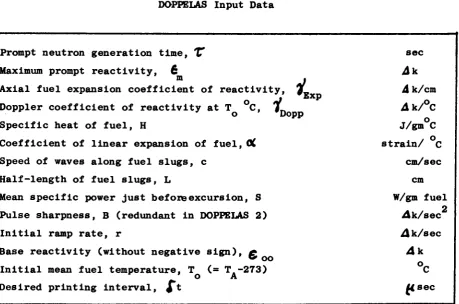
2.4 Programme Data
The physical data (with units) required before the above analysis can
be made to calculate a nuclear excursion are given in Table 2.1. Except
for one parameter (the sharpness B ) , the quantities shown are used in both
[image:18.595.56.516.304.608.2]versions of DOPPELAS. The parameter shown at the bottom of the table, the
Table 2.1
DOPPELAS Input Data
.
t
Prompt neutron generation time, f
Maximum prompt reactivity, 6 m
Axial fuel expansion coefficient of reactivity
Doppler coefficient of reactivity at T °C, #L
Specific heat of fuel, H
Coefficient of linear expansion of fuel, OC
Speed of waves along fuel slugs, c
Halflength of fuel slugs, L
Mean specific power just before excursion, S
Pulse sharpness, B (redundant in DOPPELAS 2)
Initial ramp rate, r
Base reactivity (without negative sign), g
Initial mean fuel temperature, T (= T.273)
o A
Desired printing interval, ¿ *
Exp
s e c Ak
Δ k/cm A k / ° C J/gm C s t r a i n / C
cm/sec cm W/gm f u e l
A k / s e c A k / s e c
A k °C M s e c
printing interval ¿t(üsec), is used to instruct the programme when to
Λ0
interpolate and print lines of results. The solution: Q(t), £ (t),...
Bias
etc, is printed at t = 0, St, 2 «Tt, 3 it right up to the end
of the excursion, the latter being measured by the levellingoff of Q(t).
11
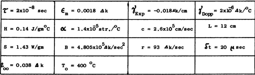
[image:19.595.60.565.354.502.2]Typical values of the above parameters for a SORA type reactor operating in the pulsed mode (i.e. for DOPPELAS 1) are given in Table 2.2. The pulse maximum β^ = 0.0018 Ak represents an accident in which the thermoelastic stresses fall just short of breaking the cladding of the highest rated fuel elements. The printout interval of 20 usee is enough in this case to re veal all details of the excursion without generating excessive output.
Table 2.2
Typical Numerical Values for DOPPELAS Input Data
~ - 8
X = 2x10 s e c Η = 0 . 1 4 j/gm°C
S = 1.43 W/gm
I = 0 . 0 3 8 Δ k oo
€ = 0 . 0 0 1 8 Ak m
OC = 1 . 4 x l Õ5s t r . / ° C
Β = 4 . 8 0 5 x l 05¿ k / s e c2
Τ = 400 °C o
i
ffExp
c =
r =
= -0.0184k/cm
5
= 2 . 6 x 1 0 cm/sec
= 93 A k / s e c
V
= 2xl¡0
€4k/°C
»Dopp
L = 12 cm
St = 20 u. s e c
Λ C C
c
t
CAL C CAL C C CAL C CALt
C C\LC
CAL C C CALs r p
5
1
s
Η
1
Í3
1
Ζ
Ζ
1
Ζ
i
Η
1
3
iZ
i
10k
% ζ6
Ζ
2Η
Ζ
Ρ
ñ
ι
Η>
ι
-/k
0 ( 7ti
i
νΖ
μ
0 φc
0 • Ûk-Ζ
-# 41
0 » • 4» « ♦ \ • 0 H-0i
»Ι
0 03
0 0 * Û * 0H-ï
% Cr 0 #ε
3
ε
ε
£ε
ε
3ε
1 D-t
ÍS % S S *k
i
%1
h>
« ■ 1i
0g
» 0st
% « 1û
i
t
0 0 ΰ ζ 0 0 f 0 • * • «3
Qtl·
β Û ù 0 0ε
ε
ε
ε
ε
ε
-Μs
s
s
5
5 G— Q
1
» 2 3 ù Û ψ • •i
¿ û 0 8 E Κs
2-f
zo
D • *
2
• 0 Q 0 0 ûε
-tob
— — ι
13
[image:21.595.60.549.98.783.2]these, the first 14 represent the physical parameters in exactly the same or der and format as in Table 2.2 while the last two registers, c(15) and c(16), are functionless and can be left blank. (For clarity and convenience,tbs exact correspondence between the programme C(J) registers and the physical para meters is given in Table 2.4). The card with CAL punched in columns 1, 2 and 3 directs the programme to the execution of case 1.
Table 2.4
Correspondence between the Programme Storage Registers and the Physical Parameters
c(D
= r
c ( 5 ) = H c ( 9 ) = S c(13) = £ _
OO
c(2)
=
e
m
c ( 6 ) = OL
c(lO) = Β c(14) = Τ o
c ( 3 ) = 7„ Exp c ( 7 ) = c c ( l l ) = r
c(4)
= V
wDopp
c ( 8 ) = L
c ( 1 2 ) = St
The remainder of Table 2.3 illustrates the manner in which a series of cases are assembled. After the execution of the first case described above, the programme automatically searches for new data. In the example given, the programme finds that it has to read only one number and store it in c(2). The old value of £ is then overwritten by the new and execution is
m
carried out with this new value of £ (= 0.0017 A k ) but with all other m
parameters preserved as in case 1. On completion of the second case, the programme then finds two cards, each with one parameter. The first goes into c(2) and the second into c(9). Thus, case 3 is executed with a new
—8
value of 6 (= O.C041m AK) and a new value of S (= 1.43x10 W/gm). Case
4 is a repetition of case 3, but with £ = 0.0042Ak. In case 5 the prompt
m -8 -8
14
repeats case 1, but with all reactivity feedback effects removed ( #_ = , Exp
j „ = O). The 7*th and last case restores the feedback effects but
« Dopp
increases the print-out interval it from 20 to 40 Msec and investigates the effect of a higher base reactivity — £ . All further execution is terminated by the card with STP punched in columns 1, 2 and 3 respectively,
The above examples have been designed to give a complete coverage of the input capabilities of DOPPELAS. Both versions of the programme are identical except that, in DOPPELAS 2, the register c(10) (= B) is redun dant and can be filled with any number whatever without effect.
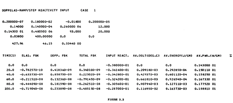
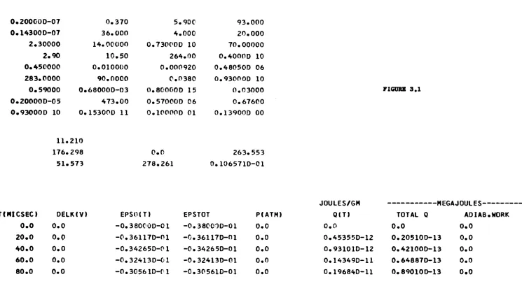
2.5 Programme Output
The output of the two versions of DOPPELAS, 1 and 2, is illustrated in Figures 2.1 and 2.2 respectively. These figures are copied directly from the output delivered by the IBM 360/65 printer, the input data being precisely that given in Table 2.2, i.e. the first case of Table 2.3.
The first line in the output of any case defines the version of the programme being used (pulse or ramp/step input) and the case number. Then follows four lines, each containing four numbers, which gives a complete listing (in the same format as in Tables 2.2 and 2.4) of the data being used in the case. In DOPPELAS 1, there then follows a line of four numbers
M.
giving respectively t (ea. (2.11)), t (eq. (2.10)), L/c (the wave ramp
transit along the slug half-length) and At (the finite difference inter
val, eq. (2.18)). In DOPPELAS 2, the line contains only three numbers:
t* (eq. (2.13)), L/c and At, since t is meaningless in this case, ramp
All of these times are stated in usee,
After the above preliminaries, the output gives the solution computed according to the method in section 2.3. There are eight columns of numbers, The l*st column gives the time in Msec at intervals of dt (= 20Msec in the examples). The 2*nd, 3»rd, 4»th, 5»th, 6*th, 7'th and 8*th columns
give respectively £_, , £Λ , £ , + £ , € , the average
β * Elas' Dopp' Elas Dopp' o'
DOPPELAS-PULSE REACTIVITY INPUT CASE 0.200000-0 7 0.14000 0.1430D Ol 0.03800 379.57 0.180000-02 O.140000-04 0.480500 06 400.00000 476.34 -0.01800 0.260000 06 93.000 0.0 46.15 0.200000-05 12.000 20.000 0.0
0 . 3 3 4 4 0 00
T(MICS) ELAS. FBK DOPP. FBK TOTAL FBK INPUT REACT. AV. DELTI D E C O AV. ENERGY! J/GM) AV.Ρ HR. ( W/GN) Ol
0 . 0 0 . 0
2 0 . 0 - 0 . 7 8 2 5 7 D - 1 0 4 0 . 0 - 0 . 6 3 3 7 3 D - 0 9 6 0 . 0 - 0 . 2 1 1 5 1 0 - 0 8 8 0 . 0 - 0 . 4 4 4 0 9 D - 0 8 1 0 0 . 0 - 0 . 7 1 9 0 4 0 - 0 8
DOPPELAS-RAMP/STEP REACTIVITY INPUT CASE O.2O000O-07 0.14000 0.14300 Ol 0.03800 427.96 0.180000-02 0.14000D-04 0.480500 06 400.00000 46.15 -0.01800 0.260000 06 93.000 0.0 0.33440 00 0.20000D-05 12.000 20.000 0.0
T(MICS) ELAS. FBK DOPP. FBK TOTAL FBK INPUT REACT. AV.DELT(DEG.C) AV.ENERGY«J/GM) AV.PMR.IM/GM)
0.0 0.0
20.0 -0.78257D-10 40.0 -0.63373D-09 60.0 -0.211510-08 80.0 -0.44409D-08 100.0 -0.71904D-08
0.0 0.418360-09 0.858750-09 0.132360-08 0.181590-08 0.23389D-08 0.0 0.340100-09 0.22502D-09 ■0.79145D-09 0.26251D08 ■0.48515D08
- 0 . 3 8 0 0 0 0 - 0 1 ■0.361400-01 - 0 . 3 4 2 8 0 D - 0 1 ■0.324200-01 - 0 . 3 0 5 6 0 0 - 0 1 - 0 . 2 8 7 0 0 0 - 0 1
0 . 0
0 . 2 0 9 1 8 0 - 0 3
0.42937D03 0.66181003 0.90794D03 0.11695002
0 . 0
0 . 2 9 2 8 5 0 - 0 4 0 . 6 0 1 1 2 0 - 0 4
0.92654D04
0 . 1 2 7 1 1 0 - 0 3
0.16373003
0 . 1 4 3 0 0 0 Ol 0 . 1 5 0 1 1 0 Ol 0 . 1 5 8 2 5 0 Ol 0 . 1 6 7 3 3 D Ol 0 . 1 7 7 5 2 0 Ol 0 . 1 8 8 8 1 0 Ol
[image:24.842.19.807.96.447.2]17
fuel Q (in Joules/gm) and the average power per gram of fuel Q (in Watts (gm). All reactivities are in units of A k measured relative to prompt criticality.
The calculation is stopped by a convergence criterion placed on the specific energy Q and this usually operates at the end of an excursion shortly after the total reactivity has fallen below prompt critical. If
(3) the solution is of interest beyond this point, as has been the case already, it is only necessary to remove the appropriate card from the programme deck. Users will find this a simple problem.
18
3. CLASSΒ EXCURSIONS; THE PROGRAMME SOREX 1
3.1 Theoretical Basis
A complex physicalmathematical model for the analysis of destructive
excursions in a pulsed fast reactor has recently been published in full (4)
detail and need not be greatly elaborated here. We shall simply sketch
the essential ideas and equations. Although the theory is developed ex
plicitly for type 1 accidents, it is easily adapted for the study of types
24, as will be seen in section 3.2.
(9)
The essential ingredient used in the theory is Nicholson's ' version (lo)
of the BetheTait model. In this, the only available shutdown mechanism
is the process of destruction caused by the generation of very large pres
sures in the core. Shutdown reactivity arises from the fact that core
material is accelerated along pressure gradients into regions of lower
importance. To describe this, and all other effects, the core is approx
imated by an equivalent sphere of radius R (=(3 "V /4TTJ , "J/" being the
C G c
core volume). Denoting t h e pressure by p ( r , t ) and the r e a c t i v i t y worth per u n i t volume of core m a t e r i a l by D ( r ) , t h e basic equation governing
*** (9 4)
the shut-down r e a c t i v i t y 6 in t h i s model i s '
Re
( 3 . 1 )
7F"
Pc J
9r ¿r
where 0¿ is the mean density of the core, r the radius variable and t the time.
The integral in (3.1) is evaluated by introducing three approximations. For the pressure, it is assumed that the dependence on the specific energy Q(r,t) (energy release per unit mass of fuel) falls into two linear re
\ 4,11) . it, it gions . A low pressure regime :
{
¿ f t ¿ « - « Í )
Iftf Q>«?
«<■ <52 2( 3 . 2 )
19
and a "high pressure regime":
(3.2)
I»-
i
α (β-Ο
if Q > Q*where O, is the effective density of the fuel (after expansion to fill
Λ) ΊΤ *) ♦ 4r
all voids) and l , Q , T and Q are constants. Q depends on these
3
*
*°
„;
constants. Note: with fø in gm/cm and Q, Q and Q_ in ergs/gm, / a n d
ΛΡ 2
fl *** 110 are dimensionless and ρ is in dynes/cm
For the specific energy Q(r,t) and reactivity worth density D(r) are assumed parabolic spatial distribution functions whose shape is unaffected
(9)
by the excursion :
Q(r, t) = Q.(t)(l- %.
ρ )
(3.3)
and
DO)«
ίο-ζΙΊξ
<
3·
4>
where Q (t) is the energy per unit mass of fuel at the core centre and q, g and g are determined by matching these formulae with the results of neutron transport theory.
Using (3.2), (3.3) and (3.4) in equation (3.1) it follows that
jpr
sy \ c * L
i\ft
c/
ζ
R5 j
( 3 5 )(4)
where S and S are functions of Q (t) and
20
In addition to the shutdown reactivity € , the theory also includes
the Doppler effect. The feedback reactivity coming from this effect is
represented by the same formula as in DOPPELAS, i.e.
Λ
where Q is the average specific energy release:
ff
(l-*rl)Q
0(t)
<
3'
8>
(4)
Η is the average specific heat of the fuel over the range of interest ,
Τ the absolute mean fuel temperature before the excursion and f
the Doppler coefficient of reactivity at temperature T .
Denoting, once again, the prompt reactivity input due to the accident
conditions by £ (t), the total prompt reactivity is given by
**£.(*) + $,.„(*)
+2V*>
(3.9)
(6)
In conjunction with this reactivity, it is again assumed
that the point
neutron kinetics model is applicable:
TQ
0* 6á
e+£.
0S,
(3.10)
where — £
is the prompt reactivity Just before the excursion (
€ ( t ^ =
— £ ) and
S is the initial specific power at the core centre, i.e.
oo
o
S
O
L »
τ
—
(3.11)
S being the mean initial power per unit mass of fuel. The boundary condi
tions to (3.10) are
Q (t,) ■
O and
Q (t. ) =
S , where t. is the time point
o b
o
b
o
D21
If the input reactivity
€
0(t) is given, it will now be noted that
equations (3.5),(3.7),(3.9) and (3.10) form a closed set with a unique
solution, Q (t). During the course of an excursion, Q (t) at first rises
o
o
slowly at a rate depending on S but accelerates very sharply when β
#> o.
#
After arrival at the threshold Q of the low pressure regime, the shut
~ z
down reactivity β becomes dominant very quickly and
Q (t) converges to
o
its final limit Q
(fio).
If M. is the total mass of fuel in the core, it
o
f
follows from (3.3) that the total energy release is given by
^ t
t t , a
0"
H )
M
f
Q*
(t)
(3i2>
the final value, Q . (°°), being very insensitive to the value of S.
In order to calculate the mechanical energy which may become available
for the creation of blasts and projectiles within the containment of the
reactor, an approximation similar to equation (3.2) is made. For a unit
mass of fuel with internal energy Q it is assumed that the available work,
. (4,11)
W , is given by '
B
C
if Q < w *
tø a
^
k ( a W
2* )
if W * < Q $ W *
(3.13)
"S
χ
(£-iy^
)
i f Q > w
♦
n
#
where
fc,
W , 2 , W and W are constants. It follows that the total avail
able work corresponding to the specific energy Q (t) at the centre of the
core is
I» c c
22
where r. and r_ are functions of Q (t)
1 Δ O
(4)
. The final available work W(60) is given by putting Q = Q (00) in (3.14).
o o
3.2 Reactivity Input
3.2.1 Reactfvit y^Ingut_due_to_Rotor_Breakage
In the absence of a grossly abnormal accident of the type to be out lined in this section, the reactivity input is given by equations (2.8) and (2.9), which, for convenience, are repeated here (with t measured relative to the peak):
e
#
(t)« max[
£„
0
(Ο
,'
-£
00
]
(3.15)where
É
P.tt>~
for t ^ t
for t V t f t (3.16) o o
for t > t
€ , B and r being respectively the normal maximum prompt criticality, the m
sharpness and the ramp rate of rise (fall) of the pulse. (For the defini tion of the other parameters, see section 2.2.1).
The effect of a rotor breakage accident (type 1) is, mathematically, to replace the above single reactivity pulse by a superposition of three sepa
(4)
rate pulses m This occurs because the different trajectories followed by
23
In the theory, the amplitudes of and time differences between these three pulse components depend on: the angle θ of the pulsation device at the instant of fracture relative to its position when the nomral re activity is a maximum, the radius R of the outer tip of the pulsation device, the speed V of the outer tip of the pulsation device, the effec
tive mass m of the fragment, the "reduced compressibility" % of
(4)
the coolant, the "rigidity" 0 of the fuel assembly, the "looseness" / (4)
QL of the core, the volume fraction f of the coolant, the volume o '
of the core, the total area A of the moving reflector presented to the core and the normal gap h separating the moving reflector from the core.
The above kinematic and dynamical parameters are not the only quanti ties to determine the reactivity input £ (t) from the three pulse
com-o
ponente. There is also the number of laminar pieces η built into the pul sation device (only one of which is assumed to break), the volume
coef-(4) /coef-(4) ficient of reactivity *W and "wobble" coefficient of reactivity £
All of these parameters provide the context for a description of the processes following a pulsation device breakage accident. In mathematical
(4) terms, this description boils down to the following set of equations :
(3.17)
where a and b are the relative reactivity worths of the unbroken and
η η
broken parts of the pulsation device respectively (i.e. in the simplest approximation b = l/n, a = 1-b ); y(t) is the fractional decrease in η η η
core volume satisfying
jj * ~ &
0(Ί) - %(*)
(3.18)
A V
with y= O for t <" t0 and y = - f_'—sin θ for t = t„,
24
4? χ'
fr
c
C^%^¿T£
V<3.19)
being proportional t o the force due t o the compression of the coolant,
for
yg«'Al
Ö L C * » N <
£Λ
β /ΛΛ_
Λ'
/ΛΛ\
,
(3.20)
for
y>oc/n
proportional to that due to the compression of the fuel slugs and t is
/ 2
the instant of impact: c (t) = e (t cos θ ) and
po po
O if t ^ t
£
(t)
=*
¿ £'V4mê (t-tj)
e'k
i fif
t * t.t
g^ t < t
2(3.21)
The times t., t„ and t are given by
2 3 g *
t
a
_fi
ie(eta^l)
c
2
Vti*.e
V
v2
'
and, for completeness, the breakage occurs at
The instant t, regarded as the starting point of an excursion, is given
D
when (3.17) begins to rise above — £ oo
25
3.2.2 Çgactivit2_Pulse_Ingut
A pure pulse form of reactivity input (for the study of type 2 and possibly type 3 accidents) can be obtained in SOREX 1 by making θ very small (e.g. θ » 0.1 ) and setting € = 0. It is easy to see physically, that, provided the gap h is nonzero, such a small angle fracture is un able to lead to a collision and that the terms in £ (t) and y(t) must
gap
therefore be absent from (3.17). Mathematically, it is even more obvious o '
since, with θ = 0.1 , € » O and h > O, the delay t in the collision Δ
pulse is very large (i.e. the reactivity input due to collision is ex cluded until much too late) while € 9 0. On the other hand, t„ = O
¿
-
gap 3and £ (t) = C (t). From this, it folows immediately that (3.17) re po po
duces to (3.15) as required.
3.2.3 React ivi t jr_Ramg_ Input
A ramp form of reactivity input (for the study of accident types 3 and o 4) can be achieved by first performing the above adjustments (Θ = 0.1 ,
£ = O, h > O) to give an input of the form (3.15) and then by raising £m
to a high value, e.g. fi = 1. The effect of the latter adjustment is to ensure that the ramp part of (3.16) extends well into the supercritical region and that the parabolic part can never be attained before destruction occurs.
3.3 Numerical Method
26
sions, however, which makes this procedure more critical, namely, the much larger fission powers generated. The quantities Q and Q* vary so
o o
rapidly when the excursion is at its peak that, in order to maintain good accuracy, it is necessary to decrease the spacing of the points t in
n this region.
Thus, defining
Δ*κ
st«+,
- ^
(3.22)we t a k e
At
C
i0~' sec
\
*I*¿K£-/<T*$
O-OOST/^
if
€(**)4ο
OOSt/eCtj]
S«c if
£ ( Î H ) > 0(3.23)
until the smallest value is reached and then keep At fixed at that
η
value until the end of the excursion (disassembly). In (3.23), £(t )
η
is given by (3.9) with t = t .
η
With the above time sequence, the finite difference representation of the kinetics equation (3.10) assumed in SOREX 1 is
«.fW^ftJ
*A> *
Q
'
(t
«-
y
At
A**.
f
(*** + **.)
27
Since Q (t ) = O and Q (t,) = S t, (where t. is the zeroth time point), O b ο 1 O 1 D
this equation leads to a step-by-step evaluation of the whole excursion provided £ (t ) is known, n
To evaluate £(t ), however, requires finite difference representations n also of equations (3.5) and (3.18). Equation (3.5) is approximated by
Δ£
η_, At*-.
H-2.4 (*«-,+"*-»> *"·'
- F „ - ,
C 3
·
2
"
where F is given by
*.!
-κ'
F
- f M - ^ ^ W )
R
e' - R
+
^ "V^J
e'
(4)
And S, and S are known in terms of Q (t ) . From (3.2) it is obvious ln^ 2n ο η -j that €*(t ) = 0 for all t satisfying Q (t X Q_ and this condition makes η η ο η is possible, with (3.25), a complete evaluation of β for all t .
The finite difference representation of equation (3.18) is based on the second order Taylor expansion:
Writing y(t ) = y , y(t ) = y and y(t ) = y , this becomes
η 'η η "η ' η ' η '
28
and defining
f (y)
=
G
t(y) +
G
$(y
)
(3.27)
it follows
immediately
from (3.18) that
¿L, »/<*«,)
<
3
·
Μ
>
while
the first derivative y
can
be evaluated by multiplying (3.18) by
and integrating over the interval (y _, y , ) :
η—2 η—1
¿< C -
X\ )
- -
ƒ ""' /ív'J'y'
«-a
If the integrand in this formula is now
expanded to first order in
(y'-y , ),
n—1
i.e.
f(v')
-/<*·.,) +<y - y^·) ƒ í y«.,)
then we get
(3.29)
Equations (3.26), (3.28) and (3.29) are now sufficient to
evaluate y step
by step if we introduce the starting conditions that y - O
for
t ^ t
and
y = A V sin
o c
θ/η V " for t = t_. The + sign in (3.29)
ζ
is used during the
29
The calculation is stopped either when the condition
is satisfied or when the input reactivity £(t) returns to — £ (which
ù oo
is symptomatic of a non-destructive excursion).
3.4 Programme Data
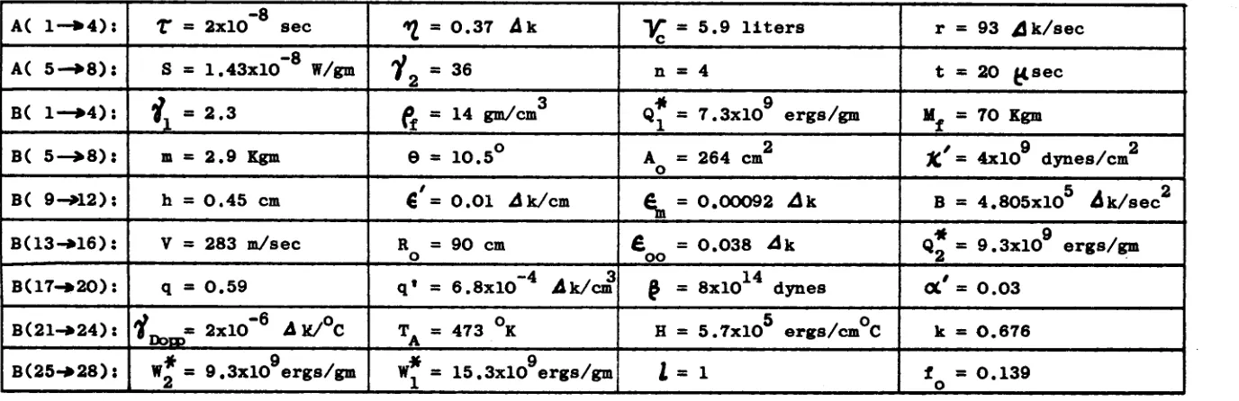
The physical data, along with the Fortran registers used to store them in the programme and the units required, are all listed in Table 3.1. The order in which the parameters appear is not strictly logical but has resulted from the natural evolution of the theory during its development. The quantity At(Msec) stored in register A(8) informs the programme at which time point t to interpolate and print the solu-tion Q (t) and all other quantities of interest. Typical values of the above parameters for a serious pulsation device breakage accident are shown in Table 3.2. This data represents approximately the maximum ac-cident of a SORA type reactor.
30
Table 3.1
SOREX 1 Input Data
Physical Parameter Fortran Register
A(l) A(2) A(3) A(4) A(5) A(6) A(7) A(8) B(l) B(2) BC3) B(4) B(5) B(6) B(7) B(8) B(9) B(10) B(ll) B(12) B(13) B(14) B(15) B(16) B(17) B(18) B(19) B(20) B(21) B(22) B(23) B(24) B(25) B(26) B(27) B(28) Unit sec
4k
liters Ak/eec W/gm fuel -U. sec -gm/cm ergs/gm Kgm Kgm degrees 2 cm dynes/cm cm /Ik/cm Ak Ak/sec m/sec cm Ak ergs/gm -Ak/cm dynes -dk/°C °Kergs/gm C
-ergs/gm
ergs/gm
-Prompt neutron generation time, Τ
Volume coefficient of reactivity, *Y)
Core volume, 1/1
Normal pulse ramp rise (fall) rate, r
Initial (source) power, S
Low pressure regime parameter, T»
Number of laminar parts in pulsation device, η
Printing interval, Δ t
High pressure regime parameter, 7.
Effective fuel density, ft.
■ff.
High pressure regime parameter, Q
Total mass of fuel, M
Effective mass of fragment, m
Pulsation device breakage angle, θ
Area of moving reflector towards core, A ' o
Corrected coolant compressibility, "JÇ
Gap between moving reflector and core, h
Wobble coefficient of reactivity, β
Normal pulse maximum, 6
Normal pulse shaprness, Β
Speed, outer tip of moving reflector, V
, , , I I tt t i tl I I _
R a d i u s , , R
' o
Base reactivity (without - sign), 6M
Low pressure regime parameter, Q
Å
Power shape factor, q
Reactivity worth shape factor, q* (eq. 3.6)
Fuel assembly rigidity, £
looseness, 0£
Doppler coefficient of reactivity,
Dopp Initial mean fuel temperature, T
Mean fuel specific heat, Η
Available work parameter, k
II It
w:
Table 3.2
Typical Values for the SOREX 1 Input Data
A( l - » 4 ) :
A( 5 - » 8 ) :
B( 1—»4):
B( 5—>8):
B( 9 - A 2 ) :
B ( 1 3 - » 1 6 ) :
Β ( 1 7 - » 2 0 ) :
B(21-»24):
B ( 2 5 - » 2 8 ) :
Τ = 2x10 s e c
S = 1 . 4 3 x l 0 ~8 W/gm
1
λ= 2.3
m = 2 . 9 Kgmh = 0 . 4 5 cm
V = 283 m/sec
q = 0.59
Y_ ■ 2xl0~
6AkV°C
"Donsw j = 9 . 3 x l 09e r g s / g m
*»2 = 0.37 Ak
y
2= 36
fi = 14 gm/cm θ = 1 0 . 5 °
€, = 0 . 0 1 ¿ k / c m
R = 90 cm o
q* = 6 . 8 x l 0 ~4 Ak/cm
TÄ = 473 °K
Λ
W* = 1 5 . 3 x l 09e r g s / g m
Υ = 5 . 9 l i t e r s
'c
η = 4
* 9
Q = 7.3x10 ergs/gm
A = 264 cm2
o
6 = 0.00092 Ak
£ = 0.038 Ak
oo
14
Ç = 8x10 dynes
5 « o H = 5.7x10 ergs/cm C
1 = 1
r = 93 ¿ k / s e c
t s 20 {¿sec
Mf = 70 Kgm
Χ = 4x10 dynes/cm Β = 4.805x1ο5 Δ k / s e c2
Ά 9 Q = 9.3x10 ergs/gm
OC* = 0.03
k « O.676
f ■ 0.139 o
1 ff 10
A 1 k Ζ- 0 ί
A
ç
y
i - k-z i
Β
f
ίκ 2-2
8 S % 2·1
Β 1 iZ ο · ί
β 13 1fr 2 * 3 - 0
î
17
20
OS
Β
21
2«
2-0
i
B
25
2%
? · 3 É
CA(
ãi
(»
<·
ι ι · ο
CAÍ
ß
fr
io
iO
Ό
CAL
β
¿
c o -i
b io a o ' o
CAL
AU, ík 10
Ό
Β 11 11 1 · 0
CKL
\ tl· S 20' 0
CAL
ST?
r
t5
'?
» TSi
t
fr1
à1t
?í
♦1
Ο
Ι
0
Ifr
1
) . ) . r3
1
0
W
* :•
ί
! § ■ ·
5
ί
(7
fr·• ί
5 ·
Oí3
ί7
)J
) .
0
% )
3
ν
i
ε-£
Ψ> tl·1
0
.
0
·
S-<f
it·' 0
7
2ú>ll·
000
0 3 *
S
S"
•
3
• 0
7*2
« 0
• 7
f ·<
£
ε
ε
ι
»β
111·
5
»
Ì3
ZO
ΊΟ
tl·*
L
) *0 ·
ί
> ·• • •
4
0
0
0
'
0
res
-?
0
fr1
•3
3
7ί>
3?
ε
£
E
7ô*?
S
?
ω to [image:40.842.27.758.58.478.2]33
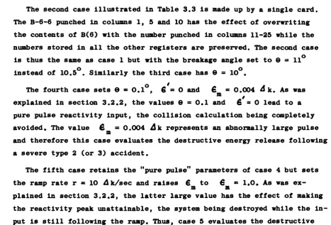
The second case illustrated in Table 3.3 is made up by a single card. The B-6-6 punched in columns 1, 5 and 10 has the effect of overwriting the contents of B(6) with the number punched in columns 11-25 while the numbers stored in all the other registers are preserved. The second case
is thus the same as case 1 but with the breakage angle set to θ = 11
o o instead of 10.5 . Similarly the third case has θ = 10 .
The fourth case sets θ = 0.1 , 6 = 0 and € - 0.004 ά k. As was
explained in section 3.2.2, the values θ = 0.1 and 6 * 0 lead to a pure pulse reactivity input, the collision calculation being completely
avoided. The value £ = 0.004 Δ k represents an abnormally large pulse
m
and therefore this case evaluates the destructive energy release following a severe type 2 (or 3) accident.
The fifth case retains the "pure pulse" parameters of case 4 but sets the ramp rate r « 10 /Ik/sec and raises € to 6 = 1.0. As was
ex-m ex-m
plained in section 3.2.2, the latter large value has the effect of making the reactivity peak unattainable, the system being destroyed while the in put is still following the ramp. Thus, case 5 evaluates the destructive energy release due to a type 3 or 4 accident for which the ramp input is 10 ilk/sec.
The sixth and last case repeats the latter calculation, but with r = 20 g
Δ k/sec and a greatly increased (factor 10 ) source power of S = 1.43 W/gm. The card with STP in columns 1, 2 and 3 terminates execution.
The illustrative cases given above are thought to provide an adequate coverage of the SOREX 1 input capabilities. Although none of the cases shown involves changing more than three quantities, the number of allowed changes is unlimited. The approximation b = l/n used in (3.1) can be modi fied if desired merely by changing a single card in the programme deck.
3.5 Programme Output
[image:41.595.72.540.107.424.2]