Development of a master controller for
a dual-arm underwater robot
Radzi Bin Ambar and Shinichi Sagara
Department of Mechanical and Control Engineering,
Kyushu Institute of Technology,
Tobata, Kitakyushu 804-8550, Japan
E-mail: [email protected]
Abstract: Master-slave system is a vital technique for controlling robot motions, especially in underwater robotics applications. This paper describes the development of a novel master controller for an experimental dual-arm underwater robot. By using the proposed master controller, a human operator is able to control an underwater robot movement in 3-dimensional space. The master controller also includes two units of 3-link manipulator controller. Moreover, each end-tips of the manipulator controller are attached with a joystick, one for controlling robot position, while the other controls robot attitude. The uniqueness of the proposed master controller is that a human operator is able to control the motion of robot base and two units of 3-link slave manipulator simultaneously. In this work, the hardware design of the proposed master controller and the structure of master-slave system are presented. The usefulness of the proposed master controller is verified through experiments on controlling an actual dual-arm underwater robot.
Keywords: Underwater Robot, Manipulator, UVMS, Control
1
Introduction
Underwater robotic technologies allow humans to ex-ecute intervention tasks in an efficient and safe way by reducing the risks of underwater operations. In-tervention capabilities are necessary to execute tasks such as valve manipulation using robotic arms in oil and gas related operations; conducting science ex-periments or collection of rocks and marine organ-isms; and maybe can be deployed for deep-sea search and rescue operation. Motivated by these, our re-search activities are related to the development of an Underwater Vehicle-Manipulator Systems (UVMS). UVMS is an unmanned underwater vehicle equipped with one or more robotic arms for intervention task.
Researchers of UVMS technology are develop-ing robots that can operate autonomously without any direct human intervention. Many researchers are focusing on autonomous control of underwater robot [1–4]. We have also proposed digital Resolved Acceleration Control (RAC) methods for single-arm and dual-arm UVMS [5, 6]. However, human op-erators are necessary for operating robotic arms because fully autonomous robotic arm manipula-tion technologies are still far from being perfected. Master-slave system is a common technique for con-trolling underwater robots. In master-slave sys-tem, a master controller is used to control the po-sition and attitude of a robot slave in 3-dimensional space from a distance. In the field of underwater robotics, especially related to semi-autonomous
un-derwater robots, there are not many research liter-atures discussing the designs and significant impact of master-slave system. In some research studies, game controllers and off-the-shelf manipulator con-trollers have been used as master concon-trollers [7–9]. Moreover, many studies are focusing on developing interface devices for single-arm manipulator applica-tions [7, 9–12]. Hence, development of a novel mas-ter controller that can control vehicle and multiple robotic arms movement simultaneously is necessary for efficient underwater intervention tasks.
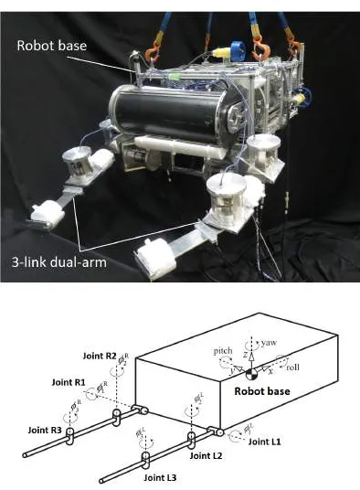
Fig. 1 3-link dual-arm underwater robot
The paper consists of three sections. In section 2, this paper describes the master-slave system of an underwater robot including the hardware design of the proposed master controller. Then, experiment method and results of the experiment are presented in section 3. Finally, conclusion is described in Sec-tion 4.
2
Master-Slave System
2.1 UVMS
Fig. 1 shows the underwater robot that is used in this work. Table 1 shows the physical parameters of the robot. The robot is consisting of a robot base (ve-hicle) and 2 units of 3-link manipulator. The robot is capable to move in three-dimensional space using six single propeller thrusters.
The control system for the robot base is based on RAC method proposed in [6]. The RAC method is consisting of the following equations of motion of the robot, desired accelerationαd(k) and desired
ve-locity νd(k) for robot base and both manipulator’s
end-tips are defined as follows:
u=M(q)αd+N(q, ζ)ζ+f (1)
αd(k) =
1
TW(k) ♯{ν
d(k+ 1)−νd(k)
+Λeν(k) +Tf(k)} (2)
νd(k) =
S0e
T {xd(k)−xd(k−1) +Γ ex(k−1)}
[image:2.595.71.268.67.335.2](3)
Table 1 Physical parameters of underwater robot
Base Link 1 Link 2 Link 3 Mass [kg] 104.52 5.90 2.86 1.40 Volume [×10−3 m3] 106.21 2.92 9.4 10.0
Moment of inertia 2.4 7.933 3.575 1.75 (x axis) [kgm2] ×10−3 ×10−3 ×10−3 Moment of inertia 2.4 7.933 23.24 13.97
(y axis) [kgm2] ×10−3 ×10−3 ×10−3 Moment of inertia 2.4 7.368 23.24 13.97
(z axis) [kgm2] ×10−3 ×10−3 ×10−3 Link length 0.870 0.093 0.305 0.335 (x axis) [m]
Link length 0.640 - - -(y axis) [m]
Link length 0.335 - - -(z axis) [m]
Link diameter[m] - 0.10 0.10 0.10 Added mass(x) [kg] 73.19 0.730 0.333 0.333 Added mass(y) [kg] 30.57 0.730 2.356 2.631 Added mass(z) [kg] 99.54 0.333 2.356 2.631 Added moment of 0.64 0.077 2.454 2.454 inertia (x) [kgm2] ×10−3 ×10−3 ×10−3 Added moment of 1.28 0.077 27 46.88 inertia (y) [kgm2] ×10−3 ×10−3 ×10−3 Added moment of 0.64 2.4 27 46.88
inertia (z) [kgm2] ×10−3 ×10−3 ×10−3 Drag coefficient(x) 1.2 1.0 1.0 1.0 Drag coefficient(y) 1.2 1.0 1.0 1.0 Drag coefficient(z) 1.2 1.0 1.0 1.0
where for Eq. (1) q = [xT0, ϕT]T and ζ =
[ ˙v0T, ϕ˙T]T, x0 is the position and attitude vector
of robot base, ϕ is the relative joint angle vec-tor, v0 is the linear and angular vector of robot
base, M is the inertia matrix including the added mass and inertia, N(q,ζ)ζ is the vector of Colio-lis and centrifugal forces, f is the vector consisting of the drag, gravitational and buoyant forces and moments, u = [fT
0, τ0T,τmT]T, f0 and τ0 are the
force and torque vectors of vehicle, τm is the joint
torque vector of manipulator. For Eqs. (2) and (3) eν(k) = νd(k)−ν(k) and ex(k) = xd(k)−x(k).
Here, ν = [νT
0, νeT ]T
, νe is the linear and
angu-lar vector of manipulator end-tips,xeis the position
and attitude vector of manipulator end-tips. xd is
the desired value of x= [xT
0, xTe]T, Λ = diag{λi}
andΓ = diag{γi}(i=1,· · ·, 12) are the velocity and
the position feedback gain matrices. Furthermore,
T is data sampling period and transformation ma-trix S0e = blockdiag{E3,Sψ0,E3,SψeR,E3,SψeL}, where
Sψ† =
coscosψψpp††cossinψψpp†† −cossinψψy†y† 00
sinψp† 0 1
.
(† = 0(=robot base), eR(=right arm
end-tip), eL(=left arm end-tip)), ψ† is attitude vector
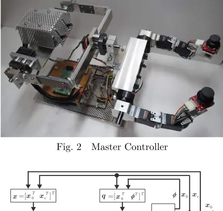
[image:2.595.317.535.89.410.2]Fig. 2 Master Controller
Eq. 1 Eq. 2
Eq. 3 UVMS
=[ ]T TT d
d
q=[ ]0 T
φT T x
ν=[ ]0 T T
e T x=[ ]0
T T T
x xe
xd ν α u
ν ν ζ ν0 φ
0
x
e x
φ x0 xe
φ ν0 νe
Fig. 3 RAC method block diagram.
unit matrix, W♯ is the pseudoinverse of W, i.e.
W♯=WT(W WT)−1, where
W =
[
C+E6 D
A B
] .
Here, AandB are matrices consist of position and attitude of robot base and manipulator’s joint an-gles, respectively. C is matrix for mass and D is matrix for inertia momentum. BothC and D ma-trices are included with hydrodynamic added mass and added inertia momentum which we assumed to be constant. Detail explanations regarding the sym-bols in the matrices can be found in [6]. Fig. 3 shows the block diagram of the RAC method.
2.2 Master controller
Fig. 2 shows the novel master controller developed in this work, consisting of a robot base main mas-ter controller, 2 units of manipulator masmas-ter con-troller and 2 units of robot base secondary master controller.
Fig. 4(a) shows the robot base main master con-troller. The robot base controller enables the user to control the motion of a slave robot in 3-dimensional space (3-DOF position and 3-DOF attitude) using only one hand. First, the translational motion of a robot (x, y and z axes) can be controlled using three slide-type potentiometers installed on a box-shaped controller of the robot base controller as shown in Fig. 4(b). The translational speed of the robot is
Fig. 4 Robot base main master controller
[image:3.595.317.538.73.656.2] [image:3.595.56.282.80.294.2]Fig. 5: Manipulator master controller and robot base secondary master controller
were arranged so that the axes is perpendicular to the center of the box-shaped controller. These servo actuators enable the control of rotational motion of the robot base (roll, pitch and yaw angles). Fig. 4(c) to (e) show the rotational motion when using the robot base main master controller.
Top half of Fig. 5(a) shows the 3-link dual-arm manipulator master controller. Each of the joints of the manipulator is consists of an RC servo actuator. These servo actuators are used to provide the desired joint angles for the manipulators of the slave robot including keeping any desired postures of the slave robot manipulators. Fig. 5(b) shows the manipula-tor master controller movements. Furthermore, at the end of each end-tips of the manipulator master controller is a robot base secondary master controller consists of a thumb joystick and a shaft potentiome-ter. These secondary controllers have similar func-tions as the robot base main controller which are to
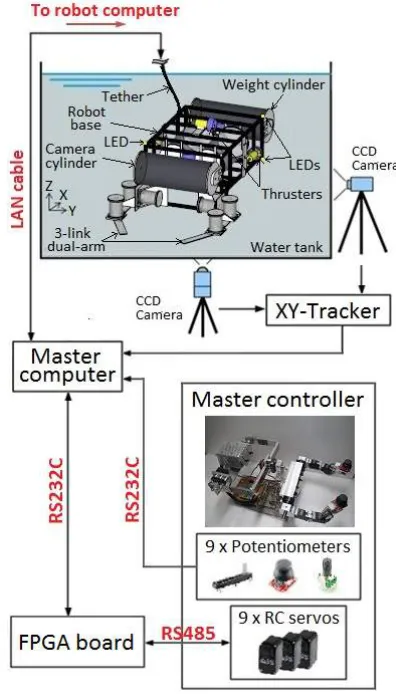
Fig. 6 Structure of the master-slave system
control robot base position and attitude. Below half of Fig. 5(a) shows the functionality of the controllers. Fig. 6 shows the structure of the master-slave sys-tem. A total of 9 units of servo actuators and 9 units of potentiometers are used in the proposed master controller. All potentiometers data are sent to A/D converter of a surface master computer. On the other hand, all servo actuators are connected to the master computer via an FPGA board. FPGA board is used to convert RS485 data signals into RS232 signals and vice versa.
3
Experiments
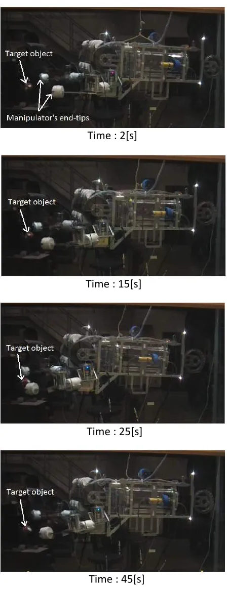
[image:4.595.323.521.76.423.2] [image:4.595.69.276.332.483.2]Time : 2[s]
Time : 15[s]
Time : 25[s]
Time : 45[s]
Fig. 7 UVMS motion during experiment.
period wasT = 1/20[s].
In the experiment, an operator was asked to per-form a simple task of moving both end-tips of the slave manipulator to a target object using the mas-ter controller. The operator was asked to use (a) the robot base secondary master controller to move the
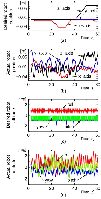
robot base and, (b) manipulator master controller to move the slave manipulator. Fig. 7 shows image sequences taken from video footage during the exper-iment. The master-slave operations started 2[s] from the start of the experiment. These images demon-strate that the robot was controlled to move towards the target object. After 25[s], both end-tips of the manipulator were controlled to be in the vicinity of the target object successfully. These can be further verified by observing the desired and actual manip-ulator joint angles data as shown in Fig. 8. Fig. 8(b) shows that the slave manipulator followed the de-sired joint angles of the manipulator master con-troller shown in Fig. 8(a). Furthermore, Fig. 9 show the time histories of the robot position and attitude during the experiment. The results demonstrate that the actual robot position and attitude corre-spond to the desired position and attitude. How-ever, the robot demonstrate large vibration during experiment due to the effect of the long data sam-pling period. Moreover, during the experiment, the operator only controlled the translational motion of the robot. Unfortunately, in Fig. 9(c), instead of producing 0[deg] results during the experiment, the desired rotational motions (roll, pitch and yaw an-gles) from the potentiometers produced inaccurate readings due to the inaccurate mapping of the po-tentiometer values with the required attitude angles. For future work, improvement on this area will be implemented. Nevertheless, the preliminary experi-ment demonstrate that the operator was able to con-trol the robot base and both end-tips of the manipu-lator simultaneously using the robot base secondary master controller and manipulator master controller.
4
Conclusion
In this work, we have proposed a master controller for a 3-link dual-arm underwater robot. By us-ing the proposed master controller, an operator is able to control an underwater robot movement in 3-dimensional space. The master controller also in-cludes two units of 3-links replica master arm. The uniqueness of the proposed master controller is that a human operator is able to control two units of 3-link manipulator and also controls the motion of un-derwater robot simultaneously. The usefulness of the proposed master controller was verified through ex-periments on controlling an actual 3-link dual-arm underwater robot.
References
[1] H. Maheshiet al., “A Coordinated Control of an Underwater Vehicle and Robotic Manipulator”,
[image:5.595.59.283.70.656.2][2] T. W. McLainet al., “Experiments in the Coor-dinated Control of an Underwater Arm/Vehicle System”, Autonomous Robots 3, Kluwer Aca-demic Publishers, pp. 213 – 232, 1996.
[3] G. Antonelli et al., “Tracking Control for Un-derwater Vehicle-Manipulator Systems with Ve-locity Estimation”,IEEE J. Oceanic Eng., Vol. 25, No. 3, pp. 399 – 413, 2000.
[4] N. Sarkar and T. K. Podder, “Coordinated Mo-tion Planning and Control of Autonomous Un-derwater Vehicle-Manipulator Systems Subject to Drag Optimization”,IEEE J. Oceanic Eng., Vol. 26, No. 2, pp. 228 – 239, 2001.
[5] S. Sagara et al.,“Digital RAC for Underwa-ter Vehicle-Manipulator Systems Considering Singular Configuration”, J. Artificial Life and Robotics, Vol. 10, No. 2, pp. 106 – 111, 2006. [6] S. Sagara and R. Bin Ambar,“Digital Resolved
Acceleration Control of Underwater Robot with multiple manipulators”, Proc. of 2014 Int. Conf. on Advanced Mechatronic Systems
(ICAMechS), pp. 232-237, 2014.
[7] S.-U. Leeet al.,“Development of a Tele-operated Underwater Robotic System for maintaining a light-water type power reactor”, Proc. of Int.
Joint Conf. SICE-ICASE, pp. 3017-3021, 2006.
[8] B. H. Jun et al., “Workspace control system of underwater tele-operated manipulators on ROVs”,Proc. of OCEANS 2009-EUROPE, pp. 1-6, 2009.
[9] F. Takemura and R. T. Shiroku, “Development of the actuator concentration type removable underwater manipulator”, Proc. of 11th Int. Conf. on Control Automation Robotics and
Vi-sion (ICARCV), pp. 2124-2128, 2010.
[10] S. Soylu et al., “Comprehensive underwa-ter vehicle-manipulator system teleoperation”,
Proc. of OCEANS 2010, pp. 1-8, 2010.
[11] J. J. Yaoet al.,“Development of a 7-function hy-draulic underwater manipulator system” Proc. of 2009 IEEE Int. Conf. on Mechatronics and
Automation, pp. 1202-1206, 2009.
[12] K. Kawano, T. Shimozawa, and S. Sagara, “A Master-Slave Control System for a Semi-Autonomous Underwater Vehicle-Manipulator System”, Artificial Life and Robotics, Vol.16, pp. 465-468, 2012.
0 20 40 60
−50 0 50
0 20 40 60
−50 0 50 Time [s] [deg] Time [s] [deg]
Desired joint angle
Actual joint angle
(a) (b) Joint R3 Joint L2 Joint R1 Joint L1 Joint R2 Joint L3 Joint R3 Joint L2 Joint R1 Joint L1 Joint R2 Joint L3
Fig. 8 Time history of manipulator’s joint angles
0 20 40 60
−0.04 0.01 0.06
0 20 40 60
−0.04 0.01 0.06
0 20 40 60
−2 0 2
0 20 40 60
[image:6.595.355.494.73.345.2]−2 0 2 Time [s] [m] Desired robot (a) z−axis x−axis y−axis Actual robot z−axis y−axis x−axis (b) [m] Desired robot Actual robot [deg] [deg] Time [s] Time [s] (c) (d) roll pitch yaw pitch roll yaw position position Time [s] attitude attitude
[image:6.595.336.511.383.728.2]