PERFORMANCE OF PHYSICAL SHELL FOUNDATION MODEL UNDER AXIAL LOADING
AMERA RATIA BINTI AB RAHMAN
A thesis submitted in partial
fulfilment of the requirement for the award of the Degree of Master of Civil Engineering
Faculty of Civil and Environmental Engineering Universiti Tun Hussein Onn Malaysia
ACKNOWLEDGEMENTS
First and foremost, I would like to thank Allah for the time, strength and wisdom that have been given to me for the completion of this thesis. This interesting research work undertaken in the development of this academic piece would not have been possible without the contributions and support of the following people:
I appreciatively acknowledge the guidance, understanding, inspiration and feedback from my supervisor, Prof. Dr. Devapriya Chitral Wijeyesekera and Prof. Dato Dr Ismail Bin Bakar throughout this research attempt. Not to forget, my sincere gratitude to Dr. Agus Sulaeman who have been appointed as my co-supervisor for his time and research consultations in this research.
Meanwhile, the experimental work would not have been possible without the assistance and invaluable insight from Mr. As'shar Bin Kasalan and exceptional technical knowledge from laboratory technicians Madam Norkama Azura bte Dolah and technician in Recess with whom I had the privilege of working with.
Also, many thanks to my colleagues in RECESS 2 for their unending support and inexorable assistance.
ABSTRACT
ABSTRAK
TABLE OF CONTENTS
TITLE i
DECLARATION ii
DEDICATION iii ACKNOWLEDGEMENT iv
ABSTRACT v
ABSTRAK vi
TABLE OF CONTENT vii
LIST OF TABLES xi
LIST OF FIGURES xiii
LIST OF NOTATIONS xviii
LIST OF APPENDICES xxi
CHAPTER 1 INTRODUCTION 1.1 Introduction 1
1.2 Problem statement 4
1.3 Aim of the research 5
1.4 Objectives of the research 5
1.5 Scope of research 6
1.6 Significance of the research 7
CHAPTER 2 LITERATURE REVIEW
2.1 Background of research 9
2.2 Foundation in general 9
2.3 Conventional foundation 12
2.4 Shell foundation 14
2.4.1 The concept of shell structure 15 2.4.2 Fundamental theory of shell structures 16 2.4.3 Types of shell foundation 19 2.4.4 Critical review of past research 24 2.4.4.1 Structural performance 24 2.4.4.2 Geotechnical behavior 27 2.4.5 Development of shell foundation in field 36 2.5 Concept of distribution load in shell and flat 38
foundation
2.6 Modulus of subgrade reaction coefficient 40 2.7 Relationship between bearing capacity and modulus
of subgrade reaction, ks 45
2.8 Modelling of foundation model 46
2.9 Parametric study 48
2.10 Shell structural strength (crack pattern) 49
2.11 Chapter summary 54
CHAPTER 3 RESEARCH METHODOLOGY
3.1 Introduction 55
3.2 Flow chart of research 55
3.3 Preliminary studies 57
3.3.1 Foundation material selection 57 3.3.2 Material testing selection 57
3.4 Laboratory testing conducted 58
3.4.2 Direct shear test 60
3.4.3 Specific gravity 64
3.4.4 Compression test 65
3.5 Development of fabrication 66
3.5.1 Foundation model 66
3.5.1.1 Parametric study 66
3.5.1.2 Geometry and dimension of 69 foundations model
3.5.1.3 Method of modelling 74 3.5.2 Design and construction of soil text box 76
3.6 Experimental test procedure 80
3.7 Calibration of strain gauge 82
3.8 Data analysis 85
3.9 Chapter summary 85
CHAPTER 4 RESULT AND ANALYSIS
4.1 Introduction 86
4.2 Substructure foundation simulation 87 4.2.1 Simulation of elastic sponge substructure 87
foundation
4.2.2 Simulation of particulate 89 substructure foundation (sand)
4.2.3 Discussion of square flat 91 superstructure foundation performance
4.3 Study of three foundation shape with different 92 aspect ratio(h/B)
4.3.1 Square flat foundation (F) 93 4.3.2 Pyramidal shell foundation (P) 96 4.3.3 Hyperbolic paraboloid shell foundation (H) 99 4.3.4 Discussion on the study of foundation shape
4.4 Influence of foundation depth (d/B) with different
aspect ratio (h/B) 106
4.4.1 Square flat foundation (F) 106
4.4.2 Pyramidal shell foundation (P) 107
4.4.3 Hyperbolic paraboloid shell foundation(H) 109 4.5 Relationship between bearing capacity effect of 110 aspect ratio (h/B)/ slenderness of foundation base (t/B) to modulus of subgrade reaction, ks. 4.5 Strain gauge structural performance 117
4.6 Crack pattern 122
4.6.1 Square flat foundation (F) 122
4.6.2 Pyramidal shell foundation (P) 125
4.6.3 Hyperbolic paraboloid shell foundation (H)128 4.7 Chapter summary 131
CHAPTER 5 CONCLUSION AND RECOMMENDATION 5.1 Introduction 134
5.2 Conclusion 134
5.3 Recommendation for further research 136
REFERENCES 138
LIST OF TABLE
2.1 Prime references used in the research 9
2.2 Types of conventional foundation and its characteristic 12 2.3 Innovative shape foundation and its corresponding
geometry equation
17
2.4 Mayerhof’s shape, depth and inclination factors 28
2.5 Properties of sand for different value of ɸ 30
2.6 Properties of clay for different value of cohesion ,c 31
2.7 Failure load versus c– ɸ values. 32
2.8 Parameter and results of laboratory test 32 2.9 Load–settlement results for variable shell thickness 48
3.1 List of laboratory testing conducted 57
3.2 Friction angles of granular soils 60
3.3 Normal stress and the corresponding maximum shear stress, τn
60
3.4 Parameter used in the parametric study 66
3.5 Load–settlement results for variable shell thickness 66 3.6 Load–settlement results for variable width foundation 67 3.7 Geometrical configuration and dimension of foundation
models
69
4.1 Load carrying capacity for square flat foundation 91 4.2 Analytical data from equivalent plan stress variation for
square flat foundation with displacement/base width (z/B) ratio graph.
95
4.3 Analytical data obtained from equivalent plan stress variation for pyramidal shell foundation with displacement/base width (z/B) ratio
4.4 Analytical data from equivalent plan stress variation for hyperbolic paraboloid shell foundation with displacement/base width (z/B) ratio.
101
4.5 Comparison on equivalent plan stress variation for pyramidal shell foundation and square flat foundation with displacement/base width (z/B) ratio for elastic sponge foundation and surface of sand.
103
4.6 Comparison on equivalent plan stress variation for hyperbolic paraboloid shell foundation and square flat foundation with displacement/base width (z/B) ratio for elastic sponge foundation and surface of sand.
104
4.7 4.8
Analysis of shell gain factor and settlement
Summary analysis of equivalent plan stress variation for foundation embedded in sand with
displacement/base width (dz/b) ratio.
104 109
4.9 Data on surface of sand and sponge of foundation on the relationship of bearing capacity and modulus of subgrade reaction
114
4.10 Data on embedded of foundation on the relationship of bearing capacity and modulus of subgrade reaction.
115
4.11 Relationship of bearing capacity and modulus of subgrade reaction on different coefficient of determination, R2.
115
4.12 Relationship of bearing capacity and modulus of subgrade reaction on linear correlation.
116
4.13 Analysis of crack pattern for square flat foundation 121 4.10 Analysis of crack pattern for pyramidal shell
foundation
125
4.11 Analysis of crack pattern for hyperbolic paraboloid shell foundation
LIST OF FIGURES
1.1 Planar structure 2
1.2 Structures using biomimetic concepts 3
1.3 Boundaries of research 6
2.1 Types of soil structure interaction 11
2.2 Overview of shallow and deep foundation 12
2.3 Fundamental theory of shell structures 15
2.4 Case for worst condition on footings 16
2.5 The hyperbolic paraboloid conditions 17
2.6 Conical shell foundation 18
2.7 The inverted spherical dome raft 19
2.8 Detail of hyper footing 20
2.9 Elliptic paraboloid shell raft 21
2.10 Funicular shell footing 22
2.11 Folded plate shell footing 22
2.12 Variation of failure load with cohesion. 31
2.13 The shell efficiency-shell raises ratio for shell footings with and without reinforcement at different relative density
34
2.14 Contact pressure distribution 37
2.15 Distribution of bearing pressure along the base of shallow foundation subjected to concentric vertical loads
38
2.16 Normal and vertical contact pressure distributions 39 2.17 Influence on width of the loaded area to settlement 40 2.18 Stress bulbs based on Newmark’s solution to Boussinesq’s
equation for a square and continuous footings
40
2.19 Modulus of subgrade reaction concept 42
2.21 The relationship between subgrade reaction ksand depth
of foundation for different shapes of footing for angle of internal friction ø = 30°.
43
2.22 The relationship between subgrade reaction ks and depth
of foundation for different shapes of footing for angle of internal friction ø = 36°.
44
2.23 Different types of laboratory scale model of shell foundation
46
2.24 Ultimate failure of plate 49
2.25 Ultimate failure of shell 49
2.26 Ridge failure 50
2.27 Diagonal failure 50
2.28 Ridge failure mechanism of hyper footing 50
2.29 Diagonal collapse mechanism of hyper footing 51 2.30 Collapse model for four different modeling 53
3.1 Flow chart of research 55
3.2 Particle size distribution of sand used in the soil box 59 3.3 Shear stress versus horizontal displacement graph 61
3.4 Failure envelope for sand 62
3.5 Stress- strain curve for sand 62
3.6 Deformation curve of sponge 65
3.7 Effect of shell thickness (t) on load–carrying capacity 68 3.8 Effect of width foundation (B) on load–carrying capacity. 68
3.9 Geometrical configuration of foundation 69
3.10 Schematic on the backside of shell foundation 71
3.11 Types of foundation and materials 72
3.12 Thickness measurement using micrometres for plaster of Paris model.
74
3.13 Overview of soil box 75
3.14 Schematic design of soil box 76
3.15 Total zone of influence of failure pattern 77 3.16 Adoption of direct shear apparatus into soil box
fabrication
3.17 Dimensional specification of soil box 79
3.18 Trial sand box 80
3.19 Definition of strain 81
3.20 Data taker DT80M 82
3.21 Dimension of material to adjust in the universal testing machine
82
3.22 Calibration preparation 83
4.1 Axial load –deformation curve for square flat polyester resin under elastic substructure sponge foundation for one cycle up to 50 % failure.
87
4.2 Diagram of rectangular flat polyester resin foundation rested on the top of elastic sponge substructure surface.
87
4.3 Axial load –deformation curve for square flat polyester resin under sand particulate substructure foundation for one cycle up to 50 % failure.
89
4.4 Load carrying capacity on different plate thickness 91 4.5 Equivalent plan stress variation for square flat foundation
with displacement/base width (z/B) ratio.
93
4.6 Equivalent plan stress variation for pyramidal shell foundation with displacement/ base width (z/B) ratio.
96
4.7 Equivalent plan stress variation for hyperbolic paraboloid shell foundation with displacement/base width (z/B) ratio.
99
4.8 Equivalent plan stress variation for square flat foundation with displacement/base width (z/B) ratio.
106
4.9 Equivalent plan stress variation for pyramidal shell foundation with displacement/base width (z/B) ratio
107
4.10 Equivalent plan stress variation for hyperbolic paraboloid shell foundation with displacement/base width (z/B) ratio.
108
4.11 Relationship between bearing capacity and modulus of subgrade reaction for square flat foundation on surface of material testing.
4.12 Relationship between bearing capacity and modulus of subgrade reaction for hyperbolic paraboloid shell foundation on surface of material testing.
111
4.13 Relationship between bearing capacity and modulus of subgrade reaction for pyramidal shell foundation on surface of material testing.
112
4.14 Relationship between bearing capacity and modulus of subgrade reaction for square flat foundation embedded into the material testing.
112
4.15 Relationship between bearing capacity and modulus of subgrade reaction for hyperbolic paraboloid shell foundation embedded into the material testing.
113
4.16 Relationship between bearing capacity and modulus of subgrade reaction for pyramidal shell foundation embedded into the material testing.
113
4.17 Location of strain-gauge attached on laboratory scale foundation
118
4.18 Schematic of strain gauge location 118
4.19 Strain versus load on different strain gauge position of foundation
119
4.20 Strain versus displacement over base width ratio (z/B) on different strain gauge position of foundation
120
4.21 Crack pattern occurred on sand surface of square flat foundation under different slenderness to base foundation (t/B)
122
4.22 Close up on crack pattern induced on square flat foundation of 0.5 slenderness of base foundation (t/B).
123
4.23 Crack pattern occurred on sand surface of pyramidal shell foundation under different aspect ratio (h/B).
125
4.24 Typical crack initiation and propagation of pyramidal shell foundation.
126
4.25 Crack pattern on sand surface of hyperbolic paraboloid shell foundation under different aspect ratio (h/B).
4.26 Typical crack initiation and propagation of hyperbolic paraboloid shell foundation
LIST OF NOTATIONS
NOTATION DESCRIPTION UNIT
ø Angle of shearing resistance of sand ˚
δu Settlement at unit load m
δ Deflection/ deformation m
δv Vertical deflection/ deformation m
σ Stress kPa
σn Normal stress N/mm2
σ’ Effective stress kPa
ɣ Unit weight of soil kN/m3
ɣdry Unit weight of dry sand kN/m3
ɣw Unit weight of water kN/m3
ρdry Dry density of soil kN/m3
ρw Density of water kN/m3
ε Strain mm/mm or %
τxy, τf Maximum shear stress N/mm2
λcs, λqs, λys Shape factor -
λcd, λqd, λyd Depth factor -
Λci, λqi, λyi Inclination factor -
∆L Absolute change in length m
∆R Change in strain gauge resistance Ohm
A/Ap Area m2
Ah Area of footing in horizontal projection m2 A’ Base area of counterpart circular and square
foundations
mm
a’ Area of the flat portion of the base of shell and flat foundations
B Width of foundation mm
b Width of column mm
Cu Coefficient of uniformity -
Cc Coefficient of curvature -
c Cohesion of soil -
D Depth of foundation mm
D10 Percentage of soil having size corresponding to
10 % passing
-
D60 Percentage of soil having size corresponding to
60 % passing
-
d/B Embedded depth ratio -
Df/B Deth over breadth ratio -
dz Deflection/ deformation m
E Young modulus kN/m2
e Void ratio -
F Square flat foundation -
Fδ Non dimensional settlement factor -
GF Gage factor -
Gs Specific gravity -
H Hyperbolic paraboloid shell foundation - h Height of the foundation
h/B Aspect ratio -
Ks Modulus of subgrade reaction kN/m
L Length of foundation mm
l Length of column mm
M Bending stress resultant kN
M Mass of soil kg
m1 Mass of density bottle and stopper gram
m2 Mass of density bottle plus stopper plus oven
dried soil
gram
m3 Mass of density bottle plus stopper plus soil
plus distilled water
m4 Mass of density bottle plus stopper plus
distilled water
gram
Nq, Nc, Nϒ Terzaghi’s bearing capacity factors -
N Membrane stress kN
P Pyramidal shell foundation -
pv Resultant contact pressure (vertical) kN/m2
pn Resultant contact pressure (normal) kN/m2
Po’ Effective stress at the level of the bottom of foundation
N/mm2
p Reaction kPa
Q Load/force applied on foundation during testing
kN
Qu/qu Ultimate load kN
Qus Ultimate load of shell footings kN
Quf Ultimate load of flat footings kN
q Reaction pressure/stress kPa
q Load per unit area N/m2
x
q The component of loading -
qbmax Maximum plane stress kPa
q/w Bearing load/ weight ratio -
R Unstrained resistance of strain gauge Ohm
SF Shell factor -
t Thickness on the foundation mm
t/b Slenderness ratio of foundation base -
V Volume of soil m3
w Vertical deformation m
y Deflection m
z Displacement that occurs at the column foundation interface due to loading.
mm
LIST OF APPENDICES
APPENDIX TITLE PAGE
A Dry sieve analysis data and calculation 144
B Specific gravity of sand data 145
C Compression test of sponge data 146
D Calculation of sand in soil box 147
E Conceptual study on the application of rectangular hyperbolic paraboloid shell foundations in soft soils
148
F Influence of alternative foundation shape on their load bearing characteristics
INTRODUCTION
1.1 Introduction
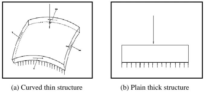
Foundation is the unseen part of an engineering structure, but still the most important as it is necessarily supporting layer of the structure. Moreover, the foundation is also known as the most fundamental requirement that transfers all load components from the superstructure onto the subsoil. The concept of adopting shells in foundation design is not new as it has been introduced in the construction industry since the structure adoption of inverted brick arch foundation (Huat et al., 2007). Nevertheless, in the mid-1950’s, shell structure had entered into the world of foundation engineering which was first introduced by Felix Candela for the construction of the Mexico City Customs House (Hanna & El- Rahman, 1990). Examples of shell structures in civil engineering are large-span roofs, liquid-retaining structures, water tanks, concrete arch domes and others (Eduard & Theodor, 2001).
[image:22.595.149.487.89.264.2]
(a) Curved thin structure (b) Plain thick structure
Figure 1.1: Planar structure
bodies derived in the three-dimensional theory of shells was obtained simply by replacing the reference configuration of a general body with that of a shell. In the realm of structural shell theories, curved thin structures deform and behave differently to planar thick structures as shown in Figure 1.1.
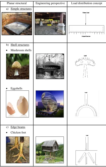
Planar structural Engineering perspective Load distribution concept a) Simple structures
b) Shell structures Mushroom shells
Eggshells
[image:23.595.107.529.67.729.2]c) Edge beams Chicken feet
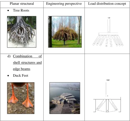
Planar structural Engineering perspective Load distribution concept Tree Roots
d) Combination of shell structures and edge beams
[image:24.595.107.531.67.460.2] Duck Feet
Figure 1.2: Structures using biomimetic concepts (continued)
1.2 Problem statement
soils characteristic make them inadequate to support additional load of structure build on them (Chan et al., 2010). Soft soil especially peat (represented here by spongy material) as peat soils are considered as spongy material. Thus, these situations require large sized foundation because of the low bearing capacity (Salunkhe et al., 2016).
Thus, to replace the existing problem in the foundation, shell foundation is one of the promising shallow foundationsto be considered to overcome the problem of foundation in special condition. Shell foundation was built to transfer heavier superstructure loads to weaker foundations soils. Compared to traditional foundation, shell foundation act mostly in tension and compression and will be more efficient and economical in such situations. Even in smaller foundation, the amount of materials that is necessary for a shell to carry a load will be considerably minimum than that required for bending member such as beams and slabs. However, the labour involved in shell construction will be more than that is necessary for traditional type of flat foundations.
1.3 Aim of the research
The aim of this research is to assess the performance (bearing capacity and modulus of subgrade reaction) of structural and geotechnical aspects of shell and flat foundations in different conditions (sand and sponge) through laboratory model testing.
1.4 Objectives of research
In order to fulfill the aim of this study, the main objectives of the research are listed as follows:-
a) To compare the effect of aspect ratio (h/b) and embedment ratio on the relationship of bearing capacity with modulus of subgrade reaction.
b) To investigate laboratory physical models to locate zones of stress and strain concentrations.
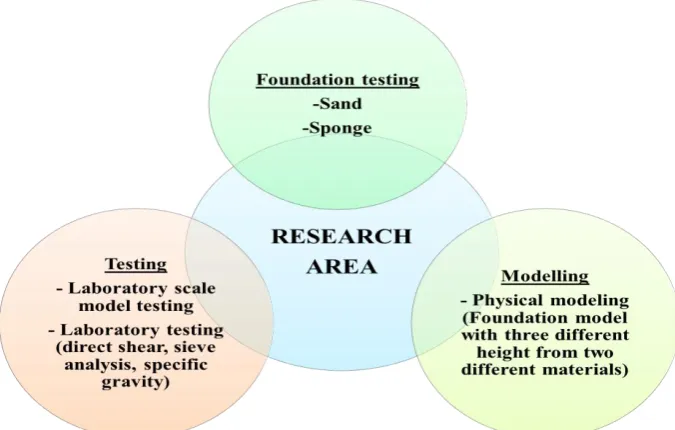
1.5 Scope of research
[image:26.595.150.488.408.623.2]Figure 1.3 shows the chart boundaries of research. It consists of three important elements; modelling, foundation material testing and testing. The most important part in this research is the fabrication of physical modeling which mobilize the entire project. Physical modelling comprises of the square flat foundation, pyramidal shell foundation and hyperbolic paraboloid shell foundation which produce from Plaster of Paris and polyester resin. All foundation was then tested with a different material testing condition where it is loaded on sponge and sand either on two conditions example, the surface or embedded condition. Before undergoing foundation load testing, the determination of geotechnical material testing (sponge and sand) was carried out to obtain the material testing properties. Then, foundation load testing was conducted by placing the foundation models at the center of a soil box and loaded. The data was then analyzed graphically and compared with past researcher’s work.
1.6 Significance of the research
The research with expected outcomes shows innovative shape foundation will have better performance compared to the traditional ones. The outputs achieved from this research can be used as guidance to the behavior of prototype shell foundations. Thus, new idea on prefabricated foundation product will be planned to be created. Furthermore, the construction world will get a new idea to share on physical modeling in the field.
1.7 Structure of the thesis
[image:27.595.109.517.402.752.2]Table 1.1 is a summary on the content of the thesis and it is outlined sequentially into chapter, titles and descriptions.
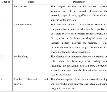
Table 1.1: Structures of thesis.
Chapter Titles Description
1 Introduction This chapter includes an introduction, problem
statement, aim of the research, objective of the
research, scope of work, significance of research and
structure of the research.
2 Literature review The literature review is a critically written and
comprehensive account of what has been published
on a topic by accredited scholars and researchers. It is
directly related to the thesis, providing information on
theories, models, materials and technique. This
includes the research on the design consideration and
concept of the alternative foundation.
3 Methodology This chapter is an important chapter as it explains in
detail about the laboratory work starting from
modelling the foundation and soil box, procedures
accounted on testing and the data gathering methods
used in the research.
4 Results, observation and
analysis.
This chapter explains about the data from the testing
and the results were analyzed and interpreted using
Table 1.1: Structures of thesis. (continued)
Chapter Titles Description
5 Conclusion and
recommendations
This chapter concludes a summary of resulted obtain
from present work and discussion was made by
comparing result taken with the results from the
previous researcher. This chapter also will place
recommendations made from this research for better
research in the future.
References A list of references will be included in this thesis
Appendix Appendix used in the thesis can be found at the end
CHAPTER 2
LITERATURE REVIEW
2.1 Background of research
This chapter was extended with the comprehensive and critical review of past research by gathering and discussing the geotechnical and structural properties associated with shell foundation. The chronology of the critical review was on the definition of foundation, types of foundation (conventional and alternative foundation), the concept of shell foundation, critical studies and application of shell foundation is included in this chapter. Throughout this research, some references had been used. Table 2.1 shows the five prime references that support the research.
2.2 Foundation in general
Table 2.1: Prime references in the research
Author Year Title Conclude remarks Conclusion
Hanna, A.M. and
Abdel-Rahman, M. 1998 Experimental investigation of shell foundation on dry sand
The ultimate bearing capacity of shell foundation is higher than flat
counterpart and the ultimate bearing capacity increases with the
increase of shell angle.
As a conclusion made from this
prime references, the important
parameter that plays an
important roles in this model
footing test was shell angle,
shell thickness, angle of
shearing resistance, height and
dimension of soil core and
embedment depth ratio which
resulted to ultimate bearing
capacity and load carrying
capacity. Huat B.B.K.,
Mohammed T.A.,
Abang Ali A.A.A
and Abdullah A.A
2007
Numerical And Field Study On
Triangular Shell Footing For
Low Rise Building
The load carrying capacity of the inverted triangular higher than the
‘upright’ triangular shell footing and conventional flat footing.
Furthermore, the load carrying capacity of shell footings was found to
increase with the increase of shell angle and shell thickness.
Fernando N.,
Sendanayake
E.,Sendanayake D., &
Silva, N. D
2011
The experimental investigation
of failure mechanism and
bearing capacity of different
types of shallow foundations
The ultimate capacities of shell foundations are higher than that of their
flat counterparts with the same plan dimensions.
Esmaili D. And Hataf
N. 2013
Determination Of Ultimate
Load Capacity Of Conical And
Pyramidal Shell Foundations
Using Dimensional Analysis
By increasing the dry unit weight, angle of shearing resistance, relative
density of sand, ultimate load capacity of shell foundations also
increased. Therefore, the influence of angle of shearing resistance and
increase of height and dimension of soil core (b, H) leads to on the
ultimate load values.
Azzam, W. R. and
Nasr, A. M. 2014 Bearing capacity of shell strip footing on reinforced sand.
The load carrying capacity of the shell footing on reinforced dense
subgrade was found to increase when the embedment depth ratio
increased, and the increases in the angle of shear resistance of subgrade
for reinforced shell footing reduce the settlement factor of flatted type.
this can be presented by shell foundation. In contrast, a rigid foundation recognized as the foundation that can withstand enormous bending moment or shear force with it hardly perceptible deflections. This foundation settles bodily or undergoes only rigid body movements under loading. Physically, a very thick block represents the case of perfect rigidity and in this research, rigid foundation goes to square flat foundation.
Interaction between the foundation structural element and the soil surrounding was produce by the stress and strains that brought to the foundation by the superstructure. According to Venkatramaiah (2006), the concept of foundation begin when the ultimate support for any structure which provided by the underlying earth or soil material cannot accommodate the given carrying loads. However, from soil mechanics viewpoint, “foundation” is defined as that part of the soil underneath superstructures that is pressured and supports the loads and transfers to the ground. Thus, the foundation serves the purpose of load transfer devices as a substitute for the weaker soil. The use of foundation will ultimately satisfy specific needs and appeals to aesthetic sense. This section highlights the difference between conventional and shell foundation as alternative foundation design.
Not to forget, within the world of civil engineering, soil structure interaction can be categorized as one of the essential parts of foundation where most of the structures element will directly involve contact with the ground. Soil structure interaction is a process in which the response of the soil influences the motion of the structure and the motion of the structure influences the response of the soil (Tuladhar et al., 2008). Nevertheless, in conventional design method, soil structure interaction effects usually been neglected. Soil structure interaction define foundation as a two-component system consisting of structural foundation and the natural foundation (soil) on which the former is supporter of the system. Basically, soil structure interaction is a phenomenon which is related to both static and dynamic analysis and design of structures when considering the load transfer from structure to ground and to various dynamic forces such as earthquakes (Oguz & Ahmet, 2010).
Soil structure interaction can be attributed broadly into two types of phenomena namely kinematic interaction and inertia interaction. This inability of the foundation to match the free field motion causes the kinematic interaction. In addition, Figure 2.1 shows that kinematic interaction also expresses as the modification of the free field motion at the base of the structure in response to the soil. On the other hand, the mass of the super-structure transmits the inertial force to the soil causing further deformation in the soil, which is termed as inertial interaction. It is also related to the foundation rotation, displacement and energy dissipation (Tileylioglu, 2013).
[image:32.595.196.477.274.429.2]
a) Inertia interaction b) Kinematic interaction
Figure 2.1: Types of soil structure interaction
2.3 Conventional foundation
Depending on the site and soil conditions, there are two types of foundation that lay on the soil which are the shallow and deep foundation. These types are differentiated on the basis of their depth. Shallow foundation is a foundation with depth/breadth ratio of less than one or equal to and for a deep foundation the specification is depth/breadth (Df/B) greater than five and shows in Figure 2.2
(Varghese, 2007). The purpose of transmitting load also differs between the shallow foundation and deep foundation. Shallow foundation transmits the structural load near surface soils rather than the deep foundation that transmits some or all load to deeper soils. (Coduto, 2001). This study focuses on the shallow foundation. Shallow foundation includes spread footing foundations, raft foundations but not pile foundations. All the characteristic of the foundation is shown in Table 2.2.
Deformation through rotation
Shear stress Normal
Figure 2.2: Overview of shallow and deep foundation
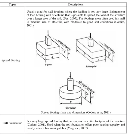
Table 2.2: Types of conventional foundation and its characteristic.
Types Descriptions
Spread Footing
Usually used for wall footings where the loading is not very large. Enlargement of load bearing wall or column that is possible to spread the load of the structure over a larger area of the soil. (Das, 2007). The footings most often used in small to medium size of structure with moderate to good soil conditions (Coduto, 2001).
Spread footing shape and dimension. (Coduto et al, 2011)
Raft Foundation Is a very large spread footing that encompass the entire footprint of the structure (Coduto, 2001). Used when the soil foundation offers poor bearing capacity and mostly when it has weak patches (Varghese, 2007).
Df /b ≤ 1 = Shallow foundation
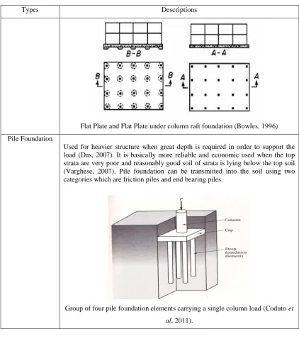
[image:33.595.108.531.312.758.2]Table 2.2: Types of conventional foundation and its characteristic. (continued)
Types Descriptions
Flat Plate and Flat Plate under column raft foundation (Bowles, 1996)
Pile Foundation
Used for heavier structure when great depth is required in order to support the load (Das, 2007). It is basically more reliable and economic used when the top strata are very poor and reasonably good soil of strata is lying below the top soil (Varghese, 2007). Pile foundation can be transmitted into the soil using two categories which are friction piles and end bearing piles.
Group of four pile foundation elements carrying a single column load (Coduto et
al, 2011).
2.4 Shell foundation
Current construction technology has emerged to a new dimension of meeting challenges of problematic ground conditions such as soft soils. In such instances, alternatively shell foundations are now being considered and are cautiously becoming acceptable in the world of design practice.
circumstances. Moreover, some current alternative foundations adopted thin shell structures to optimize the bearing load to weight ratio (q/w) ratio.
2.4.1 The concept of shell structure
Shell structures discover applications in numerous disciplines of engineering. They are pleasing in appearance and economical due to the small thickness of the shell wall. Generally, shell structures are used as roof structures, fluid and solid retaining structures, aerospace structures, etc. The geometry of shell structure is known as unique yet challenging due to curvature in its shape. This curvature is not only attractive in term of aesthetic but also provides good strength.
Adoption of a shell structure as a structural form has given the promise of more advantages. According to Aziz et al. (2011), due to their curved topology, shells generate larger stiffness and strength than corresponding plane surface structural elements. Thus, Huat et al. (2007) refer to shell itself is a material saving as it enables a minimum utilization of material which resulting in a maximum structural advantages yet considered as labor- intensive technique. This may be appropriate in some countries where the economy is characterized by high material-to-labour cost ratios.
2.4.2 Fundamental theory of shell structures
[image:36.595.177.466.258.463.2]The plate (flat) structures served as an instinct for modern shell theories but within these two centuries, shell structures have gained much popularity leaving far behind the application of plate structures. Timoshenko & Krieger, 1959 expressed the derivation of equations 2.1 to 2.2 in the fundamental of shell theory. Figure 2.3 consider an element of δx and δy in x direction under a loading per unit area (q/unit area) which involve stresses.
Figure 2.3: Fundamental theory of shell structures (Timoshenko & Krieger, 1959)
0 x y x q y x y y x y x xy (2.1) Where:
σx, σy = Normal stress in x direction
τxy, τyx = Shear stress
z y x q q
q , , = The component of loading
These will reduce to:
0 x
x
0
y
y yx q x y (2.1b) 0 z
z
qz y zy (2.1c)
Other equation that needs to be satisfied is
0 2 y x 2 2 2 2 2 y z q x z q q y x z y z x z y x z xy
(2.2)
Designs need to be considered in two independent ways and the footing is designed for the worst conditions as shown in Figure 2.4. These two methods are necessitated by the ambiguity in the directions of the earth pressure.
(a) As a uniformly distributed load
[image:37.595.152.241.71.149.2]vertically z load axis. (b) As a uniformly distributed normal to the shell surface.
Figure 2.4: Case for worst condition on footings (Timoshenko & Krieger, 1959)
Since the shell foundation was able to resist and accommodate uniformly distributed load without even causing appreciable distress or any bending effects, it can be suitably used as reinforced concrete footings on very low bearing capacity soils. Furthermore, for a doubly curved shell the effects of moments and shear may be neglected, the membrane theory alone suffices.
[image:37.595.145.492.341.555.2]surface of hyperbolic paraboloid foundation, it is required to have three different axes which are x, y and z axes (3-dimensional equation). The basic equation that satisfies the hyperbolic paraboloid is z kxy. Figure 2.5 clearly shows the relationship between z, x and y axes and h. The equation was then allowed to determine the height and shape of the foundation. Below is the example calculation for the equation:
Table 2.3: Innovative shape foundation and its corresponding geometry equation.
Foundation Geometry equation of foundation
Rectangular hyperbolic paraboloid
shell footing
x; zx = ky
y; zy = kx
[image:38.595.225.441.490.671.2]xy; zxy = k
2.4.3 Types of shell foundation
Shell structures itself have been adopted widely as roofs. Therefore, due to geometric design and the stiffness of the shell element, the adoption of shell design is spread broadly to the foundation. The geometric characteristics of the shell foundation enable them to perform their assigned functions efficiently and effectively in foundations under different circumstances.
However, shell footing is limited to a few geometries and types. Among the shell foundation that can be contributed to the construction field is the cone, funicular, inverted dome, hyperbolic paraboloid, elliptic and folded plate foundations.
The conical shell footing is the simplest form of a shell, which can be employed in foundation engineering due its singly curved surface. The shell may be of uniform thickness, or the same can be made to vary along the slope. However, on account of its circular plan, the use of the conical shell is limited to individual footings. Moreover, due to its circular plan, the use of conical shell footing is restricted to an isolated footing only.
Only a few shells can match the cone in the simplicity of its shape. Reinforced concrete, rotationally symmetric truncated conical footings of the type shown in Figure 2.6 was probably the simplest form in which a shell can be put to use in foundations. The provision of radial and circumferential reinforcement is as simple as for a circular flat footing; while the construction is probably only a little more difficult. It can also serve as the foundation for a tall structure like chimney shaft where it should be in perfect contact with soil throughout its bottom surface and the surcharge that comes on top of it (Chekol, 2009).
[image:39.595.126.520.589.718.2]
(a) Column footing (b) Chimney shaft
For circular or overhead structures like water tanks that supported on a circular row of columns, thin inverted domes considered as alternative to thick circular or annular raft foundations. The transfer of column load to the inverted dome can be effected through a ring beam at top as shown in the Figure 2.7 (Chekol, 2009).
(a) Plan view of spherical dome
[image:40.595.189.448.179.478.2](b) Ovcerhead structures supported on a circular row of columns
Figure 2.7: The inverted spherical dome raft (Chekol, 2009)
columns. It is the success with this form that has given the clue for trying this combination in foundation, where in an upright position they can serve as foundations for columns foot. The hyperbolic paraboloidal shell owes much of its present-day popularity to the pioneering efforts of the famous Mexican engineer architect, Felix Candela. He has demonstrated the construction of hyper footing for the first time for the Mexico City Customs House in 1953. Since then he has poured a large number of such footings in Mexico and elsewhere in Latin America all of which are reported to have performed exceedingly well (Hanna, & Abdel- Rahman, 1990).
(a) Rectangular hyperbolic paraboloid with eccentric column
[image:41.595.189.469.494.618.2](b) Hyperbolic paraboloid bounded by parabola and straight line generator
Figure 2.8: Detail of hyper footing (Hanna, & Abdel- Rahman, 1990)
parabola being curved in same direction. Inverted elliptic paraboloid shell bounded by parabola and edge beam can be used as single unit foundation to support several columns built on the perimeter of the edge beam (Rinaldi, 2012).
(a) Elliptic parabloid
[image:42.595.198.438.149.532.2](b) Elliptic paraboloid raft (single shell)
Figure 2.9: Elliptic paraboloid shell raft (Rinaldi, 2012)
Figure 2.10: Funicular shell footing (Chekol, 2009)
Pyramidal combination of four inclined trapezoidal plate elements has been considered as a subsidiary of folded plate foundation where it can support column at its centre as shows in Figure 2.11. As information, the term pyramidal footing is frequently used for the solid pyramid and used as footing. When this is made hollow one gets the folded plate type of footing described above. Since these pyramidal folded plates can be rendered square or rectangular in plan, they can be combined to form multiple units to serve as combined footings or rafts and serving as a continuous (strip) footing for a continuous load-bearing wall (Kurian, 2006).
(a) Folded plate footing
(b) Folded plate strip footing
[image:43.595.189.455.427.742.2]2.4.4 Critical review of past research
A complete design of foundation consists of two phases; the “geotechnical” and the “structural”. The objective of structural design is to satisfy the structural behavior acting on the foundation – which is flexure and shear. While geotechnical design comprise with characteristics of foundation with a characteristics of soil.
2.4.4.1 Structural performance
The development of shell foundation from conventional flat counterpart or square foundation has emerged to the new dimension in foundation. Nowadays, shell structure types have been chosen due to its advantages.
Esmaili & Hataf (2008) carried out a series of laboratory model experimental tests and numerical studies to investigate the ultimate loading capacities of shell foundations with traditional foundations using conical and pyramidal shell foundations on unreinforced and reinforced sand and compared with circular and square flat foundations. In addition, a new parameter is known as shell factor (SF) was adopted to investigate the effect of foundation configuration on ultimate load and defined in equation 2.3
(2.3)
Where:
a’ : Area of the flat portion of the base of shell and flat foundations (m2) A’ : Base area of counterpart circular and square foundations (m2)
REFERENCES
Al- Azzawi, A. A. (2013). A study of the behavior of shell footings using finite element analysis. Engineering & Technical Journal, 31 A(19), pp. 90-102.
Amy, B. C., and Alan, J. L. (2007). Scale Effects Of Shallow Foundation Bearing Capacity On Granular Material. Lafayette College. United Sates.
Araz, I. and Fitsum, T. (2011). Analysis of Deformations in Soft Clay Due to Unloading. pp.8.
Atkinson, J. (1993). An Introduction to the Mechanics of Soils and Foundations. England: McGraw Hill International (UK) Limited.
Aziz, R. J., Azzawi, A. A. and Al- Ani A. A. (2011). Finite element elastic analysis of hypar shells on winkler foundation. Journal of the Serbian Society for Computational Mechanics, 5 (1), pp. 1-18.
Azzam, W. R. and Nasr, A. M. (2014). Bearing capacity of shell strip footing on the reinforced sand. Journal of Advanced Research, pp. 1-11.
Baban, T. M. (2016). Shallow Foundation: Discussions and Problem Solving. 1st ed. United Kingdom: John Wiley & Sons.
Barnes, G. E. (2000). Soil Mechanics Principles and Practice. 2nd ed. London: Macmillan Press Ltd.
Bowles, J. E. (1996). Foundation Analysis and Design. 5th ed. England: McGraw Hill International (UK) Limited.
Budhu, M. (2008). Foundation and Earth Retaining Structure. United states of America: John Wiley & Sons. Inc. pp. 454.
British Standards Institution. (1990). Classification of soil. London: BS 1377.
Ching, F. D. K. (2008). Building Construction Illustrated. 4 ed. New Jersey. John Wiley & Sons Inc. pp. 2- 33.
Chan, C. M., Wong, P. Y. and Lee, C. C. (2010). Subsidence Control of Construction on Soft Soils with “Akar Foundation”. Modern Applied Science, 4(8), pp. 12 - 23.
Chekol, E. T. (2009). A Study on The Design And Advantage Of Conical Type Shell Foundation Using Analytical And FEM. Addis Ababa University: Ph.D. Thesis.
Coduto, D. P. (2001). Foundation Design: Principles and Practice. 2nd ed. Pearson/Prentice Hall. pp. 143- 434.
Coduto, P. D., Yeung, M. R. And Kitch, W. A. (2011). Geotechnical Engineering Principal and Practices. 3rd ed. New Jersey: Pearson Education Inc. pp. 67-93.
Das, B. M. (2007). Principle of Foundation Engineering, 6th ed, Cengage Publisher. pp. 81-144.
Das, B. M. (2011). Principle of Foundation Engineering. 7th ed, Cengage Publisher. pp. 133-179.
Eberhardt, E., Stead, D., Stimpson, B. and Read, R. S. (1998). Identifying crack initiation and propagation thresholds in brittle rock. Canadian Geotechnical Journal, Vol. 35, pp. 222-233.
Eduard, V. and Theodor, K. (2001). Thin Plates and Shells Theory: Analysis and Applications. New York: Marcel Dekker, Inc.
Elsamee, W. N. A. (2013). An Experimental Study on the Effect of Foundation Depth, Size and Shape on Subgrade Reaction of Cohessionless Soil. Scientific Research Engineering, 5, pp. 785 – 795.
Esmaili, D. and Hataf, N. (2013). Determination of Ultimate Load Capacity of Conical and Pyramidal Shell Foundations Using Dimensional Analysis. Iranian Journal of Science and Technology, Transactions of Civil
Engineering, 37(C+), pp. 423- 435.
Fernando, N., Sendanayake, E., Sendanayake, D., Silva, N. D. (2011). The Experimental Investigation of Failure Mechanism and Bearing Capacity of Different Types of Shallow Foundations. Department of Civil Engineering-University of Moratuwa, pp. 67-72.
Hadmodjo, R. P. ((1991). Cakar Ayam Construction System - Pavement and Foundation System for Structures on Soft Soil, PT Cakar Bumi Consulting Engineers, Jakarta.
Hanna, A. M. and Abdel-Rahman, M. (1998). Experimental investigation of shell foundation on dry sand. ASCE, 116(2), pp. 851–1863.
Hanna, A.M. and Abdel-Rahman, M. (1990). Ultimate bearing capacity of triangular shell footings on sand. Journal of Geotechnical Engineering. Canadian Geotechnical Journal,35(5), pp. 847 .
Head, K. H. (1992). Manual of Soil Laboratory Testing Volume 1: Soil Classification and compaction tests. 2nd ed. Plymouth, England: Pentech Press.
Head, K. H. (1992). Manual of Soil Laboratory Testing Volume 2: PermeabilityShear Strength and Compressibility Tests. Plymouth, England: Pentech Press.
Ho, M. H. (2014). The Potential of Using Cement Rubber Chips and Cement Sand As Additives in Stabilised Soft Clay. Universiti Tun Hussein Onn Malaysia: Ph.D. Thesis.
Huat, B. B. K. and Mohammed, T. A. (2006). Finite Element Study Using FE Code (PLAXIS) on the Geotechnical Behavior of Shell Footings. Journal of Computer Science, 2 (1), pp. 104-108.
Huat, B. B. K., Mohammed, T. A., Abang, A. A. A. A and Abdullah, A. A. (2007). Numerical and Field Study on Triangular Shell Footing For Low Rise Building. International Journal of Engineering and Technology, 4 (2), pp. 194- 204.
Huat, B. B. K., Kazemian, S., Prasad, A. and Barghchi, M. (2011). State of an art review of peat: General perspective. International Journal of the Physical Sciences, 6(8), pp. 1988 - 1996.
Holtz, R. D., Kovacks, W. D. and Sheahan, T. C. (2011). An introduction to Geotechnical Engineering: Prentice-Hall, Upper Saddle River, NJ, pp. 853. John, A. L. M. S. (2014). Development of A New Sand Particle Clustering Method
with Respect To Its Static and Dynamic Morphological and Structural
Jyothi, L. R. and Hashifa, H. P. (2015), Model Test on Bearing Capacity of Conical Shell Strip Footing on Reinforced Clay. International Journal of Innovative Research in Science, Engineering and Technology, 4 (10), pp. 10291 – 10297.
Kim, N. R. and Kim, D. S. (2011). The Role of Physical Modeling in the Design of Geotechnical Systems. First International Workshop on Design in Civil and Environmental Engineering. pp 11-17.
Kulkarni, M. S. and Aliasgher, L. (2014). Analysis of Tensile Fabric Structure Using Thin Concrete Doubly Curved Shell. International Journal of Research in Advent Technology, 2 (3), pp.156-165.
Kurian, N. P. (1993). Performance of Shell Foundation on Soft Soil. Proceedings of the International Conference on Soft Soil Engineering, pp.383-392.
Kurian, N. P. (1995). Parametric Studies on the Behaviour of Conical Shell Foundations. Proceedings V East Asia-Pacific Conference on Structural Engineering and Construction, pp. 1733-1738.
Kurian, N. P. (2006). Shell Foundation: Geometry, Analysis, Design and Construction, Alpha Science International Ltd. pp. 1-566.
Kurian, N. P. and Jeyachandran, S. R. (1972). Model Studies on the Behaviour of Sand Under Two and Three Dimensional Foundation. India Geotech Journal, 11(1), pp. 79-90.
Kurian, N. P. and Devaki, V. M. J. (2005). Analytical Studies on the Geotechnical Performance of Shell Foundation. NCR Research press website at http://cginrc.ca.
Lamb, T. W. and Whitman, R. V. (1969). Soil Mechanics. New York: John Wiley and Sons.
Lim, S. M. (2015). Effect of Differently Stabilised Lateritic Soils on Its Geotechnical Properties and Dust Generations. Universiti Tun Hussein Onn Malaysia: Ph.D. Thesis.
Maharaj, D. K., Chandana, D. and Madhuri, S. (2004). Finite Element Analysis of Strip Type Shell Foundation and its Interaction. Electronic Journal of Geotechnical Engineering, pp. 1-7.
Mitchell, J. K., and Soga, K. (2005). Fundamentals of Soil Behavior: Hoboken, NJ: John Wiley & Sons Inc. pp. 592.
Oguz, A. D and Ahmet, B. (2010). A Study on Soil-Structure Interaction Analysis in Canyon-Shaped Topographies. 35(3). pp. 255– 277.
Ornek, M., Demir A, Yildiz, A. and Laman, M. (2012), Numerical Analysis of Circular Footings on Natural Clay Stabilized With A Granular Fill. pp 61-75. Parsons, J. D. (1936). Progress Report on an Investigation of the Shearing Resistance of Cohesionless Soils. Proceedings of the 1st International Conference on Soil Mechanics and Foundation Engineering. Vol. 2, pp. 133-138.
Patra, C. R., Das, B. M. and Atalar, C. (2016). Bearing Capacity of Embedded Strip Foundation on Geogrid-Reinforced Sand (Unpublished).
Philippe, G. C and Cristinel, M. (2005). An Introduction to Shell Theory. Springer-Verlag. pp 2-69.
Prasad, B. D., Hariprasad, C. and Umashankar, B. (2014). Shear Strength Envelope of is Sand under Various Confining Pressures. Proceedings of Indian Geotechnical Conference, pp. 123-127.
Punmia, B. C., Jain, A. K, and Jain, A. K. (2005). Soil Mechanic and Foundation, 16th Edition, Laxmi Publications (P) Ltd, pp. 639-767.
Rinaldi, R. (2012). Inverted Shell Foundation Performance In Soil. Concordia University: Ph. D. Thesis.
Retrieved from http://www.merriamwebster.com/dictionary/biomimetics.
Salunkhe, M., Yadav, M., Pal, S., Patti, S. and Mhatre, V. (2016). Conical and Hyperbolic Paraboloid Shell Foundation. International Journal on Recent and Innovation Trends in Computing and Communicatio, pp. 310 – 312. Sabariah, M., Ismail, I., Zarina, M. A, Mas, R., Nur, A. M. A and Ili, I. A. (2009).
The Emphasis for Hydrostatic Pressure in Soft Soil Area. International Conference on Sustainable Infrastructure and Built Environment in
Developing Countries, pp. 103 – 107.
Sivakugan, N. and Das, B. M. (2010). Geotechnical Engineering: A Practical Problem Solving Approach. J. Ross Publishing Series. pp. 1-357.
Layered Sand. International Journal of Advanced Engineering Technology. pp. 192 -196.
Thermann, K., Gau, C. and Tiedemann, J. (2006). Shear strength parameters from direct shear tests - influencing factors and their significance. IAEG, pp. 484. Thilakan, S. and Naik, N. (2015). Geotechnical behaviour of shell foundations. 50th
Indian Geotechnical Conference, pp. 1 – 9.
Timoshenko, S. and Krieger, S. W. (1959). Theory of Plates and Shells. India :McCraw-Hill Education Pvt Limited. pp. 1-590.
Tileylioglu, S., Nigbor, R. L. and Stewart, J. P. (2013). Determination of Soil-Structure Interaction Effects for a Model Test Structure Using Parametric System Identification Procedures. pp. 1 -10.
Tuladhar, R., Maki, T., Mutsuyoshi, H. (2008). Cyclic behavior of laterally loaded concrete piles embedded into cohesive soil, Earthquake Engineering & Structural Dynamics, 37 (1), pp. 43-59
Varghese, P. C. (2007). Foundation Engineering. New Delhi: PHI Learning Private Limited. pp. 109-133.
Ventsel, E. and Krauthammer, T. (2001). Thin Plates and Shells: Theory, Analysis, and Applications. Marcel Dekker Inc. New York. pp. 298-307.
Venkatramaiah, C. (2006). Geotechnical Engineering. 3rd ed. New Delhi: New Eye International Publisher (P) Limited. pp. 607-620.