DEVELOPMENT AND CHARACTERIZATION OF THE IONIC POLYMER METAL COMPOSITE ACTUATED CONTRACTILE WATER JET
THRUSTER
by
MUHAMMAD FARID BIN SHAARI
Thesis submitted in fulfilment of the requirements for the degree
of Doctor of Philosophy
ACKNOWLEDGEMENTS
First of all I would like to express my gratefulness to Allah the Almighty which make me able to finish this project successfully. I would like to dedicate my sincere gratitude and thankful to my supervisor, Associate Professor Dr. Zahurin bin Samad who had supervised me along this time. His passions, guidance and continuous support for this project had led to the accomplishment of my studies. His efforts are muchly appreciated. Secondly, I would like to thank all the supporting staffs, Mr. Norijas Abd. Aziz, Mr. Mohd Ali Shabana Mohd Raus, Mr. Mohd Ashamuddin Hashim, Mr. Hashim Md. Nordin and Mr. Rosnin Saranor who had guided me in dealing with technical stuffs as well as procurement process as well as to all my colleagues; Dr. Cham Chin Long, Mr. Muhammad Alif Rosly, Mr. Muhammad Husaini Abu Bakar, Mr. Lim Chong Hooi and Mr. Ameer Mohamed Abdeel Aziz Mohamed Hanafee who had spent time together in sharing the knowledge and finding the solutions.
TABLE OF CONTENTS
Page
ACKNOWLEDGEMENTS ii
TABLE OF CONTENTS iii
LIST OF TABLES vii
LIST OF FIGURES viii
LIST OF ABBREVIATION xiii
LIST OF SYMBOLS xv
ABSTRAK xviii
ABSTRACT xix
CHAPTER ONE: INTRODUCTION
1.1 Background 1
1.2 Problem Statement 5
1.3 Objectives 7
1.4 Scope of Work 7
1.5 Organization of Thesis 8
CHAPTER TWO: LITERATURE REVIEW
2.1 Squid mantle morphology and propulsion system 9
2.2 AUV propulsion system 13
2.3 CWJT 18
2.3.1 Contraction frequency 19
2.3.2 Thrust and drag 20
2.3.3 Dimensionless parameter 24
2.3.4 Previous works on CWJT 26
2.4 Smart material actuators 34
2.5.1 Factors that influence IPMC performance 43
2.5.2 Overview on IPMC actuator fabrication 46
2.5.3 Overview on IPMC actuator characterization 48
2.6 Summary of literature review 50
CHAPTER THREE: METHODOLOGY
3.1 IPMC actuator development 52
3.1.1 IPMC fabrication 52
3.1.2 IPMC actuator characterization 58
3.2 CWJT prototype design 65
3.2.1 Conceptual design 66
3.2.2 CWJT mantle model determination 68
3.2.3 Drag experimental procedure 75
3.2.4 Drag simulation procedure 76
3.2.5 CWJT detail design 81
3.3 CWJT prototype fabrication 83
3.4 Ejected fluid flow simulation 85
3.5 CWJT contraction measurement 88
3.5.1 Volume differentiation measurement procedure 89
3.5.2 Volume contraction calculation 91
3.6 Empirical thrust measurement 94
3.6.1 Experimental setup 94
3.6.2 Experiment procedure 96
CHAPTER FOUR: RESULTS AND DISCUSSION
4.1 IPMC actuator characterization result 100
4.1.1 IPMC actuator force characterization results 100 4.1.2 IPMC actuator’s oscillation characterization results 105
4.2 CWJT Prototype Design 107
4.2.1 CWJT model 107
4.2.2 Drag analysis 109
4.3 Fluid flow simulation analysis 113
4.3.1 Pressure distribution 116
4.3.2 Velocity distribution 120
4.3.3 Generated thrust 125
4.4 CWJT contraction analysis 126
Contraction displacement 127
4.4.2 Contraction volume 132
4.5 Empirical thrust measurement 135
4.5.1 Water jet velocity measurement 135
4.5.2 Water jet thrust 138
CHAPTER FIVE: CONCLUSION AND RECOMMENDATION
5.1 Research conclusion 143
5.2 Research contribution 146
5.3 Recommendation and future works 147
REFERENCES 149
APPENDICES
Appendix A: Nafion specification
Appendix C: AUV orthographic drawing Appendix D: CWJT Drawings
Appendix E: AUV velocity and shear wall stress simulation
Appendix F: Water jet dynamic pressure and total pressure simulation Appendix G: Water jet velocity contour simulation
Appendix H: Water jet velocity vector simulation Appendix I: Arduino programming code
LIST OF TABLES
Page
Table 2.1 Previous research on the CWJT 31
Table 2.2 Classification of smart material actuators 35 Table 2.3 Characteristics of actuators and its definition 38 Table 2.4 The displacement and driving force of IPMC at different DC 44
supply voltages of 1V-3V (Chung et al., 2006)
Table 3.1 LDPE properties (Plasticintl, 2016) 71
Table 3.2 Mesh models for mantle model grid independency test 73 Table 3.3 Mesh models for AUV drag grid independency test 79
Table 3.4 Control Parameters and AUV Dimension 81 Table 3.5 Mechanical Properties for EVA copolymer 84
Table 3.6 Mesh models for fluid velocity grid independency test 86 Table 3.7 Actuation frequency 91
Table 4.1 DOE analysis to verify the most influential factors on the 108
displacement the IPMC actuator during oscillation Table 4.2 Simulation results for all design models 110
Table 4.3 Averaging the contraction displacement highest (frequency) 128
Table 4.4 Averaging the contraction displacement (lowest frequency) 129
Table 4.5 Compilation of averaged data for every frequency and 129
nozzle aperture diameter Table 4.6 Angle for every contraction in radian 133
Table 4.7 Contraction volume of for every samples 134
LIST OF FIGURES
Page
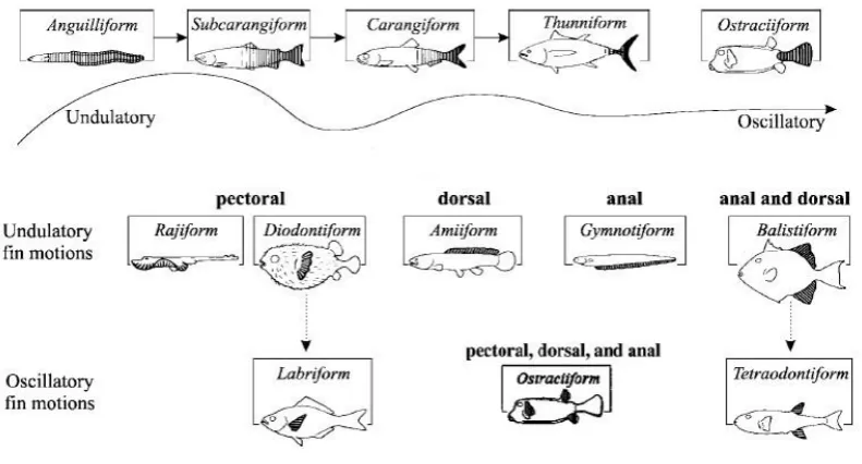
Figure 1.1 Classification of Swimming Mechanism 3
(Colgate and Lynch, 2004)
Figure 2.1 Squid morphology (Krieg and Mohseni, 2010) 10 Figure 2.2 Squid mantle muscles and its structure (Gosline and 10
De Mont, 1985)
Figure 2.3 a) The parallel lines present squid radial muscle and 11 (b) SEM image of complex collagen fibres in squid mantle
Figure 2.4 Contractile phases of the squid mantle (Gosline and 12 De Mont, 1985)
Figure 2.5 Variation of commercial thrusters. From left, open rotary 14 propeller blade on the right is the water jet thruster
Figure 2.6 Some examples of AUV thrusters (Lin and Guo, 2012; 15 Gonzalez, 2004. (a) Centrifugal thrusters with nozzle,
(b) rotary blade propeller
Figure 2.7 Underwater vehicle or robot propulsion system 16 classification.
Figure 2.8 Examples of bio-inspired propulsion system; Robosquid 17 (Krueger et al., 2010) and Vortex ring thruster (Krieg and
Mohseni, 2009)
Figure 2.9 Fundamental concept of the contractile water jet propulsion; 19 (a) Relax phase, (b) Inflation phase and (c) Deflation phase
Figure 2.11 Bollard Pull Test (Muljowidodo et al., 2009); a) Schematic 23 diagram b) Actual test
Figure 2.12 Thrust measurement using gage test (Guo et al., 2010) 24 Figure 2.13 Vortex ring formation based on formation number (Gharib 26
et al., 1998); a) L/D = 2, b) L/D = 3.8 and c) L/D = 14.5
Figure 2.14 Speed per body length performance of several underwater 27 biomimetic propulsion system (Chu et al., 2012)
Figure 2.15 Comparison of CWJT locomotion speed performance with other 29 propulsion systems and its natural counterparts (Chu et al., 2012) Figure 2.16 Work capacity of smart material actuators according to their 39
weight (Zupan et al., 2002)
Figure 2.17 Basic IPMC actuator structure 41
Figure 2.18 Nafion (perflorinated alkene) monomer 41
Figure 2.19 IPMC actuation phase (Punning et al., 2007); (a) IPMC without 42 voltage supply, (b) IPMC with voltage supply
Figure 2.20 IPMC model (Shahinpoor and Kim, 2001) 43 Figure 2.21 IPMC actuation free body diagram (Ji et al., 2009) 44 Figure 2.22 Designation of every dimension for IPMC actuator (Ji et al., 46
2009)
Figure 2.23 IPMC displacement at different thickness and supply voltage 47 (Kim et al., 2003)
Figure 2.24 IPMC tip force at different thickness and supply voltage 47 (Kim et al., 2003)
Figure 3.1 Primary process to fabricate the IPMC (Yu et al., 2007; 54 Yip et al., 2011)
Figure 3.2 Platinum salt hydrate ([Pt(NH3)4]Cl2) 55
Figure 3.3 Reduction process in water bath 55
Figure 3.4 Flow chart for the secondary process (Yu et al., 2007; 57 Yip et al., 2011)
Figure 3.5 Platinum particles formed on the Nafion surface during 58 reduction process and became grey coloured IPMC
Figure 3.6 Pictorial view of the actuating force characterization 61 Figure 3.7 Schematic of actuation force characterization 61 Figure 3.8 Oscillation characterization with illustrated laser beam for 63
displacement measurement.
Figure 3.9 Schematic of oscillating characterization 64
Figure 3.10 AUV Prototype with CWJT Thruster 66
Figure 3.11 Real squid mantle 67
Figure 3.12 Conceptual design of the proposed CWJT 67
Figure 3.13 Force elements during contraction 69
Figure 3.14 Proposed CWJT mantle designs 70
Figure 3.15 Flow chart for the simulation analysis 72 Figure 3.16 Definition of the fixed support area and the deformable area 74
of the model at specific actuation force magnitude
Figure 3.17 AUV rapid prototype for drag test 75
Figure 3.18 Drag testing experimental setup 76
Figure 3.19 Simulation process flow for ANSYS Fluent software 78
Figure 3.21 Meshed domain 80 Figure 3.22 Setting the boundary condition in ANSYS Fluent 81
Figure 3.23 Design of the mould for CWJT mantle 85
Figure 3.24 Geometrical model of the simulation 87 Figure 3.25 Example of calculation and converged solution 88 Figure 3.26 Experimental setup for contraction measurement 90 Figure 3.27 Actual contraction measurement 90 Figure 3.28 3D view of the contraction volume of the CWJT 92 Figure 3.29 Area division to determine the volume by integration 93 Figure 3.30 Experimental setup schematic diagram 95 Figure 3.31 Actual setup test rig 95
Figure 3.32 Ejection time, te calculation 98
Figure 4.1 Supply voltage influence on actuation the force characterization 101
Figure 4.2 Metal plated influence on the actuation force characterization 102
Figure 4.3 IPMC actuator force characterization at different thickness 104
Figure 4.4 IPMC actuator force characterization at different length 105
and orientation of actuation Figure 4.5 Displacement of IPMC actuator at different length and 107
input frequency Figure 4.6 Grid independency test for the CWJT mantle model 110
Figure 4.7 Grid independency test for shear wall stress of the AUV 111
Figure 4.8 Drag analysis via simulation and experiment 113
Figure 4.9 Drag contour based on fluid flow velocity 114
Figure 4.10 Grid independency test for fluid flow analysis 115
Static Pressure at various nozzle aperture
Figure 4.12 Dynamic pressure distribution in the nozzle and at the opening 119
Figure 4.13 Total pressure distribution within the nozzle and at the opening 119
Figure 4.14 Dynamic and total pressure for different nozzle aperture 120
diameter at 10 mm water jet trail Figure 4.15 Fluid velocity analysis using ANSYS FLUENT software 121
Figure 4.16 Vector analysis on fluid flow 122
Figure 4.17 Relation between fluid velocity and the nozzle aperture 125
diameter Figure 4.18 Thrust at different nozzle aperture size by simulation result 126
Figure 4.19 Acquisition of raw data for the highest actuation frequency, 127
0.5 Hz Figure 4.20 Acquisition of raw data for the lowest actuation frequency, 128
0.005 Hz Figure 4.21 The correlation between displacement and actuation 130
frequency at different nozzle apertures Figure 4.22 Determination of affected zone to measure the maximum 132
contraction volume Figure 4.23 Contraction volume at different actuation frequency 135
Figure 4.24 Fluid ejection during contraction 136
Figure 4.25 Measurement of the water jet velocity 136
Figure 4.26 Water jet velocity and the nozzle aperture sizes 137
Figure 4.27 Thrust at different nozzle aperture 139
LIST OF ABBREVIATIONS
AC Alternating current ANOVA Analysis of Variance
ASTM American Society for Testing and Materials AUV Autonomous Underwater Vehicle
BCA-O Body/Caudal Actuation-Oscillatory BCA-U Body/Caudal Actuation-Undulatory CAD Computer Aided Design
CFD Computational Fluid Dynamic CNT Carbon nanotube
CP Conductive polymer
CWJT Contractile water jet thruster DAQ Data acquisition
DC Direct current DE Dielectric elastomer
DI Deionized water
DOE Design of Experiment DOF Degree of Freedom
DPIV Digital Particle Image Velocimetry EAP Electro active polymer
EVA Ethylene Vinyl Acetate
EW Equivalent weight
FDM Fused Deposition Modelling FEA Finite Element Analysis
IPMC Ionic Polymer Metal Composite JET Water jet propulsion
MPA-O Median/Paired Actuation-Undulatory MPA-U Median/Paired Actuation-Oscillatory PTFE Polytetrafluoroethylene
LIST OF SYMBOLS
t V
Volume changes in time
µ Dynamic viscosity of the fluid AAUV Fluid-AUV contact area
Ac Contact area of the actuator on the CWJT
An Nozzle aperture
BL/s Speed unit in Body-Length per second CD Drag coefficient
CT Capacitive ion transduction
Dn Nozzle diameter
E Young Modulus
eq Ion exchange capacity
EW Equivalent weight
Ɛ0 Lever deformation
FB Blocking force
Fb Reaction force from the body of the CWJT
fc Contraction frequency
Fc Contraction/Actuation force
FD Drag force
fi Input frequency
Fwj Reaction force from the contraction
Hz Frequency unit, Hertz
h IPMC thickness
I Second moment inertia
L IPMC actuator length L/D Length over diameter ratio
Le Maximum distance of the ejected fluid
Ll Length of the force to the strain gage
Ln Length of the nozzle channel
me Ejected fluid mass
ṁe Mass flow rate of the ejected fluid
mi Initial fluid mass
p Distributed load of the IPMC
Pact Actuation pressure (Applied pressure by IPMC on CWJT)
Pc Contraction pressure (inside CWJT)
Ps Static pressure
PT Total pressure
q Dynamic pressure
Q Fluid volumetric flowrate
Re Reynolds number
Rh Hydrodynamic resistance
Rn Nozzle radius
Rp Resistance across the Nafion
Rs Resistance between electrode and Nafion
Rss Surface resistance of the IPMC
S IPMC actuator bending displacement
Smax Maximum IPMC actuator bending displacement
te Time taken to reach the maximum distance of the ejected fluid
Tf Thrust
ub AUV velocity
uj Average jet velocity
Vc Contraction volume or ejected fluid volume (mm3) at certain time
Vs Supply voltage (v)
Vmax Maximum contraction volume (mm3)
V
f Contraction volume ratevAUV AUV velocity
ve Ejected fluid velocity
vi Initial fluid velocity
vk Kinematic viscosity of water
vosc Oscillation speed
W Width of the contraction volume w Width of IPMC actuator
Z Moment second area
Zw Nafion induction
α IPMC actuator bending angle β CWJT contraction angle δ CWJT mantle displacement
ΔP Pressure drop
π pi (3.142)
ρf Fluid density
ρw Water density
PEMBANGUNAN DAN PENCIRIAN PENUJAH JET AIR MENGECUT GERAKAN KOMPOSIT POLIMER – LOGAM BERION
ABSTRAK
DEVELOPMENT AND CHARACTERIZATION OF THE IONIC POLYMER METAL COMPOSITE ACTUATED CONTRACTILE WATER JET
THRUSTER
ABSTRACT
CHAPTER ONE INTRODUCTION
Background
The development of autonomous underwater vehicle (AUV) is simply driven by three major lines of motivation; the underwater biodiversity exploration, environmental ecology concern and the current fast growing sub-ocean industry (Yuh, 2000b; Roper et al., 2010). The related task that requires AUV service regarding these domain of activities including underwater research, oil and gas exploration, underwater construction, water quality monitoring, military activities, sub-ocean mining and eco-tourism. The working environment and nature of the task has determined the design of the AUV. For instance, a linear motion seabed topography scanning requires a torpedo shape AUV design for minimal drag influence. On the other hand, three dimensional seabed pipeline monitoring would utilize a 6 Degree of Freedom (DOF) box shaped AUV design because it has more manoeuvrability and linear speed locomotion is not a priority (Guo et al., 2010; Shi et al., 2013). Meanwhile, Yue et al. (2015) and Guo et al. (2016) had designed and developed a spherical AUV which has the advantage in manoeuvrability, flexibility and outstanding shock resistance.
investigation (Vasilescu et al., 2005; Campos and Codina, 2015). However, though the AUV technology had been developed since 1960’s, researchers and engineers are still struggling to achieve the ultimate swimming performance under the conventional design AUV which is trading off the speed and manoeuvrability of the AUV (Roper et al., 2010). Furthermore, for a small scale sensing AUV which has limited space for energy supply means shortage of operation time. Another concern is the noise from the conventional electric motor is unnecessary. All these constraints had shifted the researchers to the out-of-the-box solution; by getting the inspiration from the nature for design outcome and promoting new actuation techniques (Shi et al., 2013).
Naturally, aquatic animals such as fish, squid and eels are excellent swimmers with high propulsion efficiency in term of both speed and manoeuvrability (Yu et al., 2005). Without rotating propeller, fish for instance manages to move at fast speed (up to 65mph for sailfish) and able to accelerate at difficult angle either to catching its prey or escaping away from its predators (Hingham, 2007). Besides, those aquatic animals manage to move in near silent motion. Ability to move stealthily is a vital characteristic for predator fish. In order to achieve the optimum propulsion efficiency at high manoeuvrability degree and lower drag, researchers had imitated these aquatic animal swimming principles in their AUV design (Chu et al., 2012). This non conventional AUV is known as bio-inspired or biomimetic AUV. In general, there are three main classifications for aquatic animal swimming mechanism which are;
i. Oscillating ii. Undulatory iii. Jet propulsion
Almost all aquatic vertebrates such as fish, eels and quite large number of reptile species such as snake, crocodile and iguana utilize oscillating and undulatory swimming mechanics. Only few invertebrates such as squid, jellyfish, octopus and nautilus apply the water jet locomotion. Unlike the oscillating and undulatory swimming mechanism, the water jet propulsion is based on impulse.
Figure 1.1: Classification of Swimming Mechanism (Colgate and Lynch, 2004)
electric motor itself, contribute unnecessary load. Body contraction water jet which is applied by the squid, compresses the fluid by reducing the mantle volume. This contraction is not a continuous process but it is an intermittent process. Thus, the contraction frequency has significant influence on the thrust efficiency. There are few option of actuators that can be utilized to perform the intermittent contraction. In addition to the contraction frequency, contraction force, water inlet and water outlet opening are another few parameters that must be considered to achieve the optimum thrust efficiency.
Hence, in this research the main goal is to developed contractile water jet thruster (CWJT) and conduct parametrical studies to investigate its performance as a thruster for small AUV. A suitable actuator which is more silent, light and compatible to the sensing measurement condition will be adapted. Based on preliminary studies, there are few options of actuators that could be utilized to substitute the fluid compression techniques which is driven by blade – motor integration. The potential actuators would be pneumatic based actuators and smart material actuators. Though the air is compressible and the actuators could be miniaturized, a complete pneumatic system require air reservoir, compressor and control valve which are too bulky for small scale AUV (Nishioka et al., 2011). Smart material actuators seems likely to fit in the actuation system. However, there are numbers of smart materials with various actuation characteristics and input requirements (Mikhrafai et al., 2007).
materials, which are metal based, ceramic based and polymer based. Shape Memory Alloys (SMA) is one example for metal based smart material and piezoelectric material is a kind of ceramic based smart material. Dielectric elastomer (DE), Conducting Polymers and Ionic Polymer Metal Composite (IPMC) are few examples for polymer based smart materials. Based on the requirement, IPMC had been selected as the potential actuator for the CWJT. IPMC requires low driving voltage, flexible and able to work underwater (Shahinpoor and Kim, 2001). However, the main challenge for this research is mainly comes from the limitation of IPMC whereby the actuation force is between 1.0 gf and 8.0 gf per actuator, depending on the dimensional geometry (Shahinpoor and Kim, 2001). The research works would involve the design and development of CWJT using smart material actuator and investigating the water jet generation performance at different inputs.
Problem Statement
the AUV, it limits the flexibility and locomotion speed of the AUV. The flexibility features is vital for AUV in challenging task such as monitoring and logging data in a complex underwater structure (Xu and Mohseni, 2012). Too much thrusters attached to the AUV make it rigid and bulky. Hence, it difficult to pass through narrow passage or staggered corners. This bulky shape AUV will also decreasing its locomotion speed by increasing the drag.
Another problem with the existing rotary blade thruster is the noise that being created by the blade and electric motor vibration. As water is denser than air, then any vibration that caused by the thruster and electric motor will be propagated in all direction from the AUV. The noise from this vibration must be avoided for certain underwater mission especially that require highly sensitive sensing measurement. Those noise will interrupt the data logging process as well as giving effect to the surrounding objects. Besides, there is another problem with rotary blade thruster which is getting entangled with debris or long rope – like objects such as drifted wires, plastics, net, ropes or even long kelps. Marine and river pollution had increased drastically over last few decades especially involving with plastics (Ivar do Sul and Costa, 2014; Cole et al., 2011; Desforges et al., 2014). Hence, based on these problems, a novel design of underwater thruster without using rotary blade propeller will be developed. Fluid displacement that produces thrust from the rotary blade propeller will be performed using another technique. In this research, the feasibility studies of the new technique will be conducted.
Objectives
The main objective of this research is to investigate the performance of the IPMC actuated CWJT thruster. This main objective consists of few specific objectives which are to;
1. Characterize the IPMC actuation force and bending displacement over few input elements such as voltage, frequency, IPMC length and IPMC thickness. 2. Utilize the IPMC actuation force and bending displacement for generating
CWJT prototype.
3. Investigate the influence of nozzle aperture size, input frequency and supply voltage on the thrust force generation.
Scope of Work
viscosity of non-Newtonian fluid will be used. The ambient pressure of the working environment will be fixed at the atmospheric pressure which is approximately 101.39 kPa. This is because the developed AUV will be applied in shallow water where there is no extreme depth working dimension.
Organization of Thesis
This thesis is organized into five chapters. Chapter 1 gives the background of the research including the main goal and motivation of this research. The problem statement, objectives and scope of the studies are also described in this chapter. The content in Chapter 2 provides reader with the review on the current researches on biomimetic underwater robot propulsion systems. This review covers the various design and types of the contractile water jet thrusters, the selection of actuators and the introduction of IPMC smart actuator as well as brief review on the structure of real squid mantle.
CHAPTER TWO LITERATURE REVIEW
This chapter reviews the squid mantle morphology and its locomotion system, the autonomous underwater propulsion systems, the CWJT, water jet mechanics and the IPMC actuator. The overview of the autonomous underwater propulsion system covers the design aspects, working principle, types of actuators and the future trend of the propulsion system.
2.1 Squid Mantle Morphology and Propulsion System
Figure 2.1: Squid morphology (Krieg and Mohseni, 2010)
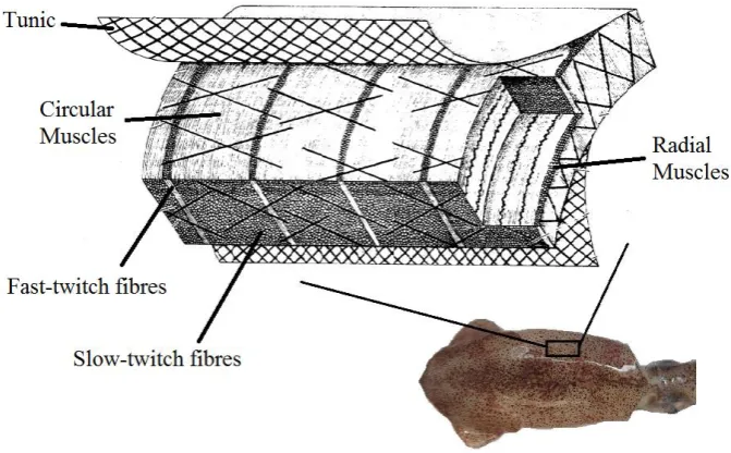
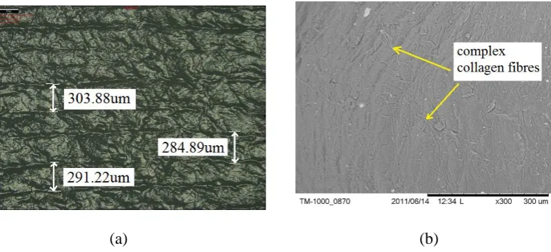
For instance, octopus and cuttlefish have more rounded shape edge. There are two types of muscles that form the squid mantle. They are the radial muscle and circular muscle (Gosline and De Mont, 1985). The structure of these muscles is depicted as in Figure 2.2. Between these muscles, lies another two types of collagen fibres that help actuation of every muscle in every contractile phase. Figure 2.3 a) and b) show the real muscles of squid mantle, viewed using Alicona 3D profile microscope and Scanning Electron Microscope (SEM).
[image:29.595.144.480.492.700.2][image:30.595.120.520.70.253.2]
(a) (b)
Figure 2.3: a) The parallel lines present squid radial muscle and (b) SEM image of complex collagen fibres in squid mantle
At this stage, the circular muscle contracts while the radial muscle relaxes to increase the mantle thickness and reducing the internal volume. The internal diameter reduced to 40 % from its initial value. Research had recorded that the contraction pressure in the mantle would reach up to 25 kPa, 36 % higher than normal human systolic blood pressure (Gosline and De Mont, 1985). The sudden volume reduction ejects the fluid out via muscle controlled nozzle area. Then, the mantle returns to its inflation stage. Figure 2.4 exhibits the cycle of this contractile phase. This process cycles continuously for nonstop locomotion. The speed of the locomotion is controlled by the contraction force and the nozzle opening area. Understanding the basic principle of this squid mantle working behaviour is more less would benefit to preliminary concept to design the CWJT AUV.
2.2 AUV Propulsion System
Propulsion system refers to a mechanism that converts mechanical power to generate the driving force that could move a body. In the case of underwater robot or vehicle, propulsion system is an essential element and becomes an indispensable factor in designing any underwater vehicle (Alotta et al., 2014). Lin et al. (2012) in his research revealed that the propulsion system is the basis of the control layers of the whole system for the autonomous underwater vehicle. In addition, the propulsion system is also the main energy consumer compared to other system in underwater robot (Aras et al., 2009). Besides, for autonomous underwater vehicle where the energy capacity is limited, the applied propulsion system must be efficient to cover wider and last long operation range (Roper et al., 2011).
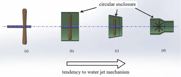
Most AUV applies rotary blade propeller which is driven by electric motor as the actuator.
[image:33.595.128.512.485.649.2]Ironically, the existing commercial rotary blade thrusters applies the water jet principles but in different fluid compression technique. Starting at lower than 200mm blade diameter, the thrust efficiency of the rotary blade propeller declines significantly (Schultz, 2009). Thus, engineers had designed the rotary blade thruster with hole-through cylindrical shape enclosure to increase the thrust efficiency. The enclosure varies in term of radial convergence degree, enclosure length and inlet-outlet diameter ratio. As concluded in Figure 2.5, this variation has led the ‘open’ rotary blade propeller to the design of commercial water jet thruster. Generally, once a smaller size of underwater vehicle is being developed, then the water jet thruster has the tendency to be applied. There are many variations of rotary blade propeller design. Some of them work with nozzle, some without nozzle and another type is using centrifugal wheel mechanism with nozzle (Figure 2.6).
[image:34.595.138.513.69.263.2]
(a) (b)
Figure 2.6: Some examples of AUV thrusters (Lin and Guo, 2012; Gonzalez, 2004); (a) Centrifugal thrusters with nozzle, (b) rotary blade propeller
The biomimetic propulsion examples are such as the oscillating caudal fin and jellyfish water jet propulsion (Xu et al., 2008; Yeom and Oh, 2009). These biomimetic propulsion systems had been applied for AUV locomotion, especially in a small scale prototype as an alternative option of the common rotary blade propeller. The reasons why biomimetic propulsion had been adapted are to increase the propulsion efficiency, to save energy, to improve manoeuvrability, to operate in shallow water, to operate silently and to be robust against messy water (Xu et al., 2007).
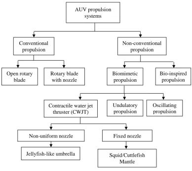
Figure 2.7: Underwater vehicle or robot propulsion system classification
AUV propulsion systems
Fixed nozzle
Bio-inspired propulsion Non-conventional
propulsion
Biomimetic propulsion Conventional
propulsion
Open rotary blade
Rotary blade with nozzle
Jellyfish-like umbrella Squid/Cuttlefish
Mantle Non-uniform nozzle
Contractile water jet thruster (CWJT)
Oscillating propulsion Undulatory
[image:36.595.119.481.68.231.2]
(a) (b)
Figure 2.8: Examples of bio-inspired propulsion system; (a) Robosquid (Krueger et al., 2010) and Vortex ring thruster (Krieg and Mohseni, 2009)
2.3 CWJT
As discussed in the final part of Section 2.2, biomimetic water jet propulsion is inspired by mimicking the squid and jellyfish jet propulsion system. Contractile function of the pressure chamber is the notably character to show the biomimetic propulsion system. Currently there are two categories of CWJT which are the non uniform nozzle size or aperture and uniform or fixed nozzle size CWJT. Biomimetic jellyfish is an example for CWJT that has non uniform nozzle (Marut et al., 2013; Barber et al., 2011) while the biomimetic cuttlefish is an example of uniform nozzle CWJT (Wang et al., 2011). CWJT which is developed in this research falls under the uniform nozzle CWJT category. It is well understood that the fundamental water jet thruster design consists of pressure chamber, actuator, water inlet and nozzle as the water outlet (Figure 2.9). Each of these components has big influence on the performance of the generated pulsed water jet. In fact, all these components are interrelated each other. For instance, the volume of the pressure chamber determines the amount of fluid to produce the thrust. Pressure chamber volume differentiation depends on the speed and force of the actuator. On the other hand, nozzle opening area and the actuator would determine the velocity of the ejected fluid.
This process is recognized as deflation process. The compressed fluid will be ejected via the nozzle (Figure 2.9). This process repeats in several cycles for continuous motion. The continuous cycles are one of the vital observation in developing a CWJT. It is measured in term of the contraction frequency.
Figure 2.9: Fundamental concept of the contractile water jet propulsion; (a) Relax phase, (b) Inflation phase and (c) Deflation phase
2.3.1 Contraction frequency
Repeating and continuous contraction creates sine wave data for physical properties of the CWJT such as the volume and pressure differentiation, contraction force, ejected fluid velocity as well as thrust for every pulse. As described in Section 2.3, fluid manipulation at certain rate determines the performance of the CWJT. Thus, fluid volume and contractile frequency are among the significant factors that influence the performance of the CWJT. The relation between the fluid volume and the contraction frequency can be represented as a sine function and described in equation 2.1 (Stemme and Stemme, 1993):
)
2
sin(
)
(
max c cc
t
V
f
t
V
(2.1)Pressure
chamber Nozzle
Inlet
Fluid in
Water jet
Actuator’s motion
where Vc is the volume of the ejected fluid at specific time, tc. Vmax is the maximum
ejected fluid volume which is depending on the maximum expansion of the pressure chamber. The maximum ejected fluid volume could be translated as the amplitude in the typical sine function. fc is the contraction frequency. Due to the above relation, the
sine function gives the positive and negative fluid volume. However, it is impossible to have negative volume. Thus, shifted sine function had been used to model the contractile pressure chamber volume as shown in Equation 2.2;
c c c
c t V f t V
V ( ) maxsin(2
) (2.2)During inflation phase, the amount of the ingested fluid should be equal to Vmax
ideally. During total deflation, Vmax is equal to zero. This condition however, depends
on the contraction frequency and speed of actuation. In this research, Vc variation will
be observed by varying the fc values. Conclusion on the hypothesis will be obtained to
show how far the contraction frequency could influence the manipulated fluid. This study is vital for this research because Vc determines the value of the generated thrust.
2.3.2 Thrust and Drag
are two types of drag which are the pressure drag or form drag and skin friction drag (Nesteruk et al., 2014). The pressure drag occurs from the hydrostatic pressure and the value of the drag coefficient which depends on the shape of the AUV. Skin friction drag occurs from the interaction between the fluid and the body of the AUV. This kind of drag has the effect of the shear stress of the vehicle body (Husaini et al., 2009).
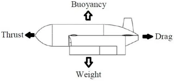
Figure 2.10: Acting forces for a moving AUV.
Generally, thrust could be defined as the changes of the momentum of the fluid that obeys 2nd and 3rd Newton law. This relation can be represented as Equation 2.3;
c i i e e f
t
v
m
v
m
T
(2.3)where Tf is the thrust, me is the ejected fluid mass, ve is the ejected fluid velocity, mi is
the initial fluid mass and vi is the initial fluid velocity. tc is the contraction time. This
equation could be simplified as in Equation 2.4, because in water jet mechanism, the fluid mass is not constant and varies according to time. Thus,
e e e
f v m v
dt dm
where ṁeis mass flow rate of the jetted fluid. Since mass flow rate is intricate to
measure, the mass flow rate could be substituted with ejected fluid volume,
V
f anddensity of the fluid, ρf. Now, Equation 2.4 becomes;
e f f
f
V
v
T
(2.5)Using continuity flow relation, Equation 2.5 could be simplified as (Li et al., 2015);
2 e n f f
A
v
T
(2.6)An is the nozzle opening area. An and ρf are constants in the thrust and velocity relation.
Based on this relation, it is obvious that the thrust will increase exponentially as the ejected fluid velocity are increased.
inertia. The load cell will be attached at the beam. Once the thruster operates, small displacement could be read by the load cell and the data will be converted into thrust force. Figure 2.12 depicted the example of gage thrust measurement technique done by Guo et al. (2010). The thrust force, Tf could be determined using Equation 2.10;
0
l fL
ZE
T
(2.10)where Z is the second moment area, E is the Young Modulus of the beam, Ll is the
length of the force point to the strain gage and ε0 is the lever deformation. ε0 value can
be obtained using the strain gage.
[image:42.595.113.524.415.580.2]
(a) (b)
Figure 2.11: Bollard Pull Test (Muljowidodo et al., 2009); (a) Schematic diagram and (b) Actual test
Thruster Reverse force Gage
Thrust
Figure 2.12: Thrust measurement using gage test (Guo et al., 2010)
Generally, drag can be measured using the drag formula (Shi et al., 2015; Zakrisson et al., 2015);
D f b AUV
D C u A
F 2
2 1
(2.11)
where FD is the drag force, CD is the drag coefficient, ρf is water density, ub and AAUV
are both AUV velocity and contacting area of the AUV during the motion. Drag coefficient could be measured during experiment or simulation (Karim et al., 2008; Joung et al., 2009). Based on Equation 2.11, it is obvious that drag depends on the fluid density, speed of the object and shape of the object.
2.3.3 Dimensionless parameter
REFERENCES
Alam, K., Ray, T. and Anavatti, S. G. (2014). Design and construction of an autonomous underwater vehicle, Neurocomputing, 142, pp.16–29.
Alotta, B., Pugi, L., Bartolini, F., Ridolfi, A., Costanzi, R., Monni, N. and Gelli, J. (2014). Preliminary design and fast prototyping of an autonomous underwater vehicle propulsion system, Journal of Engineering for the Maritime Environment, 229(3), pp.248-272.
Aras, M.S.M., Kasdirin, H. A., Jamaluddin, M. H. and Basar, M. F. (2009). Design and development of an autonomous underwater vehicle (AUV-FKEUTeM), Proceedings of Malaysian Technical Universities Conference on Engineering and Technology (MUCEET), 20-22 June, Kuantan, Universiti Malaysia Pahang, pp.57-61.
Barbar, A., Najem, J., Donald, L. and Blotman, J. (2011). Design and development of bio-inspired underwater jellyfish like robot using Ionic Polymer Metal Composite (IPMC) actuators, Proceedings of Society of Photo-Optical Instrumentation Engineers (SPIE), 7976, pp.1-11.
Bar-Cohen, Y. (2004). EAP as artificial muscles - progress and challenges, Smart Structures and Materials, Electroactive Polymer and Devices (EAPAD), Proceedings of Society of Photo-Optical Instrumentation Engineers (SPIE), 5385, pp.10-16.
Bartol, I. K., Krueger, P. S., Stewart, W. J. and Thompson, J. T. (2009). Hydrodynamics of pulsed jetting in juvenile and adult brief squid Lolliguncula brevis: evidence of multiple jet ‘modes’ and their implications for propulsive efficiency, The Journal of Experimental Biology, 212, pp.1889-1903.
Benetazzo, F., Ippoliti, G., Longhi, S. and Raspa, P. (2015). Advanced control for fault-tolerant dynamic positioning of an offshore supply vessel, Ocean Engineering, 106, pp.472-484.
Bennet, M. D., Leo, D. J., Wilkes, G. L., Beyer, F. L. and Pechar, T. W. (2006). A model of charge transport and electromechanical transduction in ionic liquid-swollen Nafion membranes, Polymer, 47, pp.6782-6796.
Blidberg, R. (2001) The Development of Autonomous Underwater Vehicles (AUV); A Brief Summary, IEEE International Conference on Robotics and Automation (ICRA), 21-26 May, Seoul, IEEE, pp.1-12.
Campos, M. M. and Codina, G. O. (2015). Optical sensors and methods for underwater 3D reconstruction, Sensors, 15, pp.31525-31557.
International Conference on Advanced Intelligent Mechatronics, 24-28 July, California, IEEE, pp.60-65.
Chen, Z., Tan, X., Will, A. and Zie, C. (2007). A dynamic model for Ionic Polymer– Metal Composite sensors, Smart Material and Structure, 16, pp.1477–1488. Chopra, I. (2002). Review of State of art of smart structures and integrated systems,
The American Institute of Aeronautics and Astronautics (AIAA) Journal, 40(11), pp.2145 – 2187.
Chu, W. S., Lee, K. T., Song, S. H., Han, M. W., Lee, J. Y., Kim, H. S., Kim, M. S., Park, Y. J., Cho, K. J., and Ahn, S. H. (2012). Review of biomimetic underwater robots using smart actuators, Int. Journal of Precision Engineering and Manufacturing, 12(7), pp.1281-1292.
Chung, C. K., Fung, P. K., Hong, Y. Z., Ju, M. S., Lin, C.C.K. and Wu, T.C. (2006). A novel fabrication of Ionic Polymer-Metal Composites (IPMC) actuator with silver nano-powders, Sensors and Actuators B, 117, pp.367–375.
Cole, M., Lindeque, P., Halsband, C. and Galloway, T. S. (2011). Microplastics as contaminants in the marine environment: A review, Marine Pollution Bulletin, 62, pp.2588-2597.
Colgate, J. E. and Lynch, K. M. (2004). Mechanics and control of swimming: A review, IEEE Journal of Oceanic Engineering, 29(23), pp.660 – 673.
Cordova, F. G. and Gonzalez, A. G. (2013). Intelligent navigation for a solar powered unmanned underwater vehicle, International Journal of Advanced Robotic System, 10(185), pp.1-11.
Curtin, T., Crimmins, D., Curcio, J., Benjamin, M., Roper, C. (2005). Autonomous underwater vehicles: trends and transformations, Marine Technology Society Journal, 39, pp.75–86.
Desforges, J. P. W., Galbraith, M., Dangerfield, N. and Ross, P. S. (2014). Widespread distribution of microplastics in subsurface seawater in the NE Pacific Ocean, Marine Pollution Bulletin, 79, pp.94-99.
Gharib, M., Rambod, E. and Shariff, K. (1998). A universal time scale for vortex ring formation, Journal of Fluid Mechanics, 360, pp.121–140.
Gilly, W. F., Zeidberg, L. D., Booth, J. A. T., Stewart, J. S., Marshall, G., Abernathy, K. and Bell, L. E. (2012). Locomotion and behaviour of Humbolt squid, Dosidicus gigas, in relation to natural hypoxia in the Gulf of California, Mexico, The Journal of Experimental Biology, 215, pp.3175-3190.
Gosline, J. M. and De Mont, M. E. (1985). Jet propelled in swimming squids, Science America, 256, pp.96–103.
Gosline, J. M., Steeves, J. D., Harman, A. D., De Mont, M. E. (1983). Patterns of circular and radial mantle muscle activity in respiration and jetting of the squid loligo opalescens, Journal of Experimental Biology, 104, pp.97–109.
Guo, J., Guo, S. and Li, L. (2016). Design and characteristic evaluation of a novel amphibious spherical robot, Microsystem Technologies, pp.1-14.
Guo, S., Lin, X. and Hata, S. (2009). A conceptual design of vectored water-jet propulsion system, Proceedings of the 2009 IEEE International Conference on Mechatronics and Automation, 9-12 August, Changchun, IEEE, pp.1190-1195. Guo, S., Lin, X., Tanaka, K and Hata, S. (2010). Modelling of water jet propeller for
underwater vehicles, Proceedings of the 2010 IEEE International Conference on Automation and Logistics, 16-20 August, Hong Kong and Macau, IEEE, pp.92-97.
Ha, N. S., Goo, N. S. and Yoon, H. K. (2011). Development of a propulsion system for a biomimetic thruster, Chinese Science Bulletin, 56(4), pp.432-438.
He, Q., Yu, M., Zhang, X. and Dai, Z. (2013). Electromechanical performance of an ionic polymer-metal composite actuator with hierarchical surface texture, Smart Materials and Structures, 22(5), pp.1-11.
Higham, T. E. (2007). Feeding, fins and braking manoeuvres: locomotion during prey capture in centrarchid fishes, The Journal of Experimental Biology, 210, pp.107-117.
Huber, J. E., Fleck, N.A. and Ashby, M. F. (1997). The selection of mechanical actuators based on performance indices, Proceedings of Royal Society London A, 453, pp.2185-2205.
Hunter, I. W. and Lafontaine, S. (1992). A comparison of muscle with artificial actuators, Solid-State Sensor and Actuator Workshop, IEEE 5th Technical Digest, 22-25 June, South Carolina, IEEE, pp.178-185.
Husaini, M., Samad, Z and Arshad, M. R. (2009). CFD simulation of cooperative AUV motion, Indian Journal of Marine Sciences, 38(3), pp.346-351.
Jang, H., Verma, A. and Mahesh, K. (2012). Predicting unsteady loads in marine propulsor crashback using large eddy simulation, International Journal od Rotating Machinery, 2012, pp.1-9.
Ji, A., Park, H. C., Nguyen, Q. V., Lee, J. W. and Yoo, Y. T. (2009). Verification of beam models for ionic polymer-metal composite actuator, Journal of Bionic Engineering, 6, pp.232–238.
Joung, T. H., Sammut, K., He, F. and Lee, S. K. (2012). Shape optimization of an autonomous underwater vehicle with a ducted propeller using computational fluid dynamics analysis, International Journal of Naval Architecture and Ocean Engineering, 4(1), pp.44-56.
Joung, T., Sammut, K., He, F., and Lee, S. K., (2009). A study on the design optimization of an AUV by using computational fluid dynamic analysis, The Nineteenth International Offshore and Polar Engineering Conference, 21-26 June, Osaka, The International Society of Offshore and Polar Engineers (ISOPE), pp.21-26.
Kanno, R., Tadokoro, S., Taamori, T. and Hattori, M. (1995). Linear approximate dynamic model of ICPF (Ionic Conducting Polymer Gel Film) actuator, Proceedings of the 1996 IEEE International Conference on Robotics and Automation, 22-28 April, Minneapolis, IEEE, pp.219-225.
Karim, M. M., Rahman, M. M. and Alim, M. A. (2008). Numerical computation of viscous drag for asymmetric underwater vehicles, Jurnal Mekanikal, 26, pp.9-21.
Kim, B., Kim, B. M., Ryu, J. and Oh, I. H. (2003). Analysis of mechanical characteristics of the ionic polymer metal composite (IPMC) actuator using cast ion-exchange film, Smart Structures and Materials: Electroactive Polymer and Devices (EAPAD), Proceedings of Society of Photo-Optical Instrumentation Engineers (SPIE), 5051(486), pp.1-11.
Kim, K. J. and Shahinpoor, M. (2002). A novel method of manufacturing three-dimensional ionic polymer metal-composites (IPMCs) biomimetic sensors, actuators and artificial muscles, Polymer, 43, pp.797–802.
Kim, O., Shin, T. J. and Park, M. J. (2013). Fast low-voltage electroactive actuators using nanostructured polymer electrolytes, Nature Communications, 4(2208), pp.1-9.
Krieg, M. and Mohseni, K. (2008). Thrust characterization of a bioinspired vortex ring thruster for locomotion of underwater robots, IEEE Journal of Oceanic Engineering, 33(2), pp.123-132.
Krieg, M. and Mohseni, K. (2010). Dynamic modelling and control of biologically inspired vortex ring thrusters for underwater robot locomotion, IEEE Transactions on Robotics, 26(3), pp.542-554.
Krishnan, G. and Mohseni, K. (2010). An experimental study of a radial wall jet formed by the normal impingement of a round synthetic jet, European Journal of Mechanics B/Fluids, 29(4), pp.269-277.
Krueger, P. S., Moslemi, A. A., Nichols, J. T., Bartol, I. K., and Stewart, W. J. (2008). Vortex rings in bio-inspired and biological jet propulsion, Advances in Science and Technology, 58, pp.237–246.
Lee, M. J., Jung, S. H., Lee, S., Mun, M.S. and Moon, I. (2006a). Control of IPMC-based artificial muscle for myoelectric hand prosthesis, The First IEEE/RAS-EMBS International Conference on Biomedical Robotics and Biomechatronics, 20-22 February, Pisa, IEEE, pp.1172-1177.
Lee, S. G., Park, H.C., Pandita, S. D. and Yoo, Y. (2006b). Performance improvement of IPMC (Ionic Polymer Metal Composites) for a flapping actuator, International Journal of Control, Automation and Systems, 4(6), pp.748-755.
Lee, S. J., Han, M. J., Kim, S. J., Jho, J. Y., Lee H. Y. and Kim, Y. H. (2006c). A new fabrication method for IPMC actuators and application to artificial fingers, Smart Materials and Structures, 15(5), pp.1217–1224.
Lee, S., Kim, K. J. and Park, H. C. (2006d). Modeling of an IPMC actuator-driven zero-net-mass-flux pump for flow control, Journal of Intelligent Material Systems and Structures, 17(6), pp.533-541.
Legras, M., Hirata, Y., Nguyen, Q. T., Langevin, T. and Matayer, M. (2002). Sorption and diffusion behaviors of water in Nation 117 membranes with different counter ions, Desalination, 147, pp.351-357.
Lepora, N. F., Vershure, P. and Prescott, T. J. (2013). The state of the art in biomimetics, Bioinspiration and Biomimetics, 8(1), pp.1-11.
Li, M., Guo, S., Hirata, H. and Ishihara, H. (2015). Design and performance of an amphibious spherical robot, Robotics and Autonomous Systems, 64, pp.21-34. Lin, X. and Guo, S. (2012). Development of a spherical underwater robot equipped
with multiple vectored water-jet-based thrusters, Journal of Intelligent & Robotic Systems, 67(3), pp.307-321.
Lin, X., Guo, S., Tanaka, K. and Hata, S. (2011). Underwater experiments of a water-jet-based spherical underwater robot, IEEE International Conference on Mechatronics and Automation (ICMA), 7-10 August, Beijing, IEEE, pp.738- 742.
muscle technology: Physical principles and naval prospects, IEEE Journal of Oceanic Engineering, 29(3), pp.706–727.
Marut, K., Stewart, C., Michael, T., Villanueva, A and Priya, S. (2013). A jellyfish-inspired jet propulsion robot actuated by an iris mechanism, Smart Materials and Structures, 22, pp.1-12.
Marut, K. J. (2014). Underwater Robotic Propulsors Inspired by Jetting Jellyfish, Master Thesis, Virginia Polytechnic Institute and State University.
Maxey, M. R. (2011). Biomimetics and cilia propulsion, Journal of Fluid Mechanics, 678, pp.1-4.
Mirfakhrai, T., John D. W. Madden, and Ray H. Baughman, (2007). Polymer artificial muscles, Materials Today, 10(4), pp.30–38.
Moslemi, A. A. and Krueger, P. S. (2010). Propulsive efficiency of a biomorphic pulsed-jet underwater vehicle, Bioinspiration and Biomimetics, 5, pp.1-14. Muljowidodo, K., Sapto Adi, N., Prayogo, N. and Budiyono, A. (2009). Design and
testing of underwater thruster for SHRIMP-ROV ITB, Indian Journal of Marine Sciences, 38(3), pp.338-345.
Najem, J., Sarles, S. A., Barbar, A. and Leo, D. J. (2012). Biomimetic jellyfish-inspired underwater vehicle actuated by ionic polymer metal composite actuators, Smart Materials and Structures, 21(9), pp.1-11.
Nemat-Nasser, S. and Wu, Y. (2006). Tailoring the Actuation of Ionic Polymer-Metal Composite, Smart Materials and Structures, 15, pp.909-923.
Nesteruk, I., Passoni, G. and Redaelli, A. (2014). Shape of aquatic animals and their swimming efficiency, Journal of Marine Biology, 2014, pp.1-9.
Neveln, I. D., Bai, Y., Snyder, J. B., Solberg, J. R., Curet, O. M., Lynch, K. M. and McIver, M. A. (2013). Biomimetic and bio-inspired robotics in electric fish research, The Journal of Experimental Biology, 216, pp.2501-2514.
Ng, F. C., Abas, A., Ishak, M. H. H., Abdullah, M. Z. and Abdul Aziz, M. S. (2016). Effect of thermocapillary action in the underfill encapsulation of multi-stack ball grid array, Microelectronics Reliability, 66, pp.143-160.
Nguyen, T. T., Goo, N. S., Nguyen, V. K., Yoo, Y. and Park, S. (2008). Design, fabrication and experimental characterization of a flap valve IPMC micropump with flexibly supported diaphragm, Sensors and Actuators A, 141(2), pp.640– 648.
O’Dor, R. K. (1988). The forces acting on swimming squid, Journal Experimental Biology, 137, pp.421-442.
O’Dor, R. K. (2002). Telemetered cephalopod energetics: swimming, soaring, and blimping, Integrative and Comparative Biology, 42(5), pp.106501070.
Olcay, A. B. and Krueger, P. S. (2010). Momentum evolution of ejected and entrained fluid during laminar vortex ring formation, Theoretical Computational Fluid Dynamics, 24(5), pp.465-482.
Otis, J. D., (2013). Electromechanical characterization and locomotion control of IPMC biomicrorobot, Advances in Materials Science and Engineering, 2013, pp.1-17.
Pak, J. J., Cha, S. E., Ahn, H. J. and Lee, S. K. (2001). Fabrication of Ionic Polymer Metal Composites by Electroless Plating of Pt, Proceedings of the 32nd International Symposium on Robotics (ISR), 19-21 April, Seoul, ISR, pp.1-5. Park, I. S., Kim, S. M. and Kim, K. J. (2007). Mechanical and thermal behaviour of
Ionic Polymer-Metal Composites: effects of electroded metals, Smart Materials and Structures, 16(4), pp.1090-1097.
Peng, H., Ding, Q. and Li, H. (2009). Fabrication of ionic polymer-metal composites (IPMCs) and robot design, Frontiers of Mechanical Engineering China, 4(3), pp.332–338.
Plasticintl (2016). Low Density Polyethylene (LDPE) Datasheet [Online]. [Access on 29 October 2016]. Available from the World Wide Web: http://www.plasticsintl.com/datasheets/LDPE.pdf.
Praveen, P. C. and Krishnankutty, P.(2013). Study on the effect of body length on the hydrodynamic performance of an axi-symmetric underwater vehicle, Indian Journal of Geo-Marine Sciences, 42(8), pp.1013-1022.
Punning, A., Kruusmaa, M. and Aabloo, A. (2007). Surface resistance experiments with IPMC sensors and actuators, Sensors and Actuators A, 133, pp.200–209. Radhakrishnan, S. and Kar, S. B. (2006). Response characteristics of conducting
polypyrrole bi-layer actuators: Role of backing layer polymer, Sensors and Actuators B, 119(1), pp.94-98.
Reimenschneider, J. (2009). Characterization and modeling of CNT based actuators, Smart Structures and Materials, 18(10), pp.1-9.
Schultz, J. A. (2009). Autonomous Underwater Vehicle (AUV) propulsion system analysis and optimization, Master Thesis, Virginia Polytechnic Institute and State University.
Serchi, F. G., Aienti, A. and Laschi, C. (2013). Biomimetic vortex propulsion: toward the new paradigm of soft unmanned underwater vehicles, IEEE/ASME Transactions on Mechatronics, 18(2), pp.484-493.
Shahinpoor, M. and Kim, K. J. (2001). Ionic Polymer Metal Composite: I. Fundamentals, Smart Materials and Structures, 10, pp.819-833.
Shahinpoor, M. and Kim, K. J. (2002). Novel ionic metal-polymer composites equipped with physically loaded particulate electrode as biomimetic sensors, actuators and artificial muscles, Sensors and Actuators A, 96, pp.125-132. Shariff, K. and Leonard, A. (1992). Vortex rings, Annual Review of Fluid Mechanics,
24(1), pp.235-279.
Sharma, P. and Yendluri, D. R. (2013). Review on biomimetic robofish, International Journal of Advancements in Research and Technology, 2(6), pp.99-111.
Shi, L., Guo, S. and Asaka, K. (2010). A novel jellyfish-like biomimetic microrobot, The 2010 IEEE/ICME International Conference on Complex Medical Engineering, 7-10 August, Beijing, IEEE, pp.227-281.
Shi, L., Guo, S., Mao, S., Li, M. and Asaka, K. (2013). Development of a lobster-inspired underwater microrobot, International Journal of Advanced Robotic Systems, 10, pp.1-15.
Shi, W., Wang, D., Atlar, M., Guo, B. and Seo, K. C. (2015). Optimal design of a thin-wall diffuser for performance improvement of a tidal energy system for an AUV, Ocean Engineering, 108, pp.1–9.
Smith, B. L. and Glezer, A. (1998). The formation and evolution of synthetic jets, Physics of Fluids, 1(9), pp.2281-2297.
Staaf, D. J., Gilly, W. F. and Denny, M. W. (2014). Aperture effects in squid jet propulsion, The Journal of Experimental Biology, 217, pp.1588-1600.
Stemme, E. and Stemme, G. 1993. A valveless diffuser/nozzle-based fluid pump. Sensors and Actuators A, 39, pp.159-167.
Stevenson, P., Furlong, M. and Dormer, D. (2009). AUV design – shape, drag and practical issues, Sea Technology, 50(1), pp.41-44.
Tan, A. C. H. and Hover, F. S. (2010). Thrust and wake characterization in small, robust ultrasonic thrusters, OCEANS, pp.1-9.
Tan, X. D. Kim, N. Usher, D. Laboy, J. Jackson, A. Kapetanovic, J. Rapai, B. Sabadus and X. Zhou, (2006). An autonomous robotic fish for mobile sensing, Proceedings of the IEEE/RSJ International Conference on the Intelligent Robotics and Systems, 9-15 October, Beijing, IEEE, pp. 5425-5429.
Thomas, A. M. P., Milano, M., G’Sell, M. G., Fischer K. and Brudich, J. (2005). Synthetic Jet Propulsion for Small Underwater Vehicles, IEEE International Conference on Robotics and Automation, Barcelona, IEEE, pp. 181-187. Tremblay, I., Do, M. S. and Guderley, H. (2015). When behaviour and mechanics
meet: scallop swimming capacities and their hinge ligament, Journal of Shellfish Research, 34(2), pp.203-212.
Vahabi, M, Mehdizadeh, E., Kabganian, M. and Barazandeh, F. (2011). Experimental identification of IPMC actuator parameters through incorporation of linear and nonlinear least squares methods, Sensors and Actuators A, 168(1), pp.140-148. Vasilescu, I., Varshavkaya, P., Kotay, K. and Rus, Daniela. (2005). Autonomous
modular optical underwater robot (AMOUR) design, Prototype and Feasibility Study, Proceedings of the 2005 IEEE International Conference on Robotics and Automation (ICRA), 18-22 April, IEEE, pp.1603-1609.
Villanueva, A., Marut, K. J., Micheal, T. and Priya, S. (2013). Biomimetic autonomous robot inspired by the Cyanea capillata (Cyro), Bioinspiration and Biomimetics, 8(4), pp.1-18.
Villanueva, A., Smith, C. and Priya, S. (2011). A biomimetic robotic jellyfish (Robojelly) actuated by shape memory alloy composite actuators, Bioinspiration and Biomimetics, 6(3), pp.1-16.
Vysohlid, M. and Mahesh, K. (2012). Large eddy simulation of crashback in marine propellers, 44th American Institute of Aeronautics and Astronautics (AIAA) Aerospace Sciences Meeting and Exhibit, pp.1-12.
Wang, Y., Wang, Z. and Li, J. (2011). Initial design of a biomimetic cuttlefish robot actuated by SMA Wires, IEEE 3rd International Conference on Measuring Technology and Mechatronics Automation, 6-7 January, Shanghai, IEEE, pp.425 – 428.
Wen, L., Wang, T. M., Wu, G. H. and Liang, J. H. (2012). Hydrodynamic investigation of a self-propelled robotic fish based on a force-feedback control method, Bioinspiration and Biomimetics, 7(3), pp.1-17.
Won, D. J., Kim, J. and Kim, J. (2015). Design optimization of duct-type AUVs using CFD analysis, Intelligent Service Robotics, 8(4), pp.233-245.
Xu, S., Liu, B. and Hao, L. (2008) A small remote operated robotic fish actuated by IPMC, Proceedings of the 2008 IEEE International Conference on Robotics and Biomimetics, 22-25 February, Bangkok, IEEE, pp.1152-1156.
Xu, Y. and Mohseni, K. (2012). Robust adaptive control of underwater vehicles with biologically inspired vortex ring thrusters, International Federation of Automatic Control (IFAC) Proceedings Volumes, 45(5), pp.387-392.
Xu, Y., Zong, G., Bi, S. and Gao, J. (2007). Initial development of a flapping propelled unmanned underwater vehicle (UUV), IEEE International Conference on Robotics and Biomimetics (ROBIO), 15-18 December, Sanya, IEEE, pp.524-529.
Ye, X. F., Hu, Y. N., Guo, S. and Su, D. Y. (2008). Driving Mechanism of a new jellyfish-like microrobot, Proceedings of 2008 IEEE International Conference on Mechatronics and Automation, 5-8 August, Takamatsu, IEEE, pp.563-568. Yeom, S.W. and Oh, I. K. (2009). A biomimetic jellyfish robot based on ionic polymer
metal composite actuators, Smart Material Structure, 18(8), pp.1-10.
Yip, J., Feng, L. S., Hang, C. W., Marcus, C. W. and Wai, K. C. (2011). Experimentally validated improvement of IPMC performance through alternation of pretreatment and electroless plating processes, Smart Material Structures, 20(1), pp.1–8.
Yu, H. and Kim, E. S. (2004). Ultrasonic underwater thruster, 17th IEEE International Conference on Micro Electro Mechanical Systems (MEMS): Maastricht MEMS 2004, Technical Digest, pp.486-489.
Yu, J. Z., Chen, E. K., Wang, S. and Tan, M. (2005). Motion Controls algorithms for a free-swimming biomimetic robot fish, Acta Automatica Sinica, 31(4), pp.537-542.
Yu, M., Shen, H. and Zhen-dong, D. (2007). Manufacture and performance of Ionic Polymer-Metal Composites, Journal of Bionic Engineering, 4, pp.143−149. Yue, C., Guo, S., Li, M., Li, Y., Hirata, H. and Ishihara, H. (2015). Mechatronic system
and experiments of a spherical underwater robot: SUR-II, Journal of Intelligent & Robotic Systems, 80(2), pp.325-340.
Yuh, J. (2000a). Underwater robotics, IEEE International Conference on Robotics and Automation (ICRA), San Francisco, IEEE, pp.932–937.
Yuh, J., (2000b). Design and control of autonomous underwater robots: A survey, Autonomous Robots, 8(1), pp.7–24.
Zhang, L., Demin, X., Mingyong, L. and Weisheng, Y. (2009). Cooperative navigation and localization for multiple UUVs, Journal of Marine Science and Application, 8(3), pp.216-221.