COMMISSION OF THE EUROPEAN COMMUNITIES
CAMAC
ORGANISATION OF MULTI-CRATE SYSTEMS
Specification of the Branch Highway and CAMAC Crate Controller Type A
1972
Joint Nuclear Research Centre
Jspra Establishment - Italy
LEGAL NOTICE
This document was prepared under the sponsorship of the Commission
of the European Communities.
Neither the Commission of the European Communities, its contractors
nor any person acting on their behalf :
make any warranty or representation, express or implied, with respect
to the accuracy, completeness, or usefulness of the information contained
in this document, or that the use of any information, apparatus, method
or process disclosed in this document may not infringe privately owned
rights; or
assume any liability with respect to the use of, or for damages resulting
from the use of any information, apparatus, method or process disclosed
in this document.
This report is on sale at the addresses listed on cover page 4
at the price of B.Fr.
60.-When ordering, please quote the EUR number and the title
which are indicated on the cover of each report.
Printed by Guyot s.a., Brussels
Luxembourg, April 1972
COMMISSION OF THE EUROPEAN COMMUNITIES
EU.
CAM Sped
Comm Joint 1 ESONl Luxeml
TheC under thl tion, wit, extension tion betw, computer. detail to e; and produc there are gei Highway.
EUR 4600 ,
CAMAC - ORG Specification of t
Commission of the Joint Nuclear Res, ESONE Committe Luxembourg, April
The CAMAC Spee under the auspices oi tion, within a CAM, extension to the specil tion between the crat computer. The connect detail to ensure comp, and production. A stan there are general recomr Highway.
',TEMS
Jller Type A
-~~.1·e
-&dtmt - ItalyABSTRACT
The CAMAC Specification (EUR 4100 e), drawn up by European laboratories under the auspices of the ESONE Committee, defined the means of communica-tion, within a CAMAC crate, between modules and a crate controller. This extension to the specification defines a CAMAC Branch Highway for communica-tion between the crate controllers in seven crates and a system controller or computer. The connections from units to the Highway are specified in sufficient detail to ensure compatibility between units from different sources of design and production. A standard CAMAC Crate Controller Type A is specified, and there are general recommendations for all crate controllers used with the Branch Highway.
This specification does not invalidate other methods of interconnection, including those using crate controllers dedicated to specific computers. The USAEC NIM Committee has endorsed this specification and will publish an identical document (TID-25876).
KEYWORDS
DATA TRANSMISSION
TECHNICAL SPECIFICATIONS
COMPUTERS
1.
Introduction
7
2.
Interpretation of this Document
7
3.
The Branch
8
4.
Use of Lines at a Branch Highway Port
9
4.1 Command
9
4.1.1 Crate Address (BCRl - BCR7)
9
4.1.2 Station Number (BN 1, 2, 4, 8, 16)
9
4.1.3 Sub-Address (BAl, 2, 4, 8)
4.1.4 Function (BFl, 2, 4, 8, 16)
11
4.2 Data and Status
11
4.2.1 Read and Write (BRWl - BRW24)
11
4.2.2 Response (BO)
11
4.2.3 Command Accepted (BX)
12
4.3 Timing (BTA, BTBl - BTB7)
12
4.4 Demand Handling
12
4.4.1 Branch Demand (BD)
12
4.4.2 Graded-L Request (BG)
13
4.5 Common Controls
13
4.5.1 Branch Initialise (BZ)
13
4.5.2 Dataway Initialise (Z), Clear (C) and Inhibit (I)
13
4.6 Reserved Lines (BVl - BV7)
13
5.
Branch Operations
14
5.1 Command Mode Operations
15
5.1.1 Read Operations: Phase 1
15
5.1.2 Read Operations: Phase 2
15
5.1.3 Read Operations: Phase 3
15
5.1.4 Read Operations: Phase 4
17
5.1.5 Write Operations
17
5.1.6 Other Command Operations
17
5.2 Graded-L Operations
17
5.3 Differential Delays (Skew)
i9
4
-6.
Connectors
6.1 Connection to Screen of Branch Highway Cable
7
Signal Standards at Branch Highway Ports
7.1
7.2
7.3
7.4
Appendix 1
A1.1 A1.2 A1.3 A1.4 A1.5 A1.6 A1.7 A1.8 A1.9 A1.10
Appendix 2
Index
Inputs
Outputs
Terminations
Off-I ine and Power-off Conditions
Specification of CAMAC Crate Controller Type A
CAMAC Crate Controller Type A Other Crate Controllers
General Features Front Panel Dataway Signals
A1.5.1 A1.5.2 A1.5.3 A1.5.4
Data Signals Command Signals Common Control Signals Patch Connections
Demand Handling
A1.6.1 A1.6.2 A1.6.3
Branch Demand Graded-L
Pull-up for GL and L Lines
Timing Requirements
A1.7.1 A1.7.2 A1.7.3
Command Mode Operations with Dataway S1. S2 and B Graded-L Operations
Command Mode Operations without Dataway S1. S2 or B
Commands Implemented by Crate Controller Type A LAM-Grader Connector
A1.9.1 A1.9.2 A1.9.3 A1.9.4
Signal Standards Timing: Branch Demand Timing: Graded-L Operations Timing: Command Mode Operations
Off-I ine State
The ESONE Committee
Table I
Table II
Table Ill
Table IV
Table V
Table VI
Table VII
Table VIII
Table IX
Table X
Figure 1
Figure 2
Figure 3
Figure 4
Figure 5
Figure 6
Figure 7
Signal Lines at Branch Highway Ports
Station Number Codes used in Crate Controllers
Sequence of Command Mode Operation
Sequence of Graded-L Operation
Standard Connector for Branch Highway Ports
Contact Assignments at Branch Highway Ports: By Signals
Contact Assignments at Branch Highway Ports·. By Contact Numbers
Signal Standards at Branch Highway Ports
Commands Implemented by CAMAC Crate Controller Type A
Contact Assignments for Rear Connector of Crate Controller Type A
CAMAC Branch: Chain Configuration
CAMAC Branch: Example of an Alternative Configuration
Timing of Branch Read Operation
Timing of Branch Write Operation
Branch Highway Ports: Arrangement of Connectors on Crate Controllers
Branch Highway Ports: Contact Layout (front view of fixed connector)
CAMAC Crate Controller Type A
10
11
16
18
20
21
22
24
30
31
37
37
38
38
39
40
6
1.
Introduction
The Dataway, defined in EURATOM Report EUR 4100e, is the basis of all CAMAC systems. It provides the means of inter-connection between modules and a crate controller within one crate. Multi-crate CAMAC systems can be organised as one or more larger structural units, called branches, in which a branch highway provides the means of inter-connection between crate controllers in seven crates and a branch driver.
This specification defines the signals, timing, and logical organisation of the connections from crate controllers and branch drivers to the branch highway through a standard 132-way connector. The internal structures of crate controllers and branch drivers, and the physical construction of the branch highway, are only defined where they affect compatibility between parts of the system.
An appendix defines in more detail those features of the crate controller that affect hardware and software compatibility. This appendix can be used either as the formal specification of a standard crate controller (CAMAC Crate Controller Type A)* or as general recommendations intended to promote uniformity between crate controllers.
2.
Interpretation of this Document
This document is a reference text describing and specifying the CAMAC Branch Highway.
Authorised translations are available in French, German and Italian. It should be read in conjunction with, and is supplementary to, the ratest revision of CAMAC Specification EUR 4100e. No part of this document is intended to supersede or modify EUR 4100e.
Mandatory clauses of the specification are written in bold type, as here, and are usually accompanied by the word •must•.
The word 'should' indicates a recommended or preferred practice which is to be followed unless there are sound reasons to the contrary ..
The word 'may' indicates good practice but leaves freedom of choice to the designer.
The word 'reserved' indicates that a feature must not be used until it has been more fully defined
by the ESONE Committee.
In order to claim compatibility with the CAMAC Branch Highway specification any equipment or
system must comply with the mandatory statements in both EUR 4100e and this specification, excluding
Appendix 1. Compatibility with the specification of the CAMAC Crate Controller Type A requires, in
addition, conformity with the mandatory sections of Appendix 1.
No licence or other permission is needed in order to use this specification.
8
-3.
The Branch
A multi-crate CAMAC system consists of one or more branches. each having a branch highway which is the means of inter-connection between a branch driver and crate controllers. During each branch operation the branch driver can communicate with a maximum of seven crate controllers. Al I branch drivers and crate controllers have standard branch highway ports* by which they arerconnected to the highway. Each port consists of a 132-way connector (for 65 signals and their individual return lines, plus cable screen) with defined contact allocations ana signal conventions. Each crate controller has two
identical internally-linked ports in order to allow the branch to have the chain configuration shown in Figure 1. Other configurations are possible, such as that shown in Figure 2. where the branch driver is ·not at the end of the branch and some crates are connected by only one port.
In addition to their normal on-line state, crate controllers have an off-line state which allows them to remain physically connected to the branch while ignoring (and not impeding) all branch operations. If required, the branch driver can recognise which crate addresses are associated with on-line crate controllers.
The basic mode of operation of the branch is the command mode. The branch driver, which is typically associated with a system control I er or computer, issues a command during each branch operation. This command includes crate address information to select one or more crate controllers. Each addressed crate controller accepts the command from the branch highway and generates the corresponding Dataway command (station number, sub-address and function). During read operations data signals are generated by a module on the Dataway Read lines, transferred to the data lines of the branch highway by the crate controller, and accepted by the branch driver. During write operations the branch driver generates data signals on the branch highway and these are transferred to the Dataway Write lines by the crate controller, and accepted by a module. During other command operations there is no transfer of read or write data via the branch highway.
The branch has two demand handling features which al low the branch driver to respond to Look-at-Me signals from modules. For single-level demand handling, which merely indicates the presence of demands without identifying them, the crate controllers combine the Look-at-Me signals to form a common Branch Demand signal. For multi-level demand handling, which allows the branch driver to identify 24 different demands, there is the Graded-L mode of branch operation. The branch driver issues a Graded-L Request (typically as the result of receiving the Branch Demand signal) and each on-line crate controller responds by selecting or rearranging its Look-at-Me signals to form a 24-bit Graded-L word. The Graded-L words from all crates are combined on the branch highway and presented to the branch driver.
At a branch highway port the Data lines are used in the command mode for information transfers in either direction between crate controllers and the branch driver. These lines are also used to convey the pattern of demands in the Graded-L mode.
Transfers in either mode through a branch highway port are controlled by inter-locking timing signals, which automatically adjust the timing of each branch operation to suit the actual transmission delays and controller performance that are encountered.
Initialise is the only common control signal that is transmitted through the branch highway port to the Dataway.
4.
Use of Lines at a Branch Highway Port
Each line at a branch highway port must be used in accordance with the mandatory requirements detailed in the following sections. Table I (overleaf) shows the titles, the standard designations, and the sources of the signals. Lines at a port are distinguished from corresponding lines in the Dataway by the prefix B, e.g., the function code is carried by F lines in the Dataway and BF lines at a branch highway
port.
4.1
Command
The command signals are used to control operations in the command mode, at which time the signal on the BG line (see 4.4.2) must be in the 'O' state. They are.transmitted by the branch driver on the BCR,
BN, BA
and BF I ines at the branch highway port (see below).4.1.1
Crate Address (BCR1 - BCR7)
The seven crate controllers that can be addressed during any branch operation must each be associated with a different BCR line (although all branch highway ports have provision for all seven BCR lines).
Each crate controller must therefore include means, such as a switch or patch connec-tion, for selecting the appropriate BCR line (referred to as BCRi). The assignment of BCR
lines to crates is not necessarily related to the physical arrangement of crates within the branch. The branch driver is permitted to generate signals simultaneously on more than one BCR line in order to select several crates for the same operation.
It is recommended that the crate controller should include a means of protection against spurious signals on the selected BCR line. For example, the incoming BCR signal or an internal signal derived from it may be conditioned by integration.
It will be seen later, in Section 4.3, that each crate controller is associated with not only one of the BCR I ines but also the corresponding one of seven BTB I ines.
The branch is not in a valid operating condition if more than one on-line crate
controller is connected to the same BCR line. A means of reducing the risk of this occurring is suggested in Section 5.4.
4.1.2
Station Number (BN1,
2,
4,
8,
16)
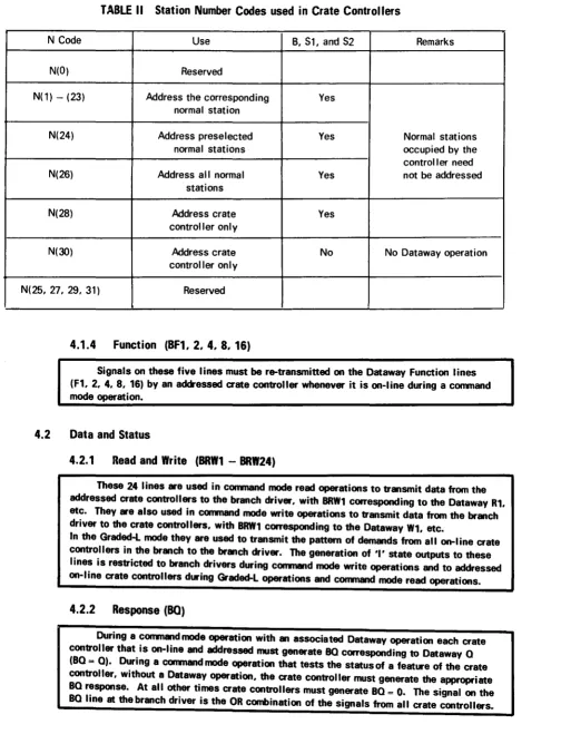
Signals on these five lines indicate the binary coded station number to be used within the selected crate or crates, and are decoded in the crate controller. In a crate controller the 32 codes are allocated as shown in Table II.
At least one normal station is occupied by the crate controller, and there are station number codes to address the remaining 23 normal stations individually. In addition there are codes to multi-address all normal stations or those stations indicated by the contents of a Station Number Register (SNR). Two further station number codes address the controller and its extensions irrespective of their location in the crate.
4.1.3
Sub-Address (BA 1,
2, 4, 8)
TABLE
I
Signal Lines at Branch Highway Ports
Title Designation Generated by Signal Use
Lines
Command Crate Address BCR1 - BCR7 Branch Driver
7
Each line addresses one crate in the branchStation Number BN1, 2. 4, 8, 16.
.
.
5
Binary coded station numberSub-address BA1, 2, 4, 8. H
.
4 As on Dataway A I ines
Function BF1, 2, 4, 8, 16.
.
.
5
As on Dataway F linesData Read/Write BRW1 - BRW24 Branch Driver (W) or
Crate Controller 24 For Read data, Write data, and
(R,GL) Graded-L
Status Response BO Crate Controller 1 As on Dataway Q line
Command
Accepted
BX
Crate Controller 1 As on Dataway X I ineTiming Timing A BTA Branch Driver 1 Indicates presence of Command,
etc.
Timing B BTB1 - BTB7 Crate Controller 7 Each line indicates presence of data, etc., from one crate controller
Demand Handling Branch Demand
BD
Crate Controller 1 Indicates presence of demandGraded-L Request BG Branch Driver 1 Requests 'Graded-L' Operation
Common Control Initialise
BZ
Branch Driver 1 As on Dataway Z Ii neReserved BV1 - BV7 7 For future requirements
An individual return line is provided for each signal line. Two lines are provided for a connection to the screen, if any, of the branch highway cable,
[image:12.877.113.780.225.606.2]TABLE II Station Number Codes used in Crate Controllers
N Code Use B, S1, and S2 Remarks
N(O) Reserved
N(l) - (23) Address the corresponding Yes
normal station
N(24) Address preselected Yes Normal stations
normal stations occupied by the
control I er need
N(26) Address all normal Yes not be addressed
stations
N(28) Address crate Yes
controller only
N(30) Address crate No No Dataway operation
control !er only
N(25, 27, 29, 31) Reserved
4.1.4
Function (BF1, 2, 4, 8, 16)
Signals on these five lines must be re-transmitted on the Dataway Function lines (F1, 2, 4. 8, 16) by an addressed aate controller whenever it is on-line during a command mode operation.
4.2
Data and Status
4.2.1
Read and Write (BRW1 -
BRW24)
These 24 lines are used in command mode read operations to transmit data from the addressed aate controllers to the branch driver, with BRW1 corresponding to the Dataway R1, etc. They are also used in conwnand mode write operations to transmit data from the branch driver to the crate controllers, with BRW1 corresponding to the Dataway W1, etc.
In the Graded-L mode they are used to transmit the pattern of demands from al I on-I ine crate controllers in the branch
to
the branch driver. The generation of 'I' state outputs to these lines is restricted to branch drivers during conmand mode write operations and to addressed on-line crate controllers during Graded-L operations and command mode read operations.4.2.2
Response (BO)
[image:13.691.37.542.97.757.2]12
-4.2.3
Command Accepted (BX)
During a command mode operation with an associated Dataway operation each crate controUer that is on-line and addressed must generate BX corresponding to Dataway X (BX = X). During all other command operations the crate controller must generate BX= 1
if it accepts the command and BX = 0 if it does not accept the command. The signal on the BX line at the branch driver is the OR combination of the signals from all crate controllers.
4.3
Timing (BTA, BTB1 - BTB7)
The timing of all command mode and Graded-L branch operations is controlled by branch timing signals. The branch driver initiates operations by signals on the common BTA line, and each addressed crate controller responds with a signal on its individual BTB line. All seven BTB lines are provided at each branch highway port, but each crate controller uses the line BTBi corresponding to the line BCRi by which it is addressed.
. Each on-line crate controller must generate BTBi = 1 when it is not addressed. The branch driver (and other crate controllers) can thus distinguish between BTB lines associated with on-line crates (BTBi = 1) and off-line or absent crates (BTBi = 0). (See Section 5.4).
The branch driver generates BTA = 1 to indicate that it is presenting a command or Graded-L request at its port, and maintains the signal until it has accepted the resulting BRW or BO informa-tion. Each crate controller generates BTBi = 0 when it has established data or BO information during branch operations.
The timing signals must be generated through intrinsic OR outputs and must have 10-90% signal transition times in the range 100 ± 50 ns.
It is recommended that the crate controller should include a means of protection against spurious signal.son the BTA line. For example, the incoming BTA signal or an internal signal derived from it may be conditioned by integration.
The full timing sequence is described in Section 5.
4.4
Demand Handling
Look-at-Me (L) signals from units in any part of the branch typically demand that an appropriate command or sequence of commands be generated. The branch therefore has two demand hand I ing features, one associated with the Branch Demand signal and the other with the Graded-L Request signal.
4.4.1
Branch Demand (BD)
Each crate controller can generate a demand signal, as any logical function of the L signals on the Dataway, through an intrinsic OR connection to the common Branch Demand line (BD). No restriction is placed on the time at which the BD signal may change, and therefore its 10-90% transition time must be in the range 100 ± 50 ns. The delay between the time when an L signal at the control station of the crate controller reaches a maintained
'1' or 'O' state and the time when the BD signal at the branch highway port of the same crate controller reaches a corresponding maintained '1' or 'O' state must not exceed 400 ns.
4.4.2
Graded-L Request (BG)
The branch driver initiates Graded-L mode operations by generating the Graded-L Request signal (BG). accompanied by BCR signals to all on-line crates. Each addressed
crate control I er generates a 24-bit Graded-L word on the BRW I ines. and the branch driver
reads the OR-combination of these words. The Dataway L signals in each crate are graded,
to select the relevant signals and assign them to the appropriate bits of the Graded-L word.
The grading process may, for example, be organised so that the branch driver reads a word indicating which crates require attention, or which actions (such as program
interrupts or autonomous transfers) are required. If the Graded-L requests from the branch are arranged in priority order in the word it is recommended, for uniformity, that a request on line BRW(n + 1) should have priority over a request on BRW(n).
Crate Controller Type A provides an additional means of access to the Look-at-Me information. (See Section A1.9.4 and Table IX).
4.5
Common Controls
4.5.1
Branch Initialise (BZ)
The Branch Initialise signal (BZ) is generated by the branch driver and has absolute priority over all other signals in the branch. The normal branch timing signals are not used with BZ. In order to allow crate controllers to discriminate against spurious signals of short duration the branch driver must maintain BZ = 1 for a minimum of 10 µs. It must not generate a Graded-Lor command mode operation during the following 5 µs period.
4.5.2
Dataway Initialise (Z), Clear (C) and Inhibit (I)
A crate controller receiving a Branch Initialise signal whose duration exceeds a minimum value (specified as 3± 1 µs) must initiate the generation of Dataway Initialise (Z) together with Busy (B) and Strobe S2 as required by EUR 4100e. The generation of S1. in addition to the mandatory B and S2, is optional and cannot be relied upon by other units connected to the Dataway.
All crate controllers must include some means of generating Dataway Clear (C) and
Inhibit (I) signals.
There are no branch highway lines for the Dataway common control signals Clear and Inhibit. A crate controller should generate Dataway Zand C signals, and generate and remove Dataway I, in response to command mode operations as defined in Table IX.
A crate controller may also generate Dataway common control signals in response to front panel signals, unless this is specifically prohibited (as in the case of Crate Controller Type A).
4.6
Reserved Lines (BV1 - BV7)
Signal and return lines, reserved for future requirements, are provided at all branch highway
ports. Where more than one port is provided, as in crate controllers. these reserved lines must be
I inked across between corresponding contacts.
14
-5.
Branch Operations
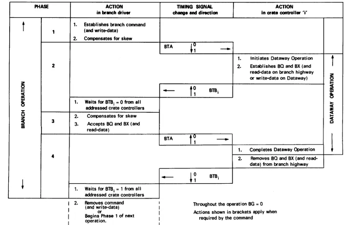
All transfers of information (read-data and write-data, Q, X and Graded-L) through branch highway ports are organised as branch operations. The timing of each operation is controlled by the branch timing signals BTA and BTB1 - BTB7, and can be divided into four phases as defined in Tables 111 and IV and Figures 3 and 4.
During Phase 1 the branch driver presents at its port one or more crate addresses either included in a command (together with write-data if required by the command), or accompanying a Graded-L Request. After a delay which compensates for signal skew it generates BTA = 1 to start the next phase.
During Phase 2 each addressed crate controller responds to BTA = 1 either by initiating the Dataway operation required by the command and presenting Q, X and any read-data at its port, or by presenting Graded-L information. It then generates BTBi
=
O on its individual BTB line. The branch driver starts the next phase when it has received BTBi=
O from al I addressed crate controllers.During Phase 3 the branch driver introduces a delay to compensate for signal skew and then accepts
Q, X and read-data, or the Graded-L information. It generates BTA =Oto start the next phase.
During Phase 4 each <1ddressed crate controller responds to BTA
=
O either by completing the Dataway operation and removing Q, X and read-data presented at its port, or by removing the Graded-L information. It then generates BTBi=
1 on its individual BTB line.The branch driver ends .Phase 4 when it has received BTBi
=
1 from al I addressed crate controllers, and is then free to begin another branch operation, either immediately (in which case new command, write-data, or Graded-L Request signals are set up) or later (in which case the existing signals are removed).The BTB lines corresponding to off-line or absent crate controllers remain in the 'O' state throughout the operation, and those corresponding to unaddressed on-line crates remain in the 'I' state.
The timing of the four phases is automatically adjusted by the sequence of timing signals to suit the actual signal delays occurring in the highway and the response times of crate controllers, etc.
The timing sequence for command mode operations is described in detail in Section 5.1. Graded-L operations are described in Section 5.2.
In practice the various branch, command and data signals are uni ikely to have precisely the same transmission delay, and this problem of signal skew is discussed in Section 5.3.
Branch operations will not be completed if the branch driver or addressed crate controllers fail to respond to the timing signals in the correct sequence. Branch drivers should therefore include some form of time-out feature to detect when an operation has not been completed within a reasonable time, so that appropriate action can be taken. Precautions against operations that would otherwise fail due to addressing absent or off-I ine crate controllers may be based on the means of recognising these crates described in Section 5.4.
The relationship between the branch highway operation and the Dataway operation in addressed crates must satisfy the requirements of Table Ill and EUR 4100e.
5.1
Command
Mode Operations
The sequence during a command mode operation is shown in Table Ill (see overleaf).
The following sections detail the four phases of a read operation and then outline the minor respects in which other operations differ. One or more crates may be addressed in any operation.
5.1.1
Read Operations:
Phase
1
The sequence during a read operation (Function codes O - 7) is illustrated in Figure 3.
Phase 1 involves actions in the branch driver, which presents the complete command [BCR, BN, BA, BF(O to 7)] at its port and then, after a delay to compensate for skew (see Section 5.3), generates BTA = 1 to initiate Phase 2.
5.1.2
Read Operations: Phase 2
After the transmission delay and signal transition time of the branch highway each crate controller receives the command signals and then, when they are stable, the timing signal BTA = 1. Phase 2 involves actions in all addressed crate controllers.
Each addressed crate controller (BCRi = 1) responds to BTA = 1 by beginning the timing sequence for a Dataway operation. In Figure 3 the Dataway operation is initiated by BTA after conditioning by integration, as recommended in Section 4.3. At time t0 of this operation (see Figure 9 of EUR 4100e) the Dataway Busy (B) and command signals must be generated. It is recommended that Band the N signals (derived by decoding the BN signals) should be generated when the crate controller has received BTA = 1, although the A and F signals (reproduced from the corresponding BA and BF signals) may be generated earlier (see Figures
3 and 4).
The addressed module responds to the command by transmitting Q, X and read-data which are established on the Dataway at time t3 (see Figure 9 of EUR 4100e). These signals are reproduced by the crate controller on the BRW, BO and BX lines at its branch highway port, and are maintained during Phase 3. (If the command addresses a register in the crate
controller, the read-data and Q information need not be transferred via the Dataway). When the controller has presented these BRW, BO and BX signals it generates BTB- .,,
o.
I
The branch driver initiates Phase 3 at some later time when it has received BTB = 0 from all addressed crates. Figure 3 shows BTBi = 0 from a particular crate, and also earlier and later BTB signals from other addressed crates. The branch driver waits for the last BTB signal. For example, it may detect the condition:
(BCR1 + BTB1 ).(BCR2 + BTB2) ... (BCR7 + BTB7) = 1
For each unaddressed crate BCRi = 1, and therefore the state of BTBi is ignored. For each addressed crate BCRi = 0, and therefore the condition is satisfied only when BTBi = 1.
5.1.3
Read Operations: Phase 3
PHASE
t
1
2
z
0
.:
cc
a: w
~
l::
u
;
34
i
TABLE Ill
Sequence of
Command Mode Operation
ACTION
in
brmach driver
1. Establishes branch command( and write-data)
2.
Compensates for skew1. Waits for BTBi = 0 from all addressed crate controllers
2.
Compensates for skew3.
Accepts BO and BX ( andread-data)
1. Waits for BTBi = 1 from all addressed crate controllers
2. Removes command (and write-data)
or
Begins Phase 1 of next operation.
TIMING SIGNAL
ACTION
change and direction
in crate controller 'i'BTA
-BTA
4
-,~
-1. Initiates Dataway Operation
2.
Establishes BO and BX (andread-data on branch highway or write-data on Dataway)
f~
BTBit~
-1. Completes Dataway Operation
2.
Removes BO and BX ( andread-data) from branch highway
i~
BTBiThroughout the operation BG
=
0Actions shown in brackets apply when required by the command
[image:18.881.100.783.228.669.2]5.1.4
Read Operations: Phase 4
Each addressed crate controller receives BTA
= 0 at some later time and is then free to
change its signal outputs to the BRW, BO and BX lines. During Phase 4 the crate controller takes any further action necessary to complete its Dataway operation.This may result in the read-data and Q signals changing (shown by broken lines in Figure 3), due to actions in addressed modules in response to Strobe S2.
At the end of the Dataway operation (t9) the crate controller removes the Dataway B and N s i gna Is. It a I so removes any "1 " state outputs to the BRW, BO and BX I i nes. It may do this immediately after the end of the Dataway operation at t9 (as shown in Figure 3) if it has gates between the Dataway and branch highway I ines. This is mandatory for Crate Controller Type A. Alternatively, it may remove the BRW and BO signals within 400 ns of the end of the Dataway operation at t
12 by relying on the addressed modules removing their outputs to the R and O I ines when they receive N = 0.
In either case the crate controller generates BTB;
= 1 when it has removed all "1" state
outputs to the branch BRW, BQ and BX lines, and the Dataway Band N lines.The branch driver ends Phase 4 at some later time when it has received BTB i = 1 from all addressed crates. For example it may detect the condition:
(BCRl + BTB1 ).(BCR2 + BTB2) ... (BCR7 + BTB7) = 1
For each unaddressed crate BCRi
= 1, and therefore the state of 8TB; is ignored. For each
addressed crate BCRi =o.
and therefore the condition is satisfied only when 8TB; = 1. The branch driver is then free to remove thecommand signals and to begin another command mode or Graded-L operation. The extreme case, shown in Figure 3, is when Phase 1 of the next operation follows immediately, so that the branch driver removes the command signals of one operation whilst setting up the command or Graded-L Request signals for the next.5.1.5
Write Operations
The sequence during a write operation (Function codes 16 - 23) is shown in Figure 4. The sequence is similar to that for a read operation (described above), except that write-data signals are generated by the branch driver for the same period as command signals. The signal BTBi
= 1 from the crate controller during Phase
4 has the additional significance that the write-data has been accepted.5.1.6
Other Command Operations
Operations with Function codes 8 - 15 and 24 - 31, which do not use the Read or Write lines of the Dataway, nevertheless use the Dataway O and Branch BO lines. Their timing is therefore similar to that of read operations as described above. The Dataway Q
signal is allowed to change during these operations (see EUR 4100e, Section 5.4.3), hence the BO signal may also change at any time.
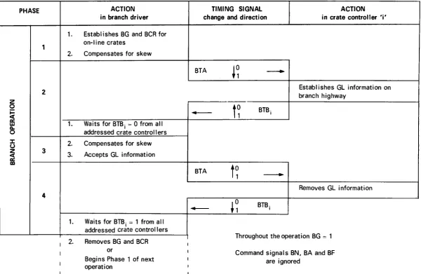
5.2
Graded-L Operations
PHASE
1
2
z
0j:: c(
a: UJ
ICI.
0
:c
u
z
c( 3
a: m
4
TABLE IV Sequence of Graded-L Operation
ACTION
in branch driver
1. Establishes BG and BCR for on-Ii ne crates
2.
Compensates for skew1. Waits for BTBi
= 0
from all addressed crate control I ers2.
Compensates for skew3.
Accepts GL information1. Waits for BTBi
=
1 from al I addressed crate controllers2.
Removes BG and BCR orBegins Phase 1 of next operation
TIMING SIGNAL ACTION
change and direction in crate controller 'i'
BTA
-BTA
--!~
- - +Establishes GL information on branch highway
t~
BTBit~
---+Removes GL information
!~
BTBiThroughout the operation BG
=
1Command signals BN, BA and BF are ignored
f--'
[image:20.888.146.747.255.646.2]During the Graded-L operation thebranch driver generates a set of BCR signals which must
have BCR.
=
0 on all lines corresponding to absent or off-line crate controllers and BCR. = 1 onI I
all lines corresponding to on-line crates. The BCR signals are accompanied by BG= 1.
It is recommended that the branch driver should derive the necessary informal ion about the state of the crate controllers from the BTB lines (see Section 5.4).
When the branch driver has presented the BCR signals and the Graded-L Request Signal it generates BTA = 1. In response to BG, BCRi, and BTA each on-line crate controller generates its Graded-L word through intrinsic OR outputs to the BRW lines at its branch highway port, without generating Dataway signals B, S1 or S2.
The grading process which forms the Graded-L word need not take place in the crate controller, but may involve another unit, such as the LAM-Grader associated with Crate
Controller Type A (see Section A1.9). The Dataway L signals are free to change at any time, and hence the BRW signals may also change.
Each addressed crate control I er generates BTBi = 0 when it has presented its Graded-L information to the BRW lines. The process of establishing the Graded-L information involves two special causes of delay. Firstly, if the L signal from a module has been gated off the Dataway by a preceding command mode operation there wi 11 be a de I ay of up to 400n s before L is re-established at the crate controller. Secondly, the Crate Controller Type A which is specified in Appendix 1 requires a separate LAM-Grader unit for processing L signals. This can involve additional delays in establishing L signals at the LAM-Grader unit, and in establishing the Graded-L signals at the crate controller.
When the branch driver has received BTBi
=
0 from all addressed crates it introduces a delay to al low for signal skew and then accepts the Graded-L word from the BRW I ines. Having done this it generates BTA= O.
When the crate controller receives BTA = 0 it removes the Graded-L information from the BRW lines and generates BTBi
=
1. Theoperation is completed when the branch driver receives BTBi=1from all addressed crate controllers and is free to remove the Graded-L Request and crate address signals.5.3 Differential Delays (Skew)
The delays encountered by the BTA and BTB signals are used to adjust the timing of the branch operation. However, there may be 'skew', or differential delays, between BTA and the individual bits of the command and write data signals received at the crate controller, and between BTB and the individual bits of the BRW, BO and BX signals received at the branch driver. The branch driver must introduce an appropriate delay before generating BTA
=
1, in order to ensure that all command signals are established at crate controllers before they receive BT A. Itmust also delay its internal action in response to BTB
=
0, in order to ensure that all data. BOand BX signals have become established.
This correction for skew may be either fixed, to cover a stated maximum skew, or adjustable to suit the specific application. Additional compensation for skew is permitted elsewhere in the branch.
5.4 Identification of On-line Crate Controllers
During the period between the end of Phase 4 of one branch operation and the beginning of Phase 2 of the next operation, the branch driver receives BTB.
=
1 from on-I ine crate controllers• I
20
-It is strongly recommended that the branch driver should identify the on-I ine crate controllers in this way immediately before each Graded-L operation in order to fulfil the mandatory requirement of Section 5.2 that all on-line crate controllers are addressed. Hence, the branch driver should generate BCRi - 1 if BTBi - 1.
The branch driver may also identify the on-I ine crate controllers before al I command mode operations, and compare them with the crate addresses specified in the command. This allows prompt detection of operations that would otherwise fail through addressing off-line or absent crate controllers, and avoids the much slower process of relying on a time-out feature which operates after the operation has failed (see Section 5).
A further application of this method of identifying on-line crate controllers would be to ensure that a crate controller cannot come on-line if there is already an on-line controller with the same address (see Section 4.1.1). Each crate controller could check that thecondition (BTBi + BCRi)
=
0 is satisfied before switching to the line state. It would remain off-line if there is already an on-line controller with the same address, either in the unaddressed state (BTBi = 1) or in the addressed state (BCRi=
1 ).6.
Connectors
The branch highway ports use the Hughes 132-way connectors defined in Table V, or equivalent types approved by the ESONE Convnittee. The fixed member used on the branch driver, crate controller and termination unit has 132 sockets. The free member used on cables has 132 pins.
The contact layout and outline dimensions of the fixed and free members are given (for information only) in Figures 5 and 6.
TABLE V
Standard Connector for Branch Highway Ports
Original Manufacturer: Hughes Aircraft Company
Connector Type: WSS Sub-miniature Rectangular Connector
Number of Contacts: 132
Polarising Code: BN
Catalogue Code Numbers:
Fixed member (socket moulding): WSS 0132 SOO BN OOO
Free member (pin moulding): WSS 0132 Pxx BN yyy
where Pxx yyy denotes type of jackscrew
Hood for free member: WAC 0132 H005 (for example)
The assignment of the signal and return lines is defined in Table VI, arranged by signals, and in Table VII, arranged by contact numbers.
[image:22.699.139.635.432.757.2]TABLE VI
Contact Assignments at Branch Highway Ports: By Signals
Signal Return Signal Signal Return
Signal
Contact Contact Contact Contact
-32 13 BCR1 93 76 BRW1
33
14 BCR2 94 77 BRW234
15 BCR3 95 78 BRW335 16 BCR4 Address Crate 96 79 BRW4
67 50 BCR5 97 80 BRW5
68 51 BCR6 98 81 BRW6
69 52 BCR7 99 82 BRW7
100 83 BRW8
36 17 BN1
103 84 BRW9
37 18 BN2
Station 104 85 BRW10
38 19 BN4 Address
105 86 BRW11
39
20 BN8106 87 BRW12
40
21 BN16 Read/Write107 88 BRW13 Lines
-41 1 BA1 108 89 BRW14
23 2 BA2 109 90 BRW15
24 3 BA4 Sub-Address 110 91 BRW16
25
4 BA8 112 113 BRW17114 115 BRW18
70 53 BF1
116 117 BRW19
71 54 BF2
118 119 BRW20
72 55 BF4 Function Code
124 125 BRW21
73 56 BF8
126 127 BRW22
74 57 BF16
128 129 BRW23
61 44 BO Response 130 131 BRW24
--
-63 46 BTA 26 5 BV1
31 10 BTB1 27 6 BV2
11 12 BTB2 28 7 BV3 Reserved
58 22 BTB3 29 8 BV4 Lines
132 92 BTB4 Timing 30 9 BV5
123 102 BTB5 64 47 BV6
120 101 BTB6 65 48 BV7
.
121 122 BTB7 66 49 BX Command
-
Accepted60 43 BO Demand 111 75 BSC Cable
59 42 BG Graded-L Request Screen
[image:23.693.57.509.120.730.2]TABLE VII
Contact Assignments at Branch Highway Ports: By Contact Numbers
Contact Contact Contact Contact Contact Contact Contact
Signal Signal Signal Signal Signal Signal Signal
1 BAl(R) 18 BN2(R) 35 BCR4 52 BCR7(R) 69 BCR7 86 BRWl l(R) 103 BRW9
2 BA2(R) 19 BN4(R) 36 BNl 53 BFl(R) 70 BFl 87 BRW12(R) 104 BRW10
3 BA4(R) 20 BN8(R) 37 BN2 54 BF2(R) 71 BF2 88 BRW13(R) 105 BRWl 1
4 BA8(R) 21 BN16(R) 38 BN4 55 BF4(R) 72 BF4 89 BRW14(R) 106 BRW12
5 BVl(R) 22 BTB3(R) 39 BN8 56 BF8(R) 73 BF8 90 BRW15(R) 107 BRW13
6 BV2(R) 23 BA2 40 BN16 57 BF16(R) 74 BF16 91 BRW16(R) 108 BRW14
7 BV3(R) 24 BA4 41 BAl 58 BTB3 75 BSC(R) 92 BTB4(R) 109 BRW15
8 BV4(R) 25 BAS 42 BG(R) 59 BG 76 BRWl(R) 93 BRWl 110 BRW16
9 BV5(R) 26 BVl 43 BD(R) 60 BD 77 BRW2(R) 94 BRW2 111 BSC
10 BTBl(R) 27 BV2 44 BO(R) 61 BO 78 BRW3(R) 95 BRW3 112 BRW17
11 BTB2 28 BV3 45 BZ(R) 62 BZ 79 BRW4(R) 96 BRW4 113 BRW17(R)
12 BTB2(R) 29 BV4 46 BTA(R) 63 BTA 80 BRW5(R) 97 BRW5 114 BRW18
13 BCRl(R) 30 BV5 47 BV6(R) 64 BV6 81 BRW6(R) 98 BRW6 115 BRW18(R)
14 BCR2(R) 31 BTB1 48 BV7(R) 65 BV7 82 BRW7(R) 99 BRW7 116 BRW19
15 BCR3( R) 32 BCRl 49 BX (R) 66 BX 83 BRW8(R) 100 BRW8 117 BRW19(R)
16 BCR4(R) 33 BCR2 50 BCR5(R) 67 BCR5 84 BRW9(R) 101 BTB6(R) 118 BRW20
17 BNl(R) 34 BCR3 51 BCR6(R) 68 BCR6 85 BRWlO(R) 102 BTB5(R) 119 BRW20( R)
N.B. BRW1(R) is the return line corresponding to BRWl.
Contact Signal
120 BTB6 121 BTB7 122 BTB7(R) 123 BTB5 124 BRW21 125 BRW21(R) 126 BRW22 127 BRW22( R) 128 BRW23 129 BRW23(R) 130 BRW24 131 BRW24(R) 132 BTB4
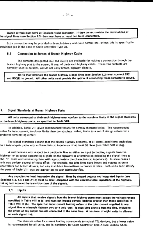
[image:24.881.84.772.257.577.2]Branch drivers must have at least one fixed connector. If they do not contain the terminations of the signal lines (see Section 7.3) they must have at least two fixed connectors.
Extra connectors may be provided on branch drivers and crate controllers, unless this is specifically prohibited (as in the case of Crate Controller Type A).
6.1
Connection to Screen of Branch Highway Cable
The contacts designated BSC and BSC(R) are available for making a connection through the branch highway port to the screen, if any, of the branch highway cable. These two contacts are normally used in parallel, and do not carry branch highway signals.
Units that terminate the branch highway signal lines (see Section 7.3) must connect BSC
and BSC(R) to ground. All other units must provide the option of connecting these contacts to ground.
7.
Signal Standards at Branch Highway Ports
All units connected to the branch highway must conform to the absolute limits of the signal standards
qt the branch highway ports, as specified in Table VIII.
In addition, Table VII I gives recommended values for certain characteristics. The recommended value for input current, to closer limits than the absolute value, leads to a set of design values for a preferred terminating circuit.
The signal standards assume that the branch :,ighway presents, at all ports, conditions equivalent to a twisted-pair cable with a characteristic impedance of at least 70 ohms (see Table VIII at (h•)).
A unit behaves with respect to a particular line as either an input (accepting signals from the highway) or an output (generating signals on the highway) or a termination (biassing the signal lines to the 'O' state and terminating them with approximately the characteristic impedance). In some cases a unit may perform several of these roles. For example, the BRW lines have inputs and outputs at crate controllers and branch drivers, and may also have terminations in branch drivers. Such units must satisfy the parts of Table VIII that are appropriate to each particular role.
Any capacitative load imposed on the signal lines by shaped outputs and integrated inputs (see Sections 4.3, 4.4.1 and A1.7) must be small compared with the characteristic impedance of the highway, taking into account the transition time of the signals.
7.1
Inputs
All inputs that receive signals from the branch highway ports must accept the voltage ranges
specified in Table VIII at (a) and must not impose current loadings greater than those specified in
Table VIII at (b). The specified input current loading refers to the total current supplied to any signal line at a branch highway port by a unit that is receiving signals from the line, including the effect of any output circuits connected to the same line. A maximum of eight units is allowed on each signal line.
[image:25.704.42.568.41.899.2]24
-TABLE VIII
Signal Standards at Branch Highway Ports
CONDITION LOGIC ABSOLUTE RECOMMENDED
at branch highway ports STATE LIMITS VALUES
INPUTS
a) Voltage range 0 +2.4V to +5.5V
accepted by unit 1 OV to + 1 . 2V ( 1 )
b) Maximum current 0 ±0.3mA
supplied by unit
1 +1.6mA ± 0.3mA* (2)
(see Section 7.1) ( ± 0.3mA for Crate
Controller Type A)
OUTPUTS
c) Voltage range 1 OV to +0.5V OV to +0.3V
generated by unit
d) Minimum current 1 127mA 133mA
sinking capabi I ity (3)
TERMINATION
e) Open circuit voltage 0 +4.5V max +4. 1 V preferred*
f) Short circuit current 1 50mA max
g) Terminating impedance 1000 preferred*
BRANCH HIGHWAY
h) Characteristic impedance 700 min 1000 max*
(1) Higher than
m
voltage levels provide an increased noise margin taking into account cable losses and reflections due to mismatches.(2) Low input currents result in smaller reflections. Receivers with high input impedance may feed current into the line
or draw
current from the line.(3) The current sinking capability is given by
Vo - Vout low+ S.I·
=
{127mA absolute minimumZ/2 '"low 133mA recommended minimum
where V0
=
4.5V maximum open circuit voltagevout low Jo.sv absolute
J
maximum low state output=
10.3V recommended voltage.Z = 70 Ohm minimum characteristic impedance lin low= 1.6mA maximum low state input current.
7.2
Outputs
Al I outputs that transmit signals through branch highway ports must be sources that allow wired-OR connections. In the '1' state the sources must produce signals within the voltage range specified in Table VIII at (c) and have the current sinking capability specified in Table VIII at (di, in order to drive eight inputs (see Section 7. 1) and two terminations
(see Section 7.3) under dynamic conditions. The 80, BTA and 8TB signals must be generated from sources that define the transition times (see Sections 4.3 and 4.4.1). The generation of other signals with defined transition times is permitted.
If the branch driver includes one termination for the highway, its current sinking capabi I ity at the appropriate lines of the port may be reduced accordingly.
7.3
Terminations
All 65 signal lines must be terminated at one end of the branch highway with a circuit
providing the appropriate 'pull-up' current to bias the line to the 'O' state, and the appropriate terminating impedance to limit signal reflections. All return lines and the connections to the cable screen must be connected to ground at this point. The current from each termination circuit into tne branch highway line in the logic '1' state must not exceed the short circuit current specified in Table VIII at (f).
It is strongly recommended that all 65 signal lines should be terminated at both ends of the branch highway.
It
is suggested that there should be a termination unit that can be used at either end of the highway by connecting it to the second branch highway port of the last crate controller or to the second port of the branch driver if this does not have internal terminations and is at the end of the branch.If such a termination unit is provided it must terminate all 65 signal I ines, and ground the return lines and connections to the cable saeen.
If all inputs connected to the branch highway impose the lower current loading recommended in Table VIII at (b), and the highway has a characteristic impedance between 70 and 100 ohms, the terminating circuits should be designed to have the target values for impedance and open circuit voltage given in Table VIII at (g) and (e) in order to achieve optimum speed and noise margin. If inputs have the higher absolute value for current loading it wi 11 be necessary to design the terminating circuits for the appropriate compromise between speed and noise margin to suit the particular application.
7.4
Off-line and Power-off Conditions
A crate controller must not generate '1' state outputs at its branch highway ports when in the off-line state and receiving normal power supplies.
26
-Appendix 1
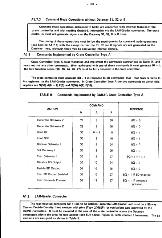
Specification of CAMAC Crate Controller Type A*
A 1.1
CAMAC Crate Controller Type A
In order to conform with the specification for CAMAC Crate Controller Type A, a crate controller must have all the mandatory features defined in this appendix. It must have no other features that would affect its interchangeability with any other Crate Controller Type A, taking into account the effect of such interchange on both hardware and software. It must be fully interchangeable with one conforming to Figure 7, although it need not have identical structure, internal signals (shown without the prefix 'B'
in Figure 7) or logical expressions.
A1 .2
Other Crate Controllers
It is recommended that other crate controllers should be interchangeable with Crate Controller Type A in respect of those features that they have in common, although they need not have al I the mandatory features of Crate Controller Type A and may have additional features.
A1.3
General Features
The crate controller must conform fully with the mandatory requirements of the CAMAC Specification, EUR 4100e, and the CAMAC Branch Highway Specification (Sections 1 - 7 of this document). It is
mandatory that all signal inputs at the branch highway ports of Crate Controller Type A must satisfy the lower input current standard(± 0.3mA) shown in Table VIII.
Crate Controller Type A must not occupy more than three stations. It should preferably be a double-width unit which engages with the Dataway at the control station and the adjacent normal station.
In addition to the two front panel connectors for branch highway ports (see Section A1 .4) the crate controller must have a rear-mounted connector for a link to an optional separate LAM-Grader unit (see Section A1.9).
A1.4
Front Panel
The crate controller must have all the following front panel features, and no other that would affect interchangeability (for exa111>le. the addition of indicators for test purposes is permitted).
a) There must be two connectors for branch highway ports, as defined in Section 6 of the branch highway specification. mounted with the correct orientation and with all corresponding contacts joined.
b) There must be a means of indicating the selected crate address (1 - 7). There must not be easy access at or tlwough the front panel to the means of changing the crate address.
c) There must be a means of selecting off~line status of the crate controller (see Section A1.10). d) There must be a coaxial connector for the Inhibit signal input. The type of connector and the
signal standard are specified in EUR 4100e, Sections 4.3.3 and 7.2.1, respectively.
e) There must be two push-buttons. or equivalent manual controls, for Initialise and Clear. These are only effective in the off-line state, and the front panel layout or markings should indicate this.
A1.5
Dataway Signals
A1.5.1
Data Signals
When the crate controller is on-line and addressed during a read command operation with a station number other than N(30) it must retransmit the signals from the 24 Dataway Read lines through intrinsic OR outputs to the BRW I ines. Crate Controller Type A must have gates between the Rand BRW lines so that this transfer of read data occurs only when the crate controller is addressed and on-line, for example when BCR .. (BTA + BTB.) = 1. During write operations with
I I
station number other than (N30) it must retransmit the signals from the 24 BRW lines to the Dataway Write I ines.
It is recommended that all crate controllers should include gates between the Rand BRW lines, and between the BRW and W lines, so that these transfers of data are only effective when the crate controller is addressed and on-I ine. These gates may further I imit the transfers to read operations (BF16.BF8 = 1) and write operations (BF16.BF8 = 1), respectively. However, the crate controller is permitted to generate signals on the Dataway Write I ines during any operation, but other units connected to the Dataway can only rely on the presence of such signals during Dataway write operations.
A1.5.2
Command Signals
The branch highway command signals BN, BA and BF should be conditioned in the crate controller, for example, by integration or by staticising at a time related to BTA O __. 1, in order to protect the Dataway command lines from the effects of cross-talk into branch highway command lines.
The sub-address and function signals from the BA and BF I ines must be re-transmitted by the crate controller on the Dataway A and F I ines during all command mode operations when the controller is on-line and addressed.
In a double-width crate controller each of the Station Number codes N(1) through to N(23) must be decoded in the crate controller to produce a signal on the corresponding Dataway line N1 to N23.
Command operations with N(26) must generate Dataway signals on all the lines N1 through to N23, Command operations with N(24) generate Dataway signals on N1 through to N23 as determined by the contents of a 23-bit Station Number Register (SNR). This register is loaded from BRW1-BRW23 by the conmand N(30).A(8).F(16). The bit of the Station Number Register that is loaded from BRW1 controls the state of N1, etc. The register is not reset by the Dataway
Initialise signal (Z).
A triple-width controller may alternatively have a 22-bit SNR. decode N( 1) through to N(22), and generate signals on Dataway lines N1 to N22.
A 1.5.3
Common Control Signals
The Dataway Initialise signal (Z) must be generated in response to the command
N(28).A(8).F(26) and to the Branch Initialise signal (see Section 4.5.1). It must also be generated in response to the manual Initialise control, but only when the crate controller is in the off-line state.
The Dataway Clear signal (C) must be generated in response to the command N(28).A(9).F(26). It must also be generated in response to the manual Clear control, but only when the crate
controller is in the off•line state.
28
-The Dataway Inhibit signal (I) must be initiated when an on-line crate controller generates Dataway Initialise (Z), and must reach a maintained '1' state not later than time t
3 (See EUR 4100e, figure 9). When some other unit generates Initialise (accompanied by Inhibit) an on-line crate controller must generate Inhibit in response to Dataway Z gated by S2. The Inhibit signal must also be generated in response to the command N(30).A(9).F(26). In all these cases the Inhibit signal must be maintained by the crate controller until reset by the command (N30).A(9).F(24).
It
must also be generated while the front panel Inhibit signal is present.The conmand N(30).A(9).F(27) must produce a O
=
1 response if there is a '1' state signal on the Dataway Inhibit line.A 1.5.4
Patch Connections
Crate Controller Type A must not use the patch pins of the Dataway stations that it occupies.
A1.6
Demand Handling
A1.6.1
Branch Demand
The Branch Demand signal (BD) must be derived, subject to the following conditions, from the OR combination of an external demand signal from contact 48 of the LAM-Grader connector and an internal demand signal which is the OR of the 24 GL signals received via the LAM-Grader connector.
The output of the branch demand signal to the BD line must be disabled by the command N(30).A(10).F(24) or by the Dataway Initialise signal (Z) with S2. It must be enabled by the command N(30).A(10).F(26). The command N(30).A(10).F(27) must give a BO= 1 response if the output of BD is enabled. The command N(30) •. A(11).F(27) must give a BO= 1 response if the OR of the internal and external demands is in the '1' state, even if the output of BD is disabled.
The internal demand signal must be inhibited by the '1' state of the Inhibit Internal D signal from contact 51 of the LAM-Grader connector.
A1.6.2
Graded-l
In response to a Graded-L Request signal (BG= 1), accompanied by BCRi = 1, the crate controller must generate the Graded-L Operation signal on contact 1 of the LAM-Grader connector. It must accept the Graded-L signals GL 1-GL24 from the LAM-Grader connector and transmit them to the BRW I ines (GL 1 to BRW1, etc.).
The crate controller must also accept the Graded-L signals from the LAM-Grader connector and transmit them to the BRW lines in response to command mode operations with
N(30).A(0-7).F(O). (See Section A1.9.4).
In both cases the GL information must be transferred from the LAM-Grader connector to the BRW lines with minimum delay, and the signals must not appear on the Dataway Read lines.